Debug
The debug system offers a flexible and powerful mechanism for non-intrusive debugging.
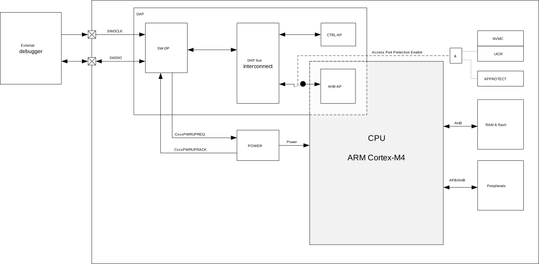
- Two-pin serial wire debug (SWD) interface
- Flash patch and breakpoint (FPB) unit that supports the following comparators:
- Two literal comparators
- Six instruction comparators
DAP - Debug access port
An external debugger can access the device via the DAP.
The debug access port (DAP) implements a standard ARM® CoreSight™ serial wire debug port (SW-DP), which implements the serial wire debug protocol (SWD). SWD is a two-pin serial interface, see SWDCLK and SWDIO in Debug overview.
In addition to the default access port in CPU (AHB-AP), the DAP includes a custom control access port (CTRL-AP). The CTRL-AP is described in more detail in CTRL-AP - Control access port.
- The SWDIO line has an internal pull-up resistor.
- The SWDCLK line has an internal pull-down resistor.
Access port protection
Access port protection blocks the debugger from read and write access to all CPU registers and memory-mapped addresses when enabled.
Access port protection is enabled and disabled differently depending on the build code of the device.
Access port protection controlled by hardware
This information refers to build codes Dxx and earlier.
By default, access port protection is disabled.
Access port protection is enabled by writing UICR.APPROTECT to Enabled and performing
any reset. See Reset for more information.
Access port protection is disabled by issuing an ERASEALL command via CTRL-AP. This command will erase the flash,
UICR, and RAM, including UICR.APPROTECT. Erasing UICR will
set UICR.APPROTECT value to Disabled. CTRL-AP is described in more detail in CTRL-AP - Control access port.
Access port protection controlled by hardware and software
This information refers to build codes Exx and later.
By default, access port protection is enabled.
Access port protection is disabled by issuing an ERASEALL command via CTRL-AP. Read CTRL-AP.APPROTECTSTATUS to ensure that access port protection is disabled, and repeat the ERASEALL command if needed. This command will erase the flash, UICR, and RAM. CTRL-AP is described in more detail in CTRL-AP - Control access port. Access port protection will remain disabled until one of the following occurs:
- Pin reset
- Power or brownout reset
- Watchdog reset if not in Debug Interface Mode, see Debug Interface mode
- Wake from System OFF if not in Emulated System OFF
To keep access port protection disabled, the following actions must be performed:
- Program UICR.APPROTECT to
HwDisabled. This disables the hardware part of the access port protection scheme after the first reset of any type. The hardware part of the access port protection will stay disabled as long as UICR.APPROTECT is not overwritten. - Firmware must write APPROTECT.DISABLE to
SwDisable. This disables the software part of the access port protection scheme.
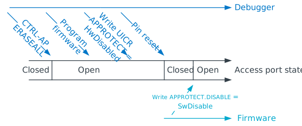
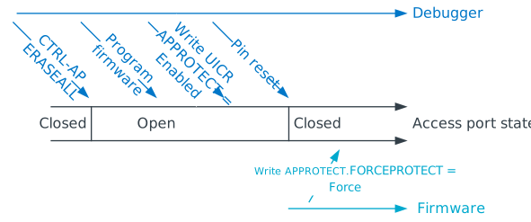
Access port protection is enabled when the disabling conditions are not present. For
additional security, it is recommended to write Enabled to UICR.APPROTECT, and have firmware write
Force to APPROTECT.FORCEPROTECT. This is illustrated in the following figure.
Registers
| Base address | Peripheral | Instance | Description | Configuration | |
|---|---|---|---|---|---|
| 0x40000000 | APPROTECT | APPROTECT | APPROTECT control | ||
| Register | Offset | Description | |
|---|---|---|---|
| FORCEPROTECT | 0x550 | Software force enable APPROTECT mechanism until next reset. | |
| DISABLE | 0x558 | Software disable APPROTECT mechanism | |
FORCEPROTECT
Address offset: 0x550
Software force enable APPROTECT mechanism until next reset.
| Bit number | 31 | 30 | 29 | 28 | 27 | 26 | 25 | 24 | 23 | 22 | 21 | 20 | 19 | 18 | 17 | 16 | 15 | 14 | 13 | 12 | 11 | 10 | 9 | 8 | 7 | 6 | 5 | 4 | 3 | 2 | 1 | 0 | |||
|---|---|---|---|---|---|---|---|---|---|---|---|---|---|---|---|---|---|---|---|---|---|---|---|---|---|---|---|---|---|---|---|---|---|---|---|
| ID | A | A | A | A | A | A | A | A | |||||||||||||||||||||||||||
| Reset 0xFFFFFFFF | 1 | 1 | 1 | 1 | 1 | 1 | 1 | 1 | 1 | 1 | 1 | 1 | 1 | 1 | 1 | 1 | 1 | 1 | 1 | 1 | 1 | 1 | 1 | 1 | 1 | 1 | 1 | 1 | 1 | 1 | 1 | 1 | |||
| ID | Access | Field | Value ID | Value | Description | ||||||||||||||||||||||||||||||
| A | RW1 | FORCEPROTECT | Write 0x0 to force enable APPROTECT mechanism | ||||||||||||||||||||||||||||||||
Force | 0x0 | Software force enable APPROTECT mechanism | |||||||||||||||||||||||||||||||||
DISABLE
Address offset: 0x558
Software disable APPROTECT mechanism
| Bit number | 31 | 30 | 29 | 28 | 27 | 26 | 25 | 24 | 23 | 22 | 21 | 20 | 19 | 18 | 17 | 16 | 15 | 14 | 13 | 12 | 11 | 10 | 9 | 8 | 7 | 6 | 5 | 4 | 3 | 2 | 1 | 0 | |||
|---|---|---|---|---|---|---|---|---|---|---|---|---|---|---|---|---|---|---|---|---|---|---|---|---|---|---|---|---|---|---|---|---|---|---|---|
| ID | A | A | A | A | A | A | A | A | |||||||||||||||||||||||||||
| Reset 0x00000000 | 0 | 0 | 0 | 0 | 0 | 0 | 0 | 0 | 0 | 0 | 0 | 0 | 0 | 0 | 0 | 0 | 0 | 0 | 0 | 0 | 0 | 0 | 0 | 0 | 0 | 0 | 0 | 0 | 0 | 0 | 0 | 0 | |||
| ID | Access | Field | Value ID | Value | Description | ||||||||||||||||||||||||||||||
| A | RW | DISABLE | Software disable APPROTECT mechanism | ||||||||||||||||||||||||||||||||
SwDisable | 0x5A | Software disable APPROTECT mechanism | |||||||||||||||||||||||||||||||||
CTRL-AP - Control access port
The control access port (CTRL-AP) is a custom access port that enables control of the device when other access ports in the DAP are disabled by the access port protection.
Access port protection is described in more detail in Access port protection.
Control access port has the following features:
- Soft reset - see Reset for more information
- Disabling of access port protection - device control is allowed through CTRL-AP even when all other access ports in DAP are disabled by access port protection
Registers
| Register | Offset | Description | |
|---|---|---|---|
| RESET | 0x000 | Soft reset triggered through CTRL-AP | |
| ERASEALL | 0x004 | Erase all | |
| ERASEALLSTATUS | 0x008 | Status register for the ERASEALL operation | |
| APPROTECTSTATUS | 0x00C | Status register for access port protection | |
| IDR | 0x0FC | CTRL-AP identification register, IDR | |
RESET
Address offset: 0x000
Soft reset triggered through CTRL-AP
| Bit number | 31 | 30 | 29 | 28 | 27 | 26 | 25 | 24 | 23 | 22 | 21 | 20 | 19 | 18 | 17 | 16 | 15 | 14 | 13 | 12 | 11 | 10 | 9 | 8 | 7 | 6 | 5 | 4 | 3 | 2 | 1 | 0 | |||
|---|---|---|---|---|---|---|---|---|---|---|---|---|---|---|---|---|---|---|---|---|---|---|---|---|---|---|---|---|---|---|---|---|---|---|---|
| ID | A | ||||||||||||||||||||||||||||||||||
| Reset 0x00000000 | 0 | 0 | 0 | 0 | 0 | 0 | 0 | 0 | 0 | 0 | 0 | 0 | 0 | 0 | 0 | 0 | 0 | 0 | 0 | 0 | 0 | 0 | 0 | 0 | 0 | 0 | 0 | 0 | 0 | 0 | 0 | 0 | |||
| ID | Access | Field | Value ID | Value | Description | ||||||||||||||||||||||||||||||
| A | RW | RESET | Soft reset triggered through CTRL-AP. See Reset behavior in POWER chapter for more details. | ||||||||||||||||||||||||||||||||
NoReset | 0 | Reset is not active | |||||||||||||||||||||||||||||||||
Reset | 1 | Reset is active. Device is held in reset. | |||||||||||||||||||||||||||||||||
ERASEALL
Address offset: 0x004
Erase all
| Bit number | 31 | 30 | 29 | 28 | 27 | 26 | 25 | 24 | 23 | 22 | 21 | 20 | 19 | 18 | 17 | 16 | 15 | 14 | 13 | 12 | 11 | 10 | 9 | 8 | 7 | 6 | 5 | 4 | 3 | 2 | 1 | 0 | |||
|---|---|---|---|---|---|---|---|---|---|---|---|---|---|---|---|---|---|---|---|---|---|---|---|---|---|---|---|---|---|---|---|---|---|---|---|
| ID | A | ||||||||||||||||||||||||||||||||||
| Reset 0x00000000 | 0 | 0 | 0 | 0 | 0 | 0 | 0 | 0 | 0 | 0 | 0 | 0 | 0 | 0 | 0 | 0 | 0 | 0 | 0 | 0 | 0 | 0 | 0 | 0 | 0 | 0 | 0 | 0 | 0 | 0 | 0 | 0 | |||
| ID | Access | Field | Value ID | Value | Description | ||||||||||||||||||||||||||||||
| A | W | ERASEALL | Erase all flash and RAM | ||||||||||||||||||||||||||||||||
NoOperation | 0 | No operation | |||||||||||||||||||||||||||||||||
Erase | 1 | Erase all flash and RAM | |||||||||||||||||||||||||||||||||
ERASEALLSTATUS
Address offset: 0x008
Status register for the ERASEALL operation
| Bit number | 31 | 30 | 29 | 28 | 27 | 26 | 25 | 24 | 23 | 22 | 21 | 20 | 19 | 18 | 17 | 16 | 15 | 14 | 13 | 12 | 11 | 10 | 9 | 8 | 7 | 6 | 5 | 4 | 3 | 2 | 1 | 0 | |||
|---|---|---|---|---|---|---|---|---|---|---|---|---|---|---|---|---|---|---|---|---|---|---|---|---|---|---|---|---|---|---|---|---|---|---|---|
| ID | A | ||||||||||||||||||||||||||||||||||
| Reset 0x00000000 | 0 | 0 | 0 | 0 | 0 | 0 | 0 | 0 | 0 | 0 | 0 | 0 | 0 | 0 | 0 | 0 | 0 | 0 | 0 | 0 | 0 | 0 | 0 | 0 | 0 | 0 | 0 | 0 | 0 | 0 | 0 | 0 | |||
| ID | Access | Field | Value ID | Value | Description | ||||||||||||||||||||||||||||||
| A | R | ERASEALLSTATUS | Status register for the ERASEALL operation | ||||||||||||||||||||||||||||||||
Ready | 0 | ERASEALL is ready | |||||||||||||||||||||||||||||||||
Busy | 1 | ERASEALL is busy (on-going) | |||||||||||||||||||||||||||||||||
APPROTECTSTATUS
Address offset: 0x00C
Status register for access port protection
| Bit number | 31 | 30 | 29 | 28 | 27 | 26 | 25 | 24 | 23 | 22 | 21 | 20 | 19 | 18 | 17 | 16 | 15 | 14 | 13 | 12 | 11 | 10 | 9 | 8 | 7 | 6 | 5 | 4 | 3 | 2 | 1 | 0 | |||
|---|---|---|---|---|---|---|---|---|---|---|---|---|---|---|---|---|---|---|---|---|---|---|---|---|---|---|---|---|---|---|---|---|---|---|---|
| ID | A | ||||||||||||||||||||||||||||||||||
| Reset 0x00000000 | 0 | 0 | 0 | 0 | 0 | 0 | 0 | 0 | 0 | 0 | 0 | 0 | 0 | 0 | 0 | 0 | 0 | 0 | 0 | 0 | 0 | 0 | 0 | 0 | 0 | 0 | 0 | 0 | 0 | 0 | 0 | 0 | |||
| ID | Access | Field | Value ID | Value | Description | ||||||||||||||||||||||||||||||
| A | R | APPROTECTSTATUS | Status register for access port protection | ||||||||||||||||||||||||||||||||
Enabled | 0 | Access port protection enabled | |||||||||||||||||||||||||||||||||
Disabled | 1 | Access port protection not enabled | |||||||||||||||||||||||||||||||||
IDR
Address offset: 0x0FC
CTRL-AP identification register, IDR
| Bit number | 31 | 30 | 29 | 28 | 27 | 26 | 25 | 24 | 23 | 22 | 21 | 20 | 19 | 18 | 17 | 16 | 15 | 14 | 13 | 12 | 11 | 10 | 9 | 8 | 7 | 6 | 5 | 4 | 3 | 2 | 1 | 0 | |||
|---|---|---|---|---|---|---|---|---|---|---|---|---|---|---|---|---|---|---|---|---|---|---|---|---|---|---|---|---|---|---|---|---|---|---|---|
| ID | E | E | E | E | D | D | D | D | C | C | C | C | C | C | C | B | B | B | B | A | A | A | A | A | A | A | A | ||||||||
| Reset 0x02880000 | 0 | 0 | 0 | 0 | 0 | 0 | 1 | 0 | 1 | 0 | 0 | 0 | 1 | 0 | 0 | 0 | 0 | 0 | 0 | 0 | 0 | 0 | 0 | 0 | 0 | 0 | 0 | 0 | 0 | 0 | 0 | 0 | |||
| ID | Access | Field | Value ID | Value | Description | ||||||||||||||||||||||||||||||
| A | R | APID | AP identification | ||||||||||||||||||||||||||||||||
| B | R | CLASS | Access port (AP) class | ||||||||||||||||||||||||||||||||
NotDefined | 0x0 | No defined class | |||||||||||||||||||||||||||||||||
MEMAP | 0x8 | Memory access port | |||||||||||||||||||||||||||||||||
| C | R | JEP106ID | JEDEC JEP106 identity code | ||||||||||||||||||||||||||||||||
| D | R | JEP106CONT | JEDEC JEP106 continuation code | ||||||||||||||||||||||||||||||||
| E | R | REVISION | Revision | ||||||||||||||||||||||||||||||||
Electrical specification
Control access port
| Symbol | Description | Min. | Typ. | Max. | Units | ||||
|---|---|---|---|---|---|---|---|---|---|
| Rpull | Internal SWDIO and SWDCLK pull up/down resistance | 13 | kΩ | ||||||
| fSWDCLK | SWDCLK frequency | 0.125 | 8 | MHz |
Debug Interface mode
Before an external debugger can access either CPU's access port (AHB-AP) or the control access port (CTRL-AP), the debugger must first request the device to power up via CxxxPWRUPREQ in the SWJ-DP.
If the device is in System OFF when power is requested via CxxxPWRUPREQ, the system will wake up and the DIF flag in RESETREAS will be set. The device is in the Debug Interface mode as long as the debugger is requesting power via CxxxPWRUPREQ. Once the debugger stops requesting power via CxxxPWRUPREQ, the device is back in normal mode. Some peripherals behave differently in Debug Interface mode compared to normal mode. These differences are described in more detail in the chapters of the peripherals that are affected.
When a debug session is over, the external debugger must make sure to put the device back into normal mode since the overall power consumption is higher in Debug Interface mode than in normal mode.
For details on how to use the debug capabilities, read the debug documentation of your IDE.
Real-time debug
The nRF52810 supports real-time debugging.
Real-time debugging allows interrupts to execute to completion in real time when breakpoints are set in Thread mode or lower priority interrupts. This enables developers to set breakpoints and single-step through the code without the risk of real-time event-driven threads running at higher priority failing. For example, this enables the device to continue to service the high-priority interrupts of an external controller or sensor without failure or loss of state synchronization while the developer steps through code in a low-priority thread.