TIMER — Timer/counter
The TIMER can operate in two modes: timer and counter.
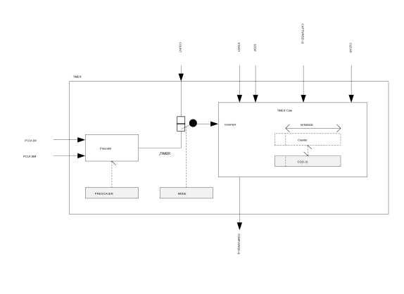
The timer/counter runs on the high-frequency clock source (HFCLK) and includes a four-bit (1/2X) prescaler that can divide the timer input clock from the HFCLK controller. Clock source selection between PCLK16M and PCLK1M is automatic according to TIMER base frequency set by the prescaler. The TIMER base frequency is always given as 16 MHz divided by the prescaler value.
The PPI system allows a TIMER event to trigger a task of any other system peripheral of the device. The PPI system also enables the TIMER task/event features to generate periodic output and PWM signals to any GPIO. The number of input/outputs used at the same time is limited by the number of GPIOTE channels.
The TIMER can operate in two modes, Timer mode and Counter mode. In both modes, the TIMER is started by triggering the START task, and stopped by triggering the STOP task. After the timer is stopped the timer can resume timing/counting by triggering the START task again. When timing/counting is resumed, the timer will continue from the value it had prior to being stopped.
In Timer mode, the TIMER's internal Counter register is incremented by one for every tick of the timer frequency fTIMER as illustrated in Block schematic for timer/counter. The timer frequency is derived from PCLK16M as shown below, using the values specified in the PRESCALER register:
fTIMER = 16 MHz / (2PRESCALER)
When fTIMER <= 1 MHz the TIMER will use PCLK1M instead of PCLK16M for reduced power consumption.
In counter mode, the TIMER's internal Counter register is incremented by one each time the COUNT task is triggered, that is, the timer frequency and the prescaler are not utilized in counter mode. Similarly, the COUNT task has no effect in Timer mode.
The TIMER's maximum value is configured by changing the bit-width of the timer in the BITMODE register.
PRESCALER and the BITMODE must only be updated when the timer is stopped. If these registers are updated while the TIMER is started then this may result in unpredictable behavior.
When the timer is incremented beyond its maximum value the Counter register will overflow and the TIMER will automatically start over from zero.
The Counter register can be cleared, that is, its internal value set to zero explicitly, by triggering the CLEAR task.
The TIMER implements multiple capture/compare registers.
Independent of prescaler setting the accuracy of the TIMER is equivalent to one tick of the timer frequency fTIMER as illustrated in Block schematic for timer/counter.
Capture
The TIMER implements one capture task for every available capture/compare register.
Every time the CAPTURE[n] task is triggered, the Counter value is copied to the CC[n] register.
Compare
The TIMER implements one COMPARE event for every available capture/compare register.
A COMPARE event is generated when the Counter is incremented and then becomes equal to the value specified in one of the capture compare registers. When the Counter value becomes equal to the value specified in a capture compare register CC[n], the corresponding compare event COMPARE[n] is generated.
BITMODE specifies how many bits of the Counter register and the capture/compare register that are used when the comparison is performed. Other bits will be ignored.
Task delays
After the TIMER is started, the CLEAR task, COUNT task and the STOP task will guarantee to take effect within one clock cycle of the PCLK16M.
Task priority
If the START task and the STOP task are triggered at the same time, that is, within the same period of PCLK16M, the STOP task will be prioritized.
Registers
| Base address | Peripheral | Instance | Description | Configuration | |
|---|---|---|---|---|---|
| 0x40008000 | TIMER | TIMER0 | Timer 0 | This timer instance has 4 CC registers (CC[0..3]) | |
| 0x40009000 | TIMER | TIMER1 | Timer 1 | This timer instance has 4 CC registers (CC[0..3]) | |
| 0x4000A000 | TIMER | TIMER2 | Timer 2 | This timer instance has 4 CC registers (CC[0..3]) | |
| Register | Offset | Description | |
|---|---|---|---|
| TASKS_START | 0x000 | Start Timer | |
| TASKS_STOP | 0x004 | Stop Timer | |
| TASKS_COUNT | 0x008 | Increment Timer (Counter mode only) | |
| TASKS_CLEAR | 0x00C | Clear time | |
| TASKS_SHUTDOWN | 0x010 | Shut down timer | Deprecated |
| TASKS_CAPTURE[0] | 0x040 | Capture Timer value to CC[0] register | |
| TASKS_CAPTURE[1] | 0x044 | Capture Timer value to CC[1] register | |
| TASKS_CAPTURE[2] | 0x048 | Capture Timer value to CC[2] register | |
| TASKS_CAPTURE[3] | 0x04C | Capture Timer value to CC[3] register | |
| TASKS_CAPTURE[4] | 0x050 | Capture Timer value to CC[4] register | |
| TASKS_CAPTURE[5] | 0x054 | Capture Timer value to CC[5] register | |
| EVENTS_COMPARE[0] | 0x140 | Compare event on CC[0] match | |
| EVENTS_COMPARE[1] | 0x144 | Compare event on CC[1] match | |
| EVENTS_COMPARE[2] | 0x148 | Compare event on CC[2] match | |
| EVENTS_COMPARE[3] | 0x14C | Compare event on CC[3] match | |
| EVENTS_COMPARE[4] | 0x150 | Compare event on CC[4] match | |
| EVENTS_COMPARE[5] | 0x154 | Compare event on CC[5] match | |
| SHORTS | 0x200 | Shortcuts between local events and tasks | |
| INTENSET | 0x304 | Enable interrupt | |
| INTENCLR | 0x308 | Disable interrupt | |
| MODE | 0x504 | Timer mode selection | |
| BITMODE | 0x508 | Configure the number of bits used by the TIMER | |
| PRESCALER | 0x510 | Timer prescaler register | |
| CC[0] | 0x540 | Capture/Compare register 0 | |
| CC[1] | 0x544 | Capture/Compare register 1 | |
| CC[2] | 0x548 | Capture/Compare register 2 | |
| CC[3] | 0x54C | Capture/Compare register 3 | |
| CC[4] | 0x550 | Capture/Compare register 4 | |
| CC[5] | 0x554 | Capture/Compare register 5 | |
TASKS_START
Address offset: 0x000
Start Timer
| Bit number | 31 | 30 | 29 | 28 | 27 | 26 | 25 | 24 | 23 | 22 | 21 | 20 | 19 | 18 | 17 | 16 | 15 | 14 | 13 | 12 | 11 | 10 | 9 | 8 | 7 | 6 | 5 | 4 | 3 | 2 | 1 | 0 | |||
|---|---|---|---|---|---|---|---|---|---|---|---|---|---|---|---|---|---|---|---|---|---|---|---|---|---|---|---|---|---|---|---|---|---|---|---|
| ID | A | ||||||||||||||||||||||||||||||||||
| Reset 0x00000000 | 0 | 0 | 0 | 0 | 0 | 0 | 0 | 0 | 0 | 0 | 0 | 0 | 0 | 0 | 0 | 0 | 0 | 0 | 0 | 0 | 0 | 0 | 0 | 0 | 0 | 0 | 0 | 0 | 0 | 0 | 0 | 0 | |||
| ID | Access | Field | Value ID | Value | Description | ||||||||||||||||||||||||||||||
| A | W | TASKS_START | Start Timer | ||||||||||||||||||||||||||||||||
Trigger | 1 | Trigger task | |||||||||||||||||||||||||||||||||
TASKS_STOP
Address offset: 0x004
Stop Timer
| Bit number | 31 | 30 | 29 | 28 | 27 | 26 | 25 | 24 | 23 | 22 | 21 | 20 | 19 | 18 | 17 | 16 | 15 | 14 | 13 | 12 | 11 | 10 | 9 | 8 | 7 | 6 | 5 | 4 | 3 | 2 | 1 | 0 | |||
|---|---|---|---|---|---|---|---|---|---|---|---|---|---|---|---|---|---|---|---|---|---|---|---|---|---|---|---|---|---|---|---|---|---|---|---|
| ID | A | ||||||||||||||||||||||||||||||||||
| Reset 0x00000000 | 0 | 0 | 0 | 0 | 0 | 0 | 0 | 0 | 0 | 0 | 0 | 0 | 0 | 0 | 0 | 0 | 0 | 0 | 0 | 0 | 0 | 0 | 0 | 0 | 0 | 0 | 0 | 0 | 0 | 0 | 0 | 0 | |||
| ID | Access | Field | Value ID | Value | Description | ||||||||||||||||||||||||||||||
| A | W | TASKS_STOP | Stop Timer | ||||||||||||||||||||||||||||||||
Trigger | 1 | Trigger task | |||||||||||||||||||||||||||||||||
TASKS_COUNT
Address offset: 0x008
Increment Timer (Counter mode only)
| Bit number | 31 | 30 | 29 | 28 | 27 | 26 | 25 | 24 | 23 | 22 | 21 | 20 | 19 | 18 | 17 | 16 | 15 | 14 | 13 | 12 | 11 | 10 | 9 | 8 | 7 | 6 | 5 | 4 | 3 | 2 | 1 | 0 | |||
|---|---|---|---|---|---|---|---|---|---|---|---|---|---|---|---|---|---|---|---|---|---|---|---|---|---|---|---|---|---|---|---|---|---|---|---|
| ID | A | ||||||||||||||||||||||||||||||||||
| Reset 0x00000000 | 0 | 0 | 0 | 0 | 0 | 0 | 0 | 0 | 0 | 0 | 0 | 0 | 0 | 0 | 0 | 0 | 0 | 0 | 0 | 0 | 0 | 0 | 0 | 0 | 0 | 0 | 0 | 0 | 0 | 0 | 0 | 0 | |||
| ID | Access | Field | Value ID | Value | Description | ||||||||||||||||||||||||||||||
| A | W | TASKS_COUNT | Increment Timer (Counter mode only) | ||||||||||||||||||||||||||||||||
Trigger | 1 | Trigger task | |||||||||||||||||||||||||||||||||
TASKS_CLEAR
Address offset: 0x00C
Clear time
| Bit number | 31 | 30 | 29 | 28 | 27 | 26 | 25 | 24 | 23 | 22 | 21 | 20 | 19 | 18 | 17 | 16 | 15 | 14 | 13 | 12 | 11 | 10 | 9 | 8 | 7 | 6 | 5 | 4 | 3 | 2 | 1 | 0 | |||
|---|---|---|---|---|---|---|---|---|---|---|---|---|---|---|---|---|---|---|---|---|---|---|---|---|---|---|---|---|---|---|---|---|---|---|---|
| ID | A | ||||||||||||||||||||||||||||||||||
| Reset 0x00000000 | 0 | 0 | 0 | 0 | 0 | 0 | 0 | 0 | 0 | 0 | 0 | 0 | 0 | 0 | 0 | 0 | 0 | 0 | 0 | 0 | 0 | 0 | 0 | 0 | 0 | 0 | 0 | 0 | 0 | 0 | 0 | 0 | |||
| ID | Access | Field | Value ID | Value | Description | ||||||||||||||||||||||||||||||
| A | W | TASKS_CLEAR | Clear time | ||||||||||||||||||||||||||||||||
Trigger | 1 | Trigger task | |||||||||||||||||||||||||||||||||
TASKS_SHUTDOWN ( Deprecated )
Address offset: 0x010
Shut down timer
| Bit number | 31 | 30 | 29 | 28 | 27 | 26 | 25 | 24 | 23 | 22 | 21 | 20 | 19 | 18 | 17 | 16 | 15 | 14 | 13 | 12 | 11 | 10 | 9 | 8 | 7 | 6 | 5 | 4 | 3 | 2 | 1 | 0 | |||
|---|---|---|---|---|---|---|---|---|---|---|---|---|---|---|---|---|---|---|---|---|---|---|---|---|---|---|---|---|---|---|---|---|---|---|---|
| ID | A | ||||||||||||||||||||||||||||||||||
| Reset 0x00000000 | 0 | 0 | 0 | 0 | 0 | 0 | 0 | 0 | 0 | 0 | 0 | 0 | 0 | 0 | 0 | 0 | 0 | 0 | 0 | 0 | 0 | 0 | 0 | 0 | 0 | 0 | 0 | 0 | 0 | 0 | 0 | 0 | |||
| ID | Access | Field | Value ID | Value | Description | ||||||||||||||||||||||||||||||
| A | W | TASKS_SHUTDOWN | Shut down timer | Deprecated | |||||||||||||||||||||||||||||||
Trigger | 1 | Trigger task | |||||||||||||||||||||||||||||||||
TASKS_CAPTURE[n] (n=0..5)
Address offset: 0x040 + (n × 0x4)
Capture Timer value to CC[n] register
| Bit number | 31 | 30 | 29 | 28 | 27 | 26 | 25 | 24 | 23 | 22 | 21 | 20 | 19 | 18 | 17 | 16 | 15 | 14 | 13 | 12 | 11 | 10 | 9 | 8 | 7 | 6 | 5 | 4 | 3 | 2 | 1 | 0 | |||
|---|---|---|---|---|---|---|---|---|---|---|---|---|---|---|---|---|---|---|---|---|---|---|---|---|---|---|---|---|---|---|---|---|---|---|---|
| ID | A | ||||||||||||||||||||||||||||||||||
| Reset 0x00000000 | 0 | 0 | 0 | 0 | 0 | 0 | 0 | 0 | 0 | 0 | 0 | 0 | 0 | 0 | 0 | 0 | 0 | 0 | 0 | 0 | 0 | 0 | 0 | 0 | 0 | 0 | 0 | 0 | 0 | 0 | 0 | 0 | |||
| ID | Access | Field | Value ID | Value | Description | ||||||||||||||||||||||||||||||
| A | W | TASKS_CAPTURE | Capture Timer value to CC[n] register | ||||||||||||||||||||||||||||||||
Trigger | 1 | Trigger task | |||||||||||||||||||||||||||||||||
EVENTS_COMPARE[n] (n=0..5)
Address offset: 0x140 + (n × 0x4)
Compare event on CC[n] match
| Bit number | 31 | 30 | 29 | 28 | 27 | 26 | 25 | 24 | 23 | 22 | 21 | 20 | 19 | 18 | 17 | 16 | 15 | 14 | 13 | 12 | 11 | 10 | 9 | 8 | 7 | 6 | 5 | 4 | 3 | 2 | 1 | 0 | |||
|---|---|---|---|---|---|---|---|---|---|---|---|---|---|---|---|---|---|---|---|---|---|---|---|---|---|---|---|---|---|---|---|---|---|---|---|
| ID | A | ||||||||||||||||||||||||||||||||||
| Reset 0x00000000 | 0 | 0 | 0 | 0 | 0 | 0 | 0 | 0 | 0 | 0 | 0 | 0 | 0 | 0 | 0 | 0 | 0 | 0 | 0 | 0 | 0 | 0 | 0 | 0 | 0 | 0 | 0 | 0 | 0 | 0 | 0 | 0 | |||
| ID | Access | Field | Value ID | Value | Description | ||||||||||||||||||||||||||||||
| A | RW | EVENTS_COMPARE | Compare event on CC[n] match | ||||||||||||||||||||||||||||||||
NotGenerated | 0 | Event not generated | |||||||||||||||||||||||||||||||||
Generated | 1 | Event generated | |||||||||||||||||||||||||||||||||
SHORTS
Address offset: 0x200
Shortcuts between local events and tasks
| Bit number | 31 | 30 | 29 | 28 | 27 | 26 | 25 | 24 | 23 | 22 | 21 | 20 | 19 | 18 | 17 | 16 | 15 | 14 | 13 | 12 | 11 | 10 | 9 | 8 | 7 | 6 | 5 | 4 | 3 | 2 | 1 | 0 | |||
|---|---|---|---|---|---|---|---|---|---|---|---|---|---|---|---|---|---|---|---|---|---|---|---|---|---|---|---|---|---|---|---|---|---|---|---|
| ID | L | K | J | I | H | G | F | E | D | C | B | A | |||||||||||||||||||||||
| Reset 0x00000000 | 0 | 0 | 0 | 0 | 0 | 0 | 0 | 0 | 0 | 0 | 0 | 0 | 0 | 0 | 0 | 0 | 0 | 0 | 0 | 0 | 0 | 0 | 0 | 0 | 0 | 0 | 0 | 0 | 0 | 0 | 0 | 0 | |||
| ID | Access | Field | Value ID | Value | Description | ||||||||||||||||||||||||||||||
| A-F | RW | COMPARE[i]_CLEAR (i=0..5) | Shortcut between event COMPARE[i] and task CLEAR | ||||||||||||||||||||||||||||||||
Disabled | 0 | Disable shortcut | |||||||||||||||||||||||||||||||||
Enabled | 1 | Enable shortcut | |||||||||||||||||||||||||||||||||
| G-L | RW | COMPARE[i]_STOP (i=0..5) | Shortcut between event COMPARE[i] and task STOP | ||||||||||||||||||||||||||||||||
Disabled | 0 | Disable shortcut | |||||||||||||||||||||||||||||||||
Enabled | 1 | Enable shortcut | |||||||||||||||||||||||||||||||||
INTENSET
Address offset: 0x304
Enable interrupt
| Bit number | 31 | 30 | 29 | 28 | 27 | 26 | 25 | 24 | 23 | 22 | 21 | 20 | 19 | 18 | 17 | 16 | 15 | 14 | 13 | 12 | 11 | 10 | 9 | 8 | 7 | 6 | 5 | 4 | 3 | 2 | 1 | 0 | |||
|---|---|---|---|---|---|---|---|---|---|---|---|---|---|---|---|---|---|---|---|---|---|---|---|---|---|---|---|---|---|---|---|---|---|---|---|
| ID | F | E | D | C | B | A | |||||||||||||||||||||||||||||
| Reset 0x00000000 | 0 | 0 | 0 | 0 | 0 | 0 | 0 | 0 | 0 | 0 | 0 | 0 | 0 | 0 | 0 | 0 | 0 | 0 | 0 | 0 | 0 | 0 | 0 | 0 | 0 | 0 | 0 | 0 | 0 | 0 | 0 | 0 | |||
| ID | Access | Field | Value ID | Value | Description | ||||||||||||||||||||||||||||||
| A-F | RW | COMPARE[i] (i=0..5) | Write '1' to enable interrupt for event COMPARE[i] | ||||||||||||||||||||||||||||||||
Set | 1 | Enable | |||||||||||||||||||||||||||||||||
Disabled | 0 | Read: Disabled | |||||||||||||||||||||||||||||||||
Enabled | 1 | Read: Enabled | |||||||||||||||||||||||||||||||||
INTENCLR
Address offset: 0x308
Disable interrupt
| Bit number | 31 | 30 | 29 | 28 | 27 | 26 | 25 | 24 | 23 | 22 | 21 | 20 | 19 | 18 | 17 | 16 | 15 | 14 | 13 | 12 | 11 | 10 | 9 | 8 | 7 | 6 | 5 | 4 | 3 | 2 | 1 | 0 | |||
|---|---|---|---|---|---|---|---|---|---|---|---|---|---|---|---|---|---|---|---|---|---|---|---|---|---|---|---|---|---|---|---|---|---|---|---|
| ID | F | E | D | C | B | A | |||||||||||||||||||||||||||||
| Reset 0x00000000 | 0 | 0 | 0 | 0 | 0 | 0 | 0 | 0 | 0 | 0 | 0 | 0 | 0 | 0 | 0 | 0 | 0 | 0 | 0 | 0 | 0 | 0 | 0 | 0 | 0 | 0 | 0 | 0 | 0 | 0 | 0 | 0 | |||
| ID | Access | Field | Value ID | Value | Description | ||||||||||||||||||||||||||||||
| A-F | RW | COMPARE[i] (i=0..5) | Write '1' to disable interrupt for event COMPARE[i] | ||||||||||||||||||||||||||||||||
Clear | 1 | Disable | |||||||||||||||||||||||||||||||||
Disabled | 0 | Read: Disabled | |||||||||||||||||||||||||||||||||
Enabled | 1 | Read: Enabled | |||||||||||||||||||||||||||||||||
MODE
Address offset: 0x504
Timer mode selection
| Bit number | 31 | 30 | 29 | 28 | 27 | 26 | 25 | 24 | 23 | 22 | 21 | 20 | 19 | 18 | 17 | 16 | 15 | 14 | 13 | 12 | 11 | 10 | 9 | 8 | 7 | 6 | 5 | 4 | 3 | 2 | 1 | 0 | |||
|---|---|---|---|---|---|---|---|---|---|---|---|---|---|---|---|---|---|---|---|---|---|---|---|---|---|---|---|---|---|---|---|---|---|---|---|
| ID | A | A | |||||||||||||||||||||||||||||||||
| Reset 0x00000000 | 0 | 0 | 0 | 0 | 0 | 0 | 0 | 0 | 0 | 0 | 0 | 0 | 0 | 0 | 0 | 0 | 0 | 0 | 0 | 0 | 0 | 0 | 0 | 0 | 0 | 0 | 0 | 0 | 0 | 0 | 0 | 0 | |||
| ID | Access | Field | Value ID | Value | Description | ||||||||||||||||||||||||||||||
| A | RW | MODE | Timer mode | ||||||||||||||||||||||||||||||||
Timer | 0 | Select Timer mode | |||||||||||||||||||||||||||||||||
Counter | 1 | Select Counter mode | Deprecated | ||||||||||||||||||||||||||||||||
LowPowerCounter | 2 | Select Low Power Counter mode | |||||||||||||||||||||||||||||||||
BITMODE
Address offset: 0x508
Configure the number of bits used by the TIMER
| Bit number | 31 | 30 | 29 | 28 | 27 | 26 | 25 | 24 | 23 | 22 | 21 | 20 | 19 | 18 | 17 | 16 | 15 | 14 | 13 | 12 | 11 | 10 | 9 | 8 | 7 | 6 | 5 | 4 | 3 | 2 | 1 | 0 | |||
|---|---|---|---|---|---|---|---|---|---|---|---|---|---|---|---|---|---|---|---|---|---|---|---|---|---|---|---|---|---|---|---|---|---|---|---|
| ID | A | A | |||||||||||||||||||||||||||||||||
| Reset 0x00000000 | 0 | 0 | 0 | 0 | 0 | 0 | 0 | 0 | 0 | 0 | 0 | 0 | 0 | 0 | 0 | 0 | 0 | 0 | 0 | 0 | 0 | 0 | 0 | 0 | 0 | 0 | 0 | 0 | 0 | 0 | 0 | 0 | |||
| ID | Access | Field | Value ID | Value | Description | ||||||||||||||||||||||||||||||
| A | RW | BITMODE | Timer bit width | ||||||||||||||||||||||||||||||||
16Bit | 0 | 16 bit timer bit width | |||||||||||||||||||||||||||||||||
08Bit | 1 | 8 bit timer bit width | |||||||||||||||||||||||||||||||||
24Bit | 2 | 24 bit timer bit width | |||||||||||||||||||||||||||||||||
32Bit | 3 | 32 bit timer bit width | |||||||||||||||||||||||||||||||||
PRESCALER
Address offset: 0x510
Timer prescaler register
| Bit number | 31 | 30 | 29 | 28 | 27 | 26 | 25 | 24 | 23 | 22 | 21 | 20 | 19 | 18 | 17 | 16 | 15 | 14 | 13 | 12 | 11 | 10 | 9 | 8 | 7 | 6 | 5 | 4 | 3 | 2 | 1 | 0 | |||
|---|---|---|---|---|---|---|---|---|---|---|---|---|---|---|---|---|---|---|---|---|---|---|---|---|---|---|---|---|---|---|---|---|---|---|---|
| ID | A | A | A | A | |||||||||||||||||||||||||||||||
| Reset 0x00000004 | 0 | 0 | 0 | 0 | 0 | 0 | 0 | 0 | 0 | 0 | 0 | 0 | 0 | 0 | 0 | 0 | 0 | 0 | 0 | 0 | 0 | 0 | 0 | 0 | 0 | 0 | 0 | 0 | 0 | 1 | 0 | 0 | |||
| ID | Access | Field | Value ID | Value | Description | ||||||||||||||||||||||||||||||
| A | RW | PRESCALER | [0..9] | Prescaler value | |||||||||||||||||||||||||||||||
CC[n] (n=0..5)
Address offset: 0x540 + (n × 0x4)
Capture/Compare register n
| Bit number | 31 | 30 | 29 | 28 | 27 | 26 | 25 | 24 | 23 | 22 | 21 | 20 | 19 | 18 | 17 | 16 | 15 | 14 | 13 | 12 | 11 | 10 | 9 | 8 | 7 | 6 | 5 | 4 | 3 | 2 | 1 | 0 | |||
|---|---|---|---|---|---|---|---|---|---|---|---|---|---|---|---|---|---|---|---|---|---|---|---|---|---|---|---|---|---|---|---|---|---|---|---|
| ID | A | A | A | A | A | A | A | A | A | A | A | A | A | A | A | A | A | A | A | A | A | A | A | A | A | A | A | A | A | A | A | A | |||
| Reset 0x00000000 | 0 | 0 | 0 | 0 | 0 | 0 | 0 | 0 | 0 | 0 | 0 | 0 | 0 | 0 | 0 | 0 | 0 | 0 | 0 | 0 | 0 | 0 | 0 | 0 | 0 | 0 | 0 | 0 | 0 | 0 | 0 | 0 | |||
| ID | Access | Field | Value ID | Value | Description | ||||||||||||||||||||||||||||||
| A | RW | CC | Capture/Compare value Only the number of bits indicated by BITMODE will be used by the TIMER. | ||||||||||||||||||||||||||||||||