Power and clock management
Power and clock management in nRF52832 is optimized for ultra-low power applications.
The core of the power and clock management system is the Power Management Unit (PMU) illustrated in Figure 1.
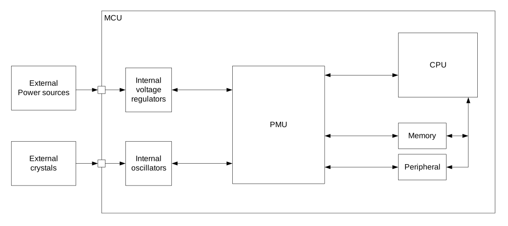
The user application is not required to actively control power and clock, since the PMU is able to automatically detect which resources are required by the different components in the system at any given time. The PMU will continuously optimize the system based on this information to achieve the lowest power consumption possible without user interaction.
Current consumption scenarios
As the system is being constantly tuned by the PMU, estimating the energy consumption of an application can be challenging if the designer is not able to do measurements on the hardware directly. See Electrical specification for application scenarios showing average current drawn from the VDD supply.
Each scenario specifies a set of active operations and conditions applying to the given scenario. Table 1 shows the conditions used for a scenario unless otherwise is stated in the scenario description.
| Condition | Value |
|---|---|
| VDD | 3 V |
| Temperature | 25°C |
| CPU | WFI/WFE sleep |
| Peripherals | All idle |
| Clock | Not running |
| Regulator | DCDC |
Electrical specification
Current consumption: Radio
| Symbol | Description | Min. | Typ. | Max. | Units | ||||
|---|---|---|---|---|---|---|---|---|---|
| IRADIO_TX0 | 0 dBm TX @ 1 Mb/s Bluetooth Low Energy mode, Clock = HFXO | 7.1 | mA | ||||||
| IRADIO_TX1 | -40 dBm TX @ 1 Mb/s Bluetooth Low Energy mode, Clock = HFXO | 4.1 | mA | ||||||
| IRADIO_RX0 | Radio RX @ 1 Mb/s Bluetooth Low Energy mode, Clock = HFXO | 6.5 | mA |
Current consumption: Radio protocol configurations
| Symbol | Description | Min. | Typ. | Max. | Units | ||||
|---|---|---|---|---|---|---|---|---|---|
| IS0 | CPU running CoreMark from Flash, Radio 0 dBm TX @ 1 Mb/s Bluetooth Low Energy mode, Clock = HFXO, Cache enabled | 9.2 | mA | ||||||
| IS1 | CPU running CoreMark from Flash, Radio RX @ 1 Mb/s Bluetooth Low Energy mode, Clock = HFXO, Cache enabled | 9.2 | mA |
Current consumption: Ultra-low power
| Symbol | Description | Min. | Typ. | Max. | Units | ||||
|---|---|---|---|---|---|---|---|---|---|
| ION_RAMOFF_EVENT | System ON, No RAM retention, Wake on any event | 1.2 | µA | ||||||
| ION_RAMON_EVENT | System ON, Full RAM retention, Wake on any event | 1.5 | µA | ||||||
| ION_RAMOFF_RTC | System ON, No RAM retention, Wake on RTC | 1.9 | µA | ||||||
| IOFF_RAMOFF_RESET | System OFF, No RAM retention, Wake on reset | 0.3 | µA | ||||||
| IOFF_RAMOFF_GPIO | System OFF, No RAM retention, Wake on GPIO | 0.3 | µA | ||||||
| IOFF_RAMOFF_LPCOMP | System OFF, No RAM retention, Wake on LPCOMP | 1.9 | µA | ||||||
| IOFF_RAMOFF_NFC | System OFF, No RAM retention, Wake on NFC field | 0.7 | µA | ||||||
| IOFF_RAMON_RESET | System OFF, Full 64 kB RAM retention, Wake on reset | 0.7 | µA |