RTC — Real-time counter
The Real-time counter (RTC) module provides a generic, low power timer on the low-frequency clock source (LFCLK).
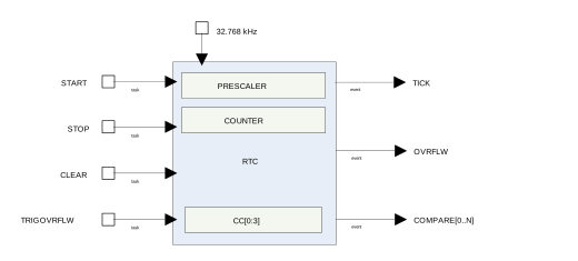
The RTC module features a 24-bit COUNTER, a 12-bit (1/X) prescaler, capture/compare registers, and a tick event generator for low power, tickless RTOS implementation.
Clock source
The RTC will run off the LFCLK.
The COUNTER resolution will therefore be 30.517 μs. Depending on the source, the RTC is able to run while the HFCLK is OFF and PCLK16M is not available.
The software has to explicitely start LFCLK before using the RTC.
See CLOCK — Clock control for more information about clock sources.
Resolution versus overflow and the PRESCALER
Counter increment frequency:
fRTC [kHz] = 32.768 / (PRESCALER + 1 )
The PRESCALER register is read/write when the RTC is stopped. The PRESCALER register is read-only once the RTC is STARTed. Writing to the PRESCALER register when the RTC is started has no effect.
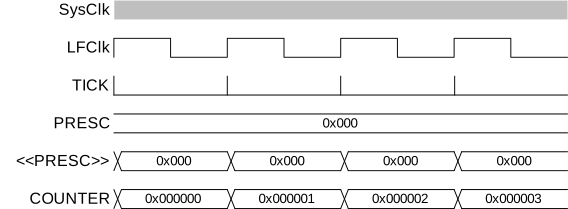
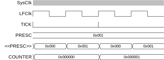
The PRESCALER is restarted on START, CLEAR and TRIGOVRFLW, that is, the prescaler value is latched to an internal register (<<PRESC>>) on these tasks.
Examples:
Desired COUNTER frequency 100 Hz (10 ms counter period)
PRESCALER = round(32.768 kHz / 100 Hz) - 1 = 327
fRTC = 99.9 Hz
10009.576 μs counter period
Desired COUNTER frequency 8 Hz (125 ms counter period)
PRESCALER = round(32.768 kHz / 8 Hz) – 1 = 4095
fRTC = 8 Hz
125 ms counter period
| Prescaler | Counter resolution | Overflow |
|---|---|---|
| 0 | 30.517 μs | 512 seconds |
| 28-1 | 7812.5 μs | 131072 seconds |
| 212-1 | 125 ms | 582.542 hours |
COUNTER register
The COUNTER increments on LFCLK when the internal PRESCALER register (<<PRESC>>) is 0x00. <<PRESC>> is reloaded from the PRESCALER register. If enabled, the TICK event occurs on each increment of the COUNTER. The TICK event is disabled by default.
Overflow features
The TRIGOVRFLW task sets the COUNTER value to 0xFFFFF0 to allow SW test of the overflow condition.
OVRFLW occurs when COUNTER overflows from 0xFFFFFF to 0.
TICK event
The TICK event enables low power "tick-less" RTOS implementation as it optionally provides a regular interrupt source for a RTOS without the need to use the ARM® SysTick feature.
Using the RTC TICK event rather than the SysTick allows the CPU to be powered down while still keeping RTOS scheduling active.
Event control feature
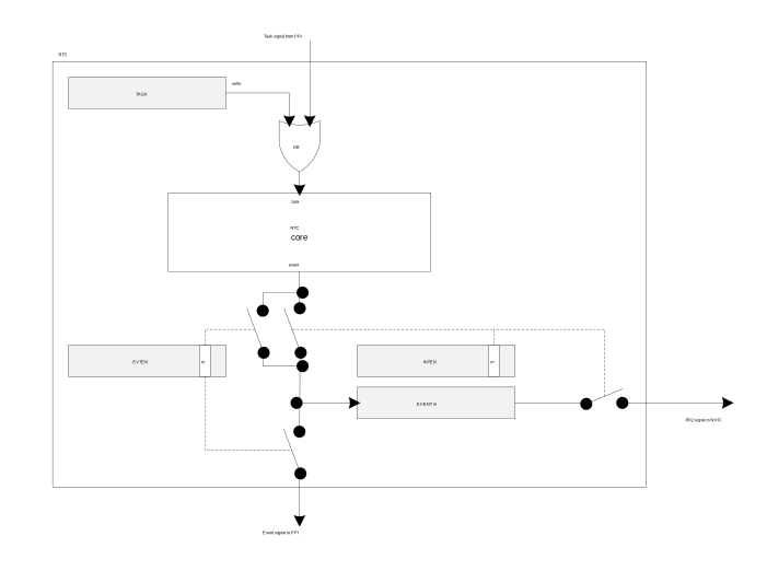
To optimize RTC power consumption, events in the RTC can be individually disabled to prevent PCLK16M and HFCLK being requested when those events are triggered. This is managed using the EVTEN register.
For example, if the TICK event is not required for an application, this event should be disabled as it is frequently occurring and may increase power consumption if HFCLK otherwise could be powered down for long durations.
This means that the RTC implements a slightly different task and event system compared to the standard system described in Peripheral interface. The RTC task and event system is illustrated in Figure 4.
Compare feature
There are a number of Compare registers.
For more information, see Registers.
When setting a compare register, the following behavior of the RTC compare event should be noted:
- If a CC register value is 0 when a CLEAR task is set, this will not trigger a COMPARE event.
Figure 5. Timing diagram - COMPARE_CLEAR 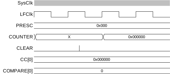
- If a CC register is N and the COUNTER value is N when the START task is set, this will not
trigger a COMPARE event.
Figure 6. Timing diagram - COMPARE_START 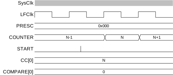
- COMPARE occurs when a CC register is N and the COUNTER value transitions from N-1 to N.
Figure 7. Timing diagram - COMPARE 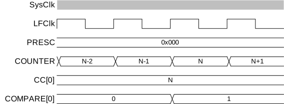
- If the COUNTER is N, writing N+2 to a CC register is guaranteed to trigger a COMPARE event
at N+2.
Figure 8. Timing diagram - COMPARE_N+2 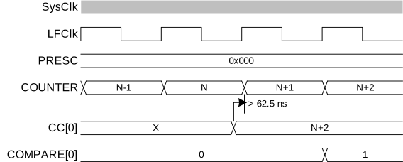
- If the COUNTER is N, writing N or N+1 to a CC register may not trigger a COMPARE event.
Figure 9. Timing diagram - COMPARE_N+1 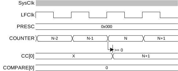
If the COUNTER is N and the current CC register value is N+1 or N+2 when a new CC value is written, a match may trigger on the previous CC value before the new value takes effect. If the current CC value greater than N+2 when the new value is written, there will be no event due to the old value.
Figure 10. Timing diagram - COMPARE_N-1 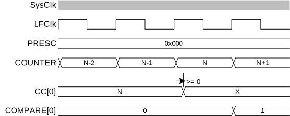
TASK and EVENT jitter/delay
Jitter or delay in the RTC is due to the peripheral clock being a low frequency clock (LFCLK) which is not synchronous to the faster PCLK16M.
Registers in the peripheral interface, part of the PCLK16M domain, have a set of mirrored registers in the LFCLK domain. For example, the COUNTER value accessible from the CPU is in the PCLK16M domain and is latched on read from an internal register called COUNTER in the LFCLK domain. COUNTER is the register which is actually modified each time the RTC ticks. These registers must be synchronised between clock domains (PCLK16M and LFCLK).
The following is a summary of the jitter introduced on tasks and events. Figures illustrating jitter follow.
| Task | Delay |
|---|---|
| CLEAR, STOP, START, TRIGOVRFLOW | +15 to 46 μs |
| Operation/Function | Jitter |
|---|---|
| START to COUNTER increment | +/- 15 μs |
| COMPARE to COMPARE 1 | +/- 62.5 ns |
- CLEAR and STOP (and TRIGOVRFLW; not shown) will be delayed as long as it takes for the
peripheral to clock a falling edge and rising of the LFCLK. This is between 15.2585 μs and
45.7755 μs – rounded to 15 μs and 46 μs for the remainder of the section.
Figure 11. Timing diagram - DELAY_CLEAR 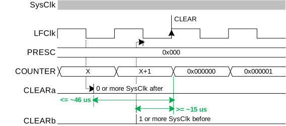
Figure 12. Timing diagram - DELAY_STOP 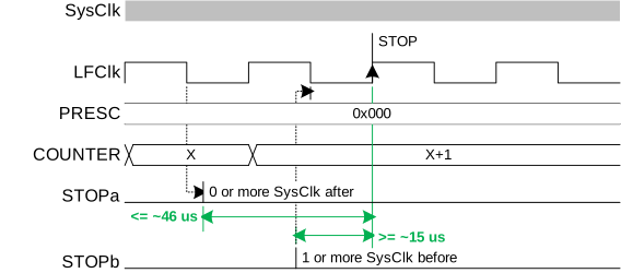
- The START task will start the RTC. Assuming that the LFCLK was previously running and stable,
the first increment of COUNTER (and instance of TICK event) will be typically after 30.5 μs +/-15 μs.
In some cases, in particular if the RTC is STARTed before the LFCLK is running, that timing can be up
to ~250 μs. The software should therefore wait for the first TICK if it has to make sure the RTC is running.
Sending a TRIGOVRFLW task sets the COUNTER to a value close to overflow.
However, since the update of COUNTER relies on a stable LFCLK, sending this task while LFCLK is
not running will start LFCLK, but the update will then be delayed by the same amount of time of
up to ~250 us.
The figures show the smallest and largest delays to on the START task which appears as a +/-15 μs
jitter on the first COUNTER increment.br
Figure 13. Timing diagram - JITTER_START- 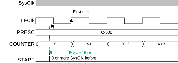
Figure 14. Timing diagram - JITTER_START+ 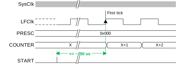
Reading the COUNTER register
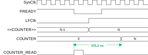
To read the COUNTER register, the internal <<COUNTER>> value is sampled.
To ensure that the <<COUNTER>> is safely sampled (considering an LFCLK transition may occur during a read), the CPU and core memory bus are halted for three cycles by lowering the core PREADY signal. The Read takes the CPU 2 cycles in addition resulting in the COUNTER register read taking a fixed five PCLK16M clock cycles.
Registers
| Base address | Peripheral | Instance | Description | Configuration | |
|---|---|---|---|---|---|
| 0x4000B000 | RTC | RTC0 | Real-time counter 0 | CC[0..2] implemented, CC[3] not implemented | |
| 0x40011000 | RTC | RTC1 | Real-time counter 1 | CC[0..3] implemented | |
| 0x40024000 | RTC | RTC2 | Real-time counter 2 | CC[0..3] implemented | |
| Register | Offset | Description | |
|---|---|---|---|
| TASKS_START | 0x000 | Start RTC COUNTER | |
| TASKS_STOP | 0x004 | Stop RTC COUNTER | |
| TASKS_CLEAR | 0x008 | Clear RTC COUNTER | |
| TASKS_TRIGOVRFLW | 0x00C | Set COUNTER to 0xFFFFF0 | |
| EVENTS_TICK | 0x100 | Event on COUNTER increment | |
| EVENTS_OVRFLW | 0x104 | Event on COUNTER overflow | |
| EVENTS_COMPARE[0] | 0x140 | Compare event on CC[0] match | |
| EVENTS_COMPARE[1] | 0x144 | Compare event on CC[1] match | |
| EVENTS_COMPARE[2] | 0x148 | Compare event on CC[2] match | |
| EVENTS_COMPARE[3] | 0x14C | Compare event on CC[3] match | |
| INTENSET | 0x304 | Enable interrupt | |
| INTENCLR | 0x308 | Disable interrupt | |
| EVTEN | 0x340 | Enable or disable event routing | |
| EVTENSET | 0x344 | Enable event routing | |
| EVTENCLR | 0x348 | Disable event routing | |
| COUNTER | 0x504 | Current COUNTER value | |
| PRESCALER | 0x508 | 12 bit prescaler for COUNTER frequency (32768/(PRESCALER+1)).Must be written when RTC is stopped | |
| CC[0] | 0x540 | Compare register 0 | |
| CC[1] | 0x544 | Compare register 1 | |
| CC[2] | 0x548 | Compare register 2 | |
| CC[3] | 0x54C | Compare register 3 | |
INTENSET
Address offset: 0x304
Enable interrupt
| Bit number | 31 | 30 | 29 | 28 | 27 | 26 | 25 | 24 | 23 | 22 | 21 | 20 | 19 | 18 | 17 | 16 | 15 | 14 | 13 | 12 | 11 | 10 | 9 | 8 | 7 | 6 | 5 | 4 | 3 | 2 | 1 | 0 | |||
|---|---|---|---|---|---|---|---|---|---|---|---|---|---|---|---|---|---|---|---|---|---|---|---|---|---|---|---|---|---|---|---|---|---|---|---|
| Id | F | E | D | C | B | A | |||||||||||||||||||||||||||||
| Reset 0x00000000 | 0 | 0 | 0 | 0 | 0 | 0 | 0 | 0 | 0 | 0 | 0 | 0 | 0 | 0 | 0 | 0 | 0 | 0 | 0 | 0 | 0 | 0 | 0 | 0 | 0 | 0 | 0 | 0 | 0 | 0 | 0 | 0 | |||
| Id | RW | Field | Value Id | Value | Description | ||||||||||||||||||||||||||||||
| A | RW | TICK | Write '1' to Enable interrupt for TICK event See EVENTS_TICK | ||||||||||||||||||||||||||||||||
Set | 1 | Enable | |||||||||||||||||||||||||||||||||
Disabled | 0 | Read: Disabled | |||||||||||||||||||||||||||||||||
Enabled | 1 | Read: Enabled | |||||||||||||||||||||||||||||||||
| B | RW | OVRFLW | Write '1' to Enable interrupt for OVRFLW event See EVENTS_OVRFLW | ||||||||||||||||||||||||||||||||
Set | 1 | Enable | |||||||||||||||||||||||||||||||||
Disabled | 0 | Read: Disabled | |||||||||||||||||||||||||||||||||
Enabled | 1 | Read: Enabled | |||||||||||||||||||||||||||||||||
| C | RW | COMPARE0 | Write '1' to Enable interrupt for COMPARE[0] event | ||||||||||||||||||||||||||||||||
Set | 1 | Enable | |||||||||||||||||||||||||||||||||
Disabled | 0 | Read: Disabled | |||||||||||||||||||||||||||||||||
Enabled | 1 | Read: Enabled | |||||||||||||||||||||||||||||||||
| D | RW | COMPARE1 | Write '1' to Enable interrupt for COMPARE[1] event | ||||||||||||||||||||||||||||||||
Set | 1 | Enable | |||||||||||||||||||||||||||||||||
Disabled | 0 | Read: Disabled | |||||||||||||||||||||||||||||||||
Enabled | 1 | Read: Enabled | |||||||||||||||||||||||||||||||||
| E | RW | COMPARE2 | Write '1' to Enable interrupt for COMPARE[2] event | ||||||||||||||||||||||||||||||||
Set | 1 | Enable | |||||||||||||||||||||||||||||||||
Disabled | 0 | Read: Disabled | |||||||||||||||||||||||||||||||||
Enabled | 1 | Read: Enabled | |||||||||||||||||||||||||||||||||
| F | RW | COMPARE3 | Write '1' to Enable interrupt for COMPARE[3] event | ||||||||||||||||||||||||||||||||
Set | 1 | Enable | |||||||||||||||||||||||||||||||||
Disabled | 0 | Read: Disabled | |||||||||||||||||||||||||||||||||
Enabled | 1 | Read: Enabled | |||||||||||||||||||||||||||||||||
INTENCLR
Address offset: 0x308
Disable interrupt
| Bit number | 31 | 30 | 29 | 28 | 27 | 26 | 25 | 24 | 23 | 22 | 21 | 20 | 19 | 18 | 17 | 16 | 15 | 14 | 13 | 12 | 11 | 10 | 9 | 8 | 7 | 6 | 5 | 4 | 3 | 2 | 1 | 0 | |||
|---|---|---|---|---|---|---|---|---|---|---|---|---|---|---|---|---|---|---|---|---|---|---|---|---|---|---|---|---|---|---|---|---|---|---|---|
| Id | F | E | D | C | B | A | |||||||||||||||||||||||||||||
| Reset 0x00000000 | 0 | 0 | 0 | 0 | 0 | 0 | 0 | 0 | 0 | 0 | 0 | 0 | 0 | 0 | 0 | 0 | 0 | 0 | 0 | 0 | 0 | 0 | 0 | 0 | 0 | 0 | 0 | 0 | 0 | 0 | 0 | 0 | |||
| Id | RW | Field | Value Id | Value | Description | ||||||||||||||||||||||||||||||
| A | RW | TICK | Write '1' to Disable interrupt for TICK event See EVENTS_TICK | ||||||||||||||||||||||||||||||||
Clear | 1 | Disable | |||||||||||||||||||||||||||||||||
Disabled | 0 | Read: Disabled | |||||||||||||||||||||||||||||||||
Enabled | 1 | Read: Enabled | |||||||||||||||||||||||||||||||||
| B | RW | OVRFLW | Write '1' to Disable interrupt for OVRFLW event See EVENTS_OVRFLW | ||||||||||||||||||||||||||||||||
Clear | 1 | Disable | |||||||||||||||||||||||||||||||||
Disabled | 0 | Read: Disabled | |||||||||||||||||||||||||||||||||
Enabled | 1 | Read: Enabled | |||||||||||||||||||||||||||||||||
| C | RW | COMPARE0 | Write '1' to Disable interrupt for COMPARE[0] event | ||||||||||||||||||||||||||||||||
Clear | 1 | Disable | |||||||||||||||||||||||||||||||||
Disabled | 0 | Read: Disabled | |||||||||||||||||||||||||||||||||
Enabled | 1 | Read: Enabled | |||||||||||||||||||||||||||||||||
| D | RW | COMPARE1 | Write '1' to Disable interrupt for COMPARE[1] event | ||||||||||||||||||||||||||||||||
Clear | 1 | Disable | |||||||||||||||||||||||||||||||||
Disabled | 0 | Read: Disabled | |||||||||||||||||||||||||||||||||
Enabled | 1 | Read: Enabled | |||||||||||||||||||||||||||||||||
| E | RW | COMPARE2 | Write '1' to Disable interrupt for COMPARE[2] event | ||||||||||||||||||||||||||||||||
Clear | 1 | Disable | |||||||||||||||||||||||||||||||||
Disabled | 0 | Read: Disabled | |||||||||||||||||||||||||||||||||
Enabled | 1 | Read: Enabled | |||||||||||||||||||||||||||||||||
| F | RW | COMPARE3 | Write '1' to Disable interrupt for COMPARE[3] event | ||||||||||||||||||||||||||||||||
Clear | 1 | Disable | |||||||||||||||||||||||||||||||||
Disabled | 0 | Read: Disabled | |||||||||||||||||||||||||||||||||
Enabled | 1 | Read: Enabled | |||||||||||||||||||||||||||||||||
EVTEN
Address offset: 0x340
Enable or disable event routing
| Bit number | 31 | 30 | 29 | 28 | 27 | 26 | 25 | 24 | 23 | 22 | 21 | 20 | 19 | 18 | 17 | 16 | 15 | 14 | 13 | 12 | 11 | 10 | 9 | 8 | 7 | 6 | 5 | 4 | 3 | 2 | 1 | 0 | |||
|---|---|---|---|---|---|---|---|---|---|---|---|---|---|---|---|---|---|---|---|---|---|---|---|---|---|---|---|---|---|---|---|---|---|---|---|
| Id | F | E | D | C | B | A | |||||||||||||||||||||||||||||
| Reset 0x00000000 | 0 | 0 | 0 | 0 | 0 | 0 | 0 | 0 | 0 | 0 | 0 | 0 | 0 | 0 | 0 | 0 | 0 | 0 | 0 | 0 | 0 | 0 | 0 | 0 | 0 | 0 | 0 | 0 | 0 | 0 | 0 | 0 | |||
| Id | RW | Field | Value Id | Value | Description | ||||||||||||||||||||||||||||||
| A | RW | TICK | Enable or disable event routing for TICK event See EVENTS_TICK | ||||||||||||||||||||||||||||||||
Disabled | 0 | Disable | |||||||||||||||||||||||||||||||||
Enabled | 1 | Enable | |||||||||||||||||||||||||||||||||
| B | RW | OVRFLW | Enable or disable event routing for OVRFLW event See EVENTS_OVRFLW | ||||||||||||||||||||||||||||||||
Disabled | 0 | Disable | |||||||||||||||||||||||||||||||||
Enabled | 1 | Enable | |||||||||||||||||||||||||||||||||
| C | RW | COMPARE0 | Enable or disable event routing for COMPARE[0] event | ||||||||||||||||||||||||||||||||
Disabled | 0 | Disable | |||||||||||||||||||||||||||||||||
Enabled | 1 | Enable | |||||||||||||||||||||||||||||||||
| D | RW | COMPARE1 | Enable or disable event routing for COMPARE[1] event | ||||||||||||||||||||||||||||||||
Disabled | 0 | Disable | |||||||||||||||||||||||||||||||||
Enabled | 1 | Enable | |||||||||||||||||||||||||||||||||
| E | RW | COMPARE2 | Enable or disable event routing for COMPARE[2] event | ||||||||||||||||||||||||||||||||
Disabled | 0 | Disable | |||||||||||||||||||||||||||||||||
Enabled | 1 | Enable | |||||||||||||||||||||||||||||||||
| F | RW | COMPARE3 | Enable or disable event routing for COMPARE[3] event | ||||||||||||||||||||||||||||||||
Disabled | 0 | Disable | |||||||||||||||||||||||||||||||||
Enabled | 1 | Enable | |||||||||||||||||||||||||||||||||
EVTENSET
Address offset: 0x344
Enable event routing
| Bit number | 31 | 30 | 29 | 28 | 27 | 26 | 25 | 24 | 23 | 22 | 21 | 20 | 19 | 18 | 17 | 16 | 15 | 14 | 13 | 12 | 11 | 10 | 9 | 8 | 7 | 6 | 5 | 4 | 3 | 2 | 1 | 0 | |||
|---|---|---|---|---|---|---|---|---|---|---|---|---|---|---|---|---|---|---|---|---|---|---|---|---|---|---|---|---|---|---|---|---|---|---|---|
| Id | F | E | D | C | B | A | |||||||||||||||||||||||||||||
| Reset 0x00000000 | 0 | 0 | 0 | 0 | 0 | 0 | 0 | 0 | 0 | 0 | 0 | 0 | 0 | 0 | 0 | 0 | 0 | 0 | 0 | 0 | 0 | 0 | 0 | 0 | 0 | 0 | 0 | 0 | 0 | 0 | 0 | 0 | |||
| Id | RW | Field | Value Id | Value | Description | ||||||||||||||||||||||||||||||
| A | RW | TICK | Write '1' to Enable event routing for TICK event See EVENTS_TICK | ||||||||||||||||||||||||||||||||
Set | 1 | Enable | |||||||||||||||||||||||||||||||||
Disabled | 0 | Read: Disabled | |||||||||||||||||||||||||||||||||
Enabled | 1 | Read: Enabled | |||||||||||||||||||||||||||||||||
| B | RW | OVRFLW | Write '1' to Enable event routing for OVRFLW event See EVENTS_OVRFLW | ||||||||||||||||||||||||||||||||
Set | 1 | Enable | |||||||||||||||||||||||||||||||||
Disabled | 0 | Read: Disabled | |||||||||||||||||||||||||||||||||
Enabled | 1 | Read: Enabled | |||||||||||||||||||||||||||||||||
| C | RW | COMPARE0 | Write '1' to Enable event routing for COMPARE[0] event | ||||||||||||||||||||||||||||||||
Set | 1 | Enable | |||||||||||||||||||||||||||||||||
Disabled | 0 | Read: Disabled | |||||||||||||||||||||||||||||||||
Enabled | 1 | Read: Enabled | |||||||||||||||||||||||||||||||||
| D | RW | COMPARE1 | Write '1' to Enable event routing for COMPARE[1] event | ||||||||||||||||||||||||||||||||
Set | 1 | Enable | |||||||||||||||||||||||||||||||||
Disabled | 0 | Read: Disabled | |||||||||||||||||||||||||||||||||
Enabled | 1 | Read: Enabled | |||||||||||||||||||||||||||||||||
| E | RW | COMPARE2 | Write '1' to Enable event routing for COMPARE[2] event | ||||||||||||||||||||||||||||||||
Set | 1 | Enable | |||||||||||||||||||||||||||||||||
Disabled | 0 | Read: Disabled | |||||||||||||||||||||||||||||||||
Enabled | 1 | Read: Enabled | |||||||||||||||||||||||||||||||||
| F | RW | COMPARE3 | Write '1' to Enable event routing for COMPARE[3] event | ||||||||||||||||||||||||||||||||
Set | 1 | Enable | |||||||||||||||||||||||||||||||||
Disabled | 0 | Read: Disabled | |||||||||||||||||||||||||||||||||
Enabled | 1 | Read: Enabled | |||||||||||||||||||||||||||||||||
EVTENCLR
Address offset: 0x348
Disable event routing
| Bit number | 31 | 30 | 29 | 28 | 27 | 26 | 25 | 24 | 23 | 22 | 21 | 20 | 19 | 18 | 17 | 16 | 15 | 14 | 13 | 12 | 11 | 10 | 9 | 8 | 7 | 6 | 5 | 4 | 3 | 2 | 1 | 0 | |||
|---|---|---|---|---|---|---|---|---|---|---|---|---|---|---|---|---|---|---|---|---|---|---|---|---|---|---|---|---|---|---|---|---|---|---|---|
| Id | F | E | D | C | B | A | |||||||||||||||||||||||||||||
| Reset 0x00000000 | 0 | 0 | 0 | 0 | 0 | 0 | 0 | 0 | 0 | 0 | 0 | 0 | 0 | 0 | 0 | 0 | 0 | 0 | 0 | 0 | 0 | 0 | 0 | 0 | 0 | 0 | 0 | 0 | 0 | 0 | 0 | 0 | |||
| Id | RW | Field | Value Id | Value | Description | ||||||||||||||||||||||||||||||
| A | RW | TICK | Write '1' to Disable event routing for TICK event See EVENTS_TICK | ||||||||||||||||||||||||||||||||
Clear | 1 | Disable | |||||||||||||||||||||||||||||||||
Disabled | 0 | Read: Disabled | |||||||||||||||||||||||||||||||||
Enabled | 1 | Read: Enabled | |||||||||||||||||||||||||||||||||
| B | RW | OVRFLW | Write '1' to Disable event routing for OVRFLW event See EVENTS_OVRFLW | ||||||||||||||||||||||||||||||||
Clear | 1 | Disable | |||||||||||||||||||||||||||||||||
Disabled | 0 | Read: Disabled | |||||||||||||||||||||||||||||||||
Enabled | 1 | Read: Enabled | |||||||||||||||||||||||||||||||||
| C | RW | COMPARE0 | Write '1' to Disable event routing for COMPARE[0] event | ||||||||||||||||||||||||||||||||
Clear | 1 | Disable | |||||||||||||||||||||||||||||||||
Disabled | 0 | Read: Disabled | |||||||||||||||||||||||||||||||||
Enabled | 1 | Read: Enabled | |||||||||||||||||||||||||||||||||
| D | RW | COMPARE1 | Write '1' to Disable event routing for COMPARE[1] event | ||||||||||||||||||||||||||||||||
Clear | 1 | Disable | |||||||||||||||||||||||||||||||||
Disabled | 0 | Read: Disabled | |||||||||||||||||||||||||||||||||
Enabled | 1 | Read: Enabled | |||||||||||||||||||||||||||||||||
| E | RW | COMPARE2 | Write '1' to Disable event routing for COMPARE[2] event | ||||||||||||||||||||||||||||||||
Clear | 1 | Disable | |||||||||||||||||||||||||||||||||
Disabled | 0 | Read: Disabled | |||||||||||||||||||||||||||||||||
Enabled | 1 | Read: Enabled | |||||||||||||||||||||||||||||||||
| F | RW | COMPARE3 | Write '1' to Disable event routing for COMPARE[3] event | ||||||||||||||||||||||||||||||||
Clear | 1 | Disable | |||||||||||||||||||||||||||||||||
Disabled | 0 | Read: Disabled | |||||||||||||||||||||||||||||||||
Enabled | 1 | Read: Enabled | |||||||||||||||||||||||||||||||||
COUNTER
Address offset: 0x504
Current COUNTER value
| Bit number | 31 | 30 | 29 | 28 | 27 | 26 | 25 | 24 | 23 | 22 | 21 | 20 | 19 | 18 | 17 | 16 | 15 | 14 | 13 | 12 | 11 | 10 | 9 | 8 | 7 | 6 | 5 | 4 | 3 | 2 | 1 | 0 | |||
|---|---|---|---|---|---|---|---|---|---|---|---|---|---|---|---|---|---|---|---|---|---|---|---|---|---|---|---|---|---|---|---|---|---|---|---|
| Id | A | A | A | A | A | A | A | A | A | A | A | A | A | A | A | A | A | A | A | A | A | A | A | A | |||||||||||
| Reset 0x00000000 | 0 | 0 | 0 | 0 | 0 | 0 | 0 | 0 | 0 | 0 | 0 | 0 | 0 | 0 | 0 | 0 | 0 | 0 | 0 | 0 | 0 | 0 | 0 | 0 | 0 | 0 | 0 | 0 | 0 | 0 | 0 | 0 | |||
| Id | RW | Field | Value Id | Value | Description | ||||||||||||||||||||||||||||||
| A | R | COUNTER | Counter value | ||||||||||||||||||||||||||||||||
PRESCALER
Address offset: 0x508
12 bit prescaler for COUNTER frequency (32768/(PRESCALER+1)).Must be written when RTC is stopped
| Bit number | 31 | 30 | 29 | 28 | 27 | 26 | 25 | 24 | 23 | 22 | 21 | 20 | 19 | 18 | 17 | 16 | 15 | 14 | 13 | 12 | 11 | 10 | 9 | 8 | 7 | 6 | 5 | 4 | 3 | 2 | 1 | 0 | |||
|---|---|---|---|---|---|---|---|---|---|---|---|---|---|---|---|---|---|---|---|---|---|---|---|---|---|---|---|---|---|---|---|---|---|---|---|
| Id | A | A | A | A | A | A | A | A | A | A | A | A | |||||||||||||||||||||||
| Reset 0x00000000 | 0 | 0 | 0 | 0 | 0 | 0 | 0 | 0 | 0 | 0 | 0 | 0 | 0 | 0 | 0 | 0 | 0 | 0 | 0 | 0 | 0 | 0 | 0 | 0 | 0 | 0 | 0 | 0 | 0 | 0 | 0 | 0 | |||
| Id | RW | Field | Value Id | Value | Description | ||||||||||||||||||||||||||||||
| A | RW | PRESCALER | Prescaler value | ||||||||||||||||||||||||||||||||
CC[0]
Address offset: 0x540
Compare register 0
| Bit number | 31 | 30 | 29 | 28 | 27 | 26 | 25 | 24 | 23 | 22 | 21 | 20 | 19 | 18 | 17 | 16 | 15 | 14 | 13 | 12 | 11 | 10 | 9 | 8 | 7 | 6 | 5 | 4 | 3 | 2 | 1 | 0 | |||
|---|---|---|---|---|---|---|---|---|---|---|---|---|---|---|---|---|---|---|---|---|---|---|---|---|---|---|---|---|---|---|---|---|---|---|---|
| Id | A | A | A | A | A | A | A | A | A | A | A | A | A | A | A | A | A | A | A | A | A | A | A | A | |||||||||||
| Reset 0x00000000 | 0 | 0 | 0 | 0 | 0 | 0 | 0 | 0 | 0 | 0 | 0 | 0 | 0 | 0 | 0 | 0 | 0 | 0 | 0 | 0 | 0 | 0 | 0 | 0 | 0 | 0 | 0 | 0 | 0 | 0 | 0 | 0 | |||
| Id | RW | Field | Value Id | Value | Description | ||||||||||||||||||||||||||||||
| A | RW | COMPARE | Compare value | ||||||||||||||||||||||||||||||||
CC[1]
Address offset: 0x544
Compare register 1
| Bit number | 31 | 30 | 29 | 28 | 27 | 26 | 25 | 24 | 23 | 22 | 21 | 20 | 19 | 18 | 17 | 16 | 15 | 14 | 13 | 12 | 11 | 10 | 9 | 8 | 7 | 6 | 5 | 4 | 3 | 2 | 1 | 0 | |||
|---|---|---|---|---|---|---|---|---|---|---|---|---|---|---|---|---|---|---|---|---|---|---|---|---|---|---|---|---|---|---|---|---|---|---|---|
| Id | A | A | A | A | A | A | A | A | A | A | A | A | A | A | A | A | A | A | A | A | A | A | A | A | |||||||||||
| Reset 0x00000000 | 0 | 0 | 0 | 0 | 0 | 0 | 0 | 0 | 0 | 0 | 0 | 0 | 0 | 0 | 0 | 0 | 0 | 0 | 0 | 0 | 0 | 0 | 0 | 0 | 0 | 0 | 0 | 0 | 0 | 0 | 0 | 0 | |||
| Id | RW | Field | Value Id | Value | Description | ||||||||||||||||||||||||||||||
| A | RW | COMPARE | Compare value | ||||||||||||||||||||||||||||||||
CC[2]
Address offset: 0x548
Compare register 2
| Bit number | 31 | 30 | 29 | 28 | 27 | 26 | 25 | 24 | 23 | 22 | 21 | 20 | 19 | 18 | 17 | 16 | 15 | 14 | 13 | 12 | 11 | 10 | 9 | 8 | 7 | 6 | 5 | 4 | 3 | 2 | 1 | 0 | |||
|---|---|---|---|---|---|---|---|---|---|---|---|---|---|---|---|---|---|---|---|---|---|---|---|---|---|---|---|---|---|---|---|---|---|---|---|
| Id | A | A | A | A | A | A | A | A | A | A | A | A | A | A | A | A | A | A | A | A | A | A | A | A | |||||||||||
| Reset 0x00000000 | 0 | 0 | 0 | 0 | 0 | 0 | 0 | 0 | 0 | 0 | 0 | 0 | 0 | 0 | 0 | 0 | 0 | 0 | 0 | 0 | 0 | 0 | 0 | 0 | 0 | 0 | 0 | 0 | 0 | 0 | 0 | 0 | |||
| Id | RW | Field | Value Id | Value | Description | ||||||||||||||||||||||||||||||
| A | RW | COMPARE | Compare value | ||||||||||||||||||||||||||||||||
CC[3]
Address offset: 0x54C
Compare register 3
| Bit number | 31 | 30 | 29 | 28 | 27 | 26 | 25 | 24 | 23 | 22 | 21 | 20 | 19 | 18 | 17 | 16 | 15 | 14 | 13 | 12 | 11 | 10 | 9 | 8 | 7 | 6 | 5 | 4 | 3 | 2 | 1 | 0 | |||
|---|---|---|---|---|---|---|---|---|---|---|---|---|---|---|---|---|---|---|---|---|---|---|---|---|---|---|---|---|---|---|---|---|---|---|---|
| Id | A | A | A | A | A | A | A | A | A | A | A | A | A | A | A | A | A | A | A | A | A | A | A | A | |||||||||||
| Reset 0x00000000 | 0 | 0 | 0 | 0 | 0 | 0 | 0 | 0 | 0 | 0 | 0 | 0 | 0 | 0 | 0 | 0 | 0 | 0 | 0 | 0 | 0 | 0 | 0 | 0 | 0 | 0 | 0 | 0 | 0 | 0 | 0 | 0 | |||
| Id | RW | Field | Value Id | Value | Description | ||||||||||||||||||||||||||||||
| A | RW | COMPARE | Compare value | ||||||||||||||||||||||||||||||||
Electrical specification
RTC Electrical Specification
| Symbol | Description | Min. | Typ. | Max. | Units | ||||
|---|---|---|---|---|---|---|---|---|---|
| IRTC | Run current Real Time Counter (LFCLK source) | 0.1 | µA |