CCM — AES CCM mode encryption
Cipher block chaining - message authentication code (CCM) mode is an authenticated encryption algorithm designed to provide both authentication and confidentiality during data transfer. CCM combines counter mode encryption and CBC-MAC authentication. The CCM terminology "Message authentication code (MAC)" is called the "Message integrity check (MIC)" in 'Bluetooth terminology and also in this document.
The CCM block generates an encrypted keystream that is applied to input data using the XOR operation and generates the 4 byte MIC field in one operation. The CCM and radio can be configured to work synchronously. The CCM will encrypt in time for transmission and decrypt after receiving bytes into memory from the Radio. All operations can complete within the packet RX or TX time. CCM on this device is implemented according to Bluetooth requirements and the algorithm as defined in IETF RFC3610, and depends on the AES-128 block cipher. A description of the CCM algorithm can also be found in NIST Special Publication 800-38C. The Bluetooth specification describes the configuration of counter mode blocks and encryption blocks to implement compliant encryption for BLE.
The CCM block uses EasyDMA to load key, counter mode blocks (including the nonce required), and to read/write plain text and cipher text.
The AES CCM supports three operations: key-stream generation, packet encryption, and packet decryption. All these operations are done in compliance with the Bluetooth specification.1A new key-stream must be generated before a new packet encryption or packet decryption operation can be started.
A key-stream is generated by triggering the KSGEN task. An ENDKSGEN event will be generated when the new key-stream has been generated. The key-stream will be stored in the AES CCM’s temporary memory area, specified by the SCRATCHPTR, where it will be used in subsequent encryption and decryption operations.
Encryption is started by triggering the CRYPT task with the MODE register set to ENCRYPTION. Similarly, decryption is started by triggering the same task with MODE set to DECRYPTION. An ENDCRYPT event will be generated when packet encryption is completed as well as when packet decryption is completed, see Figure 1.

Key-stream generation, packet encryption, and packet decryption operations utilize the configuration specified in the data structure pointed to by the CNFPTR pointer. It is necessary to configure this pointer and its underlying data structure, and the MODE register before the KSGEN task is triggered. It is also necessary to configure the INPTR pointer and the OUTPTR pointer before the CRYPT task is triggered.
If a shortcut is used between ENDKSGEN event and CRYPT task, the INPTR pointer and the OUTPTR pointer must be configured before the KSGEN task is triggered.
The AES CCM supports different packet lengths, this is configured via the PACKETLENGTH field in the MODE register.
Shared resources
The CCM shares registers and other resources with other peripherals that have the same ID as the CCM. The user must therefore disable all peripherals that have the same ID as the CCM before the CCM can be configured and used.
Disabling a peripheral that have the same ID as the CCM will not reset any of the registers that are shared with the CCM. It is therefore important to configure all relevant CCM registers explicitly to secure that it operates correctly.
See the Instantiation table in Instantiation for details on peripherals and their IDs.
Encryption
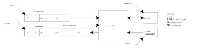
During packet encryption, the AES CCM will read the unencrypted packet located in RAM at the address specified in the INPTR pointer, encrypt the packet and append a four byte long Message Integrity Check (MIC) field to the packet.
The AES CCM will also modify the length field of the packet to adjust for the appended MIC field, that is, add four bytes to the length, and store the resulting packet back into RAM at the address specified in the OUTPTR pointer, see Figure 2.
Empty packets (length field is set to 0) will not be encrypted but instead moved unmodified through the AES CCM.
Decryption
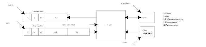
During packet decryption, the AES CCM will read the encrypted packet located in RAM at the address specified in the INPTR pointer, decrypt the packet, authenticate the packet’s MIC field and generate the appropriate MIC status.
The AES CCM will also modify the length field of the packet to adjust for the MIC field, that is, subtract four bytes from the length, and then store the decrypted packet into RAM at the address pointed to by the OUTPTR pointer, see Figure 3.
The CCM is only able to decrypt packets that are at least 5 bytes long, that is, 1 byte or more encrypted payload (EPL) and 4 bytes of MIC. The CCM will therefore generate a MIC error for packets where the length field is set to 1, 2, 3 or 4.
Empty packets (length field is set to 0) will not be decrypted but instead moved unmodified through the AES CCM, these packets will always pass the MIC check.
AES CCM and RADIO concurrent operation
The AES CCM is designed to run in parallel with the RADIO to enable on-the-fly encryption and decryption of RADIO packets without CPU involvement. To facilitate this, the RADIO has to be configured with specific settings.
| Radio parameter | Value | Description |
|---|---|---|
| PCNF0.S0LEN | 1 | Length of HEADER field in: Table 3 and Table 4. |
| PCNF0.LFLEN | 5 or 8 | Length of LENGTH field in: Table 3 and Table 4. |
| PCNF0.S1LEN | 3 or 0 | Length of the RFU field in: Table 3 and Table 4. The combined length of LENGTH and RFU must always be 8 bit. |
| PCNF0.S1 | Include | Always include the S1 field (RFU field) in RAM to secure that the same data structure can be used for PCNF0.S1LEN = 3 and PCNF0.S1LEN = 0: Table 3 and Table 4. |
| MODE | Ble_1Mbit | Data rate. Must match CCM->MODE.DATARATE |
| PCNF1.BALEN | 3 | Length of address (32 bit) |
| CRCCNF.LEN | 3 | Length of CRC (24 bit) |
Encrypting packets on-the-fly in radio transmit mode
When the AES CCM is encrypting a packet on-the-fly at the same time as the RADIO is transmitting it, the RADIO must read the encrypted packet from the same memory location as the AES CCM is writing to.
The OUTPTR pointer in the AES CCM must therefore point to the same memory location as the PACKETPTR pointer in the RADIO, see Figure 4.
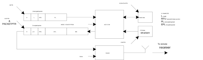
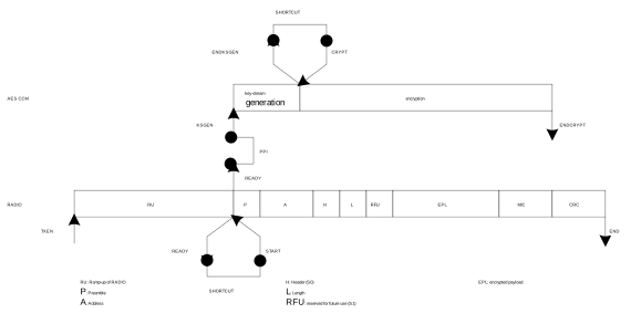
In order to match the RADIO’s timing, the KSGEN task must be triggered no later than when the START task in the RADIO is triggered, in addition the shortcut between the ENDKSGEN event and the CRYPT task must be enabled. This use-case is illustrated in Figure 5 using a PPI connection between the READY event in the RADIO and the KSGEN task in the AES CCM.
Decrypting packets on-the-fly in radio receive mode
When the AES CCM is decrypting a packet on-the-fly at the same time as the RADIO is receiving it, the AES CCM must read the encrypted packet from the same memory location as the RADIO is writing to.
The INPTR pointer in the AES CCM must therefore point to the same memory location as the PACKETPTR pointer in the RADIO, see Figure 6.
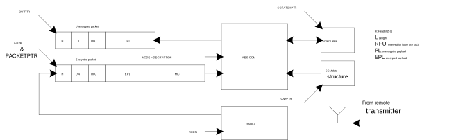
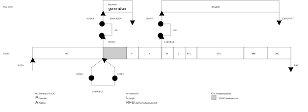
In order to match the RADIO’s timing, the KSGEN task must be triggered no later than when the START task in the RADIO is triggered. In addition, the CRYPT task must be triggered no earlier than when the ADDRESS event is generated by the RADIO.
If the CRYPT task is triggered exactly at the same time as the ADDRESS event is generated by the RADIO, the AES CCM will guarantee that the decryption is completed no later than when the END event in the RADIO is generated.
This use-case is illustrated in Figure 7 using a PPI connection between the ADDRESS event in the RADIO and the CRYPT task in the AES CCM. The KSGEN task is triggered from the READY event in the RADIO through a PPI connection.
CCM data structure
The CCM data structure is located in Data RAM at the memory location specified by the CNFPTR pointer register.
| Property | Address offset | Description |
|---|---|---|
| KEY | 0 | 16 byte AES key |
| PKTCTR | 16 | Octet0 (LSO) of packet counter |
| 17 | Octet1 of packet counter | |
| 18 | Octet2 of packet counter | |
| 19 | Octet3 of packet counter | |
| 20 | Bit 6 – Bit 0: Octet4 (7 most significant bits of packet counter, with Bit 6 being the most significant bit) Bit7: Ignored | |
| 21 | Ignored | |
| 22 | Ignored | |
| 23 | Ignored | |
| 24 | Bit 0: Direction bit Bit 7 – Bit 1: Zero padded | |
| IV | 25 | 8 byte initialization vector (IV) Octet0 (LSO) of IV, Octet1 of IV, … , Octet7 (MSO) of IV |
The NONCE vector (as specified by the Bluetooth Core Specification) will be generated by hardware based on the information specified in the CCM data structure from Table 2 .
| Property | Address offset | Description |
|---|---|---|
| HEADER | 0 | Packet Header |
| LENGTH | 1 | Number of bytes in unencrypted payload |
| RFU | 2 | Reserved Future Use |
| PAYLOAD | 3 | Unencrypted payload |
| Property | Address offset | Description |
|---|---|---|
| HEADER | 0 | Packet Header |
| LENGTH | 1 | Number of bytes in encrypted payload including length of MIC Important: LENGTH will be 0 for empty packets since the MIC is not added to
empty packets |
| RFU | 2 | Reserved Future Use |
| PAYLOAD | 3 | Encrypted payload |
| MIC | 3 + payload length | ENCRYPT: 4 bytes encrypted MIC Important: MIC is not
added to empty packets |
EasyDMA and ERROR event
The CCM implements an EasyDMA mechanism for reading and writing to the RAM.
In some scenarios where the CPU and other DMA enabled peripherals are accessing the RAM at the same time, the CCM DMA could experience some bus conflicts which may also result in an error during encryption. If this happens, the ERROR event will be generated.
The EasyDMA will have finished accessing the RAM when the ENDKSGEN and ENDCRYPT events are generated.
If the CNFPTR, SCRATCHPTR, INPTR and the OUTPTR are not pointing to the Data RAM region, an EasyDMA transfer may result in a HardFault or RAM corruption. See Memory for more information about the different memory regions.
Registers
| Base address | Peripheral | Instance | Description | Configuration | |
|---|---|---|---|---|---|
| 0x4000F000 | CCM | CCM | AES CCM Mode Encryption | ||
| Register | Offset | Description | |
|---|---|---|---|
| TASKS_KSGEN | 0x000 | Start generation of key-stream. This operation will stop by itself when completed. | |
| TASKS_CRYPT | 0x004 | Start encryption/decryption. This operation will stop by itself when completed. | |
| TASKS_STOP | 0x008 | Stop encryption/decryption | |
| EVENTS_ENDKSGEN | 0x100 | Key-stream generation complete | |
| EVENTS_ENDCRYPT | 0x104 | Encrypt/decrypt complete | |
| EVENTS_ERROR | 0x108 | CCM error event | |
| SHORTS | 0x200 | Shortcut register | |
| INTENSET | 0x304 | Enable interrupt | |
| INTENCLR | 0x308 | Disable interrupt | |
| MICSTATUS | 0x400 | MIC check result | |
| ENABLE | 0x500 | Enable | |
| MODE | 0x504 | Operation mode | |
| CNFPTR | 0x508 | Pointer to data structure holding AES key and NONCE vector | |
| INPTR | 0x50C | Input pointer | |
| OUTPTR | 0x510 | Output pointer | |
| SCRATCHPTR | 0x514 | Pointer to data area used for temporary storage | |
SHORTS
Address offset: 0x200
Shortcut register
| Bit number | 31 | 30 | 29 | 28 | 27 | 26 | 25 | 24 | 23 | 22 | 21 | 20 | 19 | 18 | 17 | 16 | 15 | 14 | 13 | 12 | 11 | 10 | 9 | 8 | 7 | 6 | 5 | 4 | 3 | 2 | 1 | 0 | |||
|---|---|---|---|---|---|---|---|---|---|---|---|---|---|---|---|---|---|---|---|---|---|---|---|---|---|---|---|---|---|---|---|---|---|---|---|
| Id | A | ||||||||||||||||||||||||||||||||||
| Reset 0x00000000 | 0 | 0 | 0 | 0 | 0 | 0 | 0 | 0 | 0 | 0 | 0 | 0 | 0 | 0 | 0 | 0 | 0 | 0 | 0 | 0 | 0 | 0 | 0 | 0 | 0 | 0 | 0 | 0 | 0 | 0 | 0 | 0 | |||
| Id | RW | Field | Value Id | Value | Description | ||||||||||||||||||||||||||||||
| A | RW | ENDKSGEN_CRYPT | Shortcut between ENDKSGEN event and CRYPT task See EVENTS_ENDKSGEN and TASKS_CRYPT | ||||||||||||||||||||||||||||||||
Disabled | 0 | Disable shortcut | |||||||||||||||||||||||||||||||||
Enabled | 1 | Enable shortcut | |||||||||||||||||||||||||||||||||
INTENSET
Address offset: 0x304
Enable interrupt
| Bit number | 31 | 30 | 29 | 28 | 27 | 26 | 25 | 24 | 23 | 22 | 21 | 20 | 19 | 18 | 17 | 16 | 15 | 14 | 13 | 12 | 11 | 10 | 9 | 8 | 7 | 6 | 5 | 4 | 3 | 2 | 1 | 0 | |||
|---|---|---|---|---|---|---|---|---|---|---|---|---|---|---|---|---|---|---|---|---|---|---|---|---|---|---|---|---|---|---|---|---|---|---|---|
| Id | C | B | A | ||||||||||||||||||||||||||||||||
| Reset 0x00000000 | 0 | 0 | 0 | 0 | 0 | 0 | 0 | 0 | 0 | 0 | 0 | 0 | 0 | 0 | 0 | 0 | 0 | 0 | 0 | 0 | 0 | 0 | 0 | 0 | 0 | 0 | 0 | 0 | 0 | 0 | 0 | 0 | |||
| Id | RW | Field | Value Id | Value | Description | ||||||||||||||||||||||||||||||
| A | RW | ENDKSGEN | Write '1' to Enable interrupt for ENDKSGEN event See EVENTS_ENDKSGEN | ||||||||||||||||||||||||||||||||
Set | 1 | Enable | |||||||||||||||||||||||||||||||||
Disabled | 0 | Read: Disabled | |||||||||||||||||||||||||||||||||
Enabled | 1 | Read: Enabled | |||||||||||||||||||||||||||||||||
| B | RW | ENDCRYPT | Write '1' to Enable interrupt for ENDCRYPT event See EVENTS_ENDCRYPT | ||||||||||||||||||||||||||||||||
Set | 1 | Enable | |||||||||||||||||||||||||||||||||
Disabled | 0 | Read: Disabled | |||||||||||||||||||||||||||||||||
Enabled | 1 | Read: Enabled | |||||||||||||||||||||||||||||||||
| C | RW | ERROR | Write '1' to Enable interrupt for ERROR event See EVENTS_ERROR | ||||||||||||||||||||||||||||||||
Set | 1 | Enable | |||||||||||||||||||||||||||||||||
Disabled | 0 | Read: Disabled | |||||||||||||||||||||||||||||||||
Enabled | 1 | Read: Enabled | |||||||||||||||||||||||||||||||||
INTENCLR
Address offset: 0x308
Disable interrupt
| Bit number | 31 | 30 | 29 | 28 | 27 | 26 | 25 | 24 | 23 | 22 | 21 | 20 | 19 | 18 | 17 | 16 | 15 | 14 | 13 | 12 | 11 | 10 | 9 | 8 | 7 | 6 | 5 | 4 | 3 | 2 | 1 | 0 | |||
|---|---|---|---|---|---|---|---|---|---|---|---|---|---|---|---|---|---|---|---|---|---|---|---|---|---|---|---|---|---|---|---|---|---|---|---|
| Id | C | B | A | ||||||||||||||||||||||||||||||||
| Reset 0x00000000 | 0 | 0 | 0 | 0 | 0 | 0 | 0 | 0 | 0 | 0 | 0 | 0 | 0 | 0 | 0 | 0 | 0 | 0 | 0 | 0 | 0 | 0 | 0 | 0 | 0 | 0 | 0 | 0 | 0 | 0 | 0 | 0 | |||
| Id | RW | Field | Value Id | Value | Description | ||||||||||||||||||||||||||||||
| A | RW | ENDKSGEN | Write '1' to Disable interrupt for ENDKSGEN event See EVENTS_ENDKSGEN | ||||||||||||||||||||||||||||||||
Clear | 1 | Disable | |||||||||||||||||||||||||||||||||
Disabled | 0 | Read: Disabled | |||||||||||||||||||||||||||||||||
Enabled | 1 | Read: Enabled | |||||||||||||||||||||||||||||||||
| B | RW | ENDCRYPT | Write '1' to Disable interrupt for ENDCRYPT event See EVENTS_ENDCRYPT | ||||||||||||||||||||||||||||||||
Clear | 1 | Disable | |||||||||||||||||||||||||||||||||
Disabled | 0 | Read: Disabled | |||||||||||||||||||||||||||||||||
Enabled | 1 | Read: Enabled | |||||||||||||||||||||||||||||||||
| C | RW | ERROR | Write '1' to Disable interrupt for ERROR event See EVENTS_ERROR | ||||||||||||||||||||||||||||||||
Clear | 1 | Disable | |||||||||||||||||||||||||||||||||
Disabled | 0 | Read: Disabled | |||||||||||||||||||||||||||||||||
Enabled | 1 | Read: Enabled | |||||||||||||||||||||||||||||||||
MICSTATUS
Address offset: 0x400
MIC check result
| Bit number | 31 | 30 | 29 | 28 | 27 | 26 | 25 | 24 | 23 | 22 | 21 | 20 | 19 | 18 | 17 | 16 | 15 | 14 | 13 | 12 | 11 | 10 | 9 | 8 | 7 | 6 | 5 | 4 | 3 | 2 | 1 | 0 | |||
|---|---|---|---|---|---|---|---|---|---|---|---|---|---|---|---|---|---|---|---|---|---|---|---|---|---|---|---|---|---|---|---|---|---|---|---|
| Id | A | ||||||||||||||||||||||||||||||||||
| Reset 0x00000000 | 0 | 0 | 0 | 0 | 0 | 0 | 0 | 0 | 0 | 0 | 0 | 0 | 0 | 0 | 0 | 0 | 0 | 0 | 0 | 0 | 0 | 0 | 0 | 0 | 0 | 0 | 0 | 0 | 0 | 0 | 0 | 0 | |||
| Id | RW | Field | Value Id | Value | Description | ||||||||||||||||||||||||||||||
| A | R | MICSTATUS | The result of the MIC check performed during the previous decryption operation | ||||||||||||||||||||||||||||||||
CheckFailed | 0 | MIC check failed | |||||||||||||||||||||||||||||||||
CheckPassed | 1 | MIC check passed | |||||||||||||||||||||||||||||||||
ENABLE
Address offset: 0x500
Enable
| Bit number | 31 | 30 | 29 | 28 | 27 | 26 | 25 | 24 | 23 | 22 | 21 | 20 | 19 | 18 | 17 | 16 | 15 | 14 | 13 | 12 | 11 | 10 | 9 | 8 | 7 | 6 | 5 | 4 | 3 | 2 | 1 | 0 | |||
|---|---|---|---|---|---|---|---|---|---|---|---|---|---|---|---|---|---|---|---|---|---|---|---|---|---|---|---|---|---|---|---|---|---|---|---|
| Id | A | A | |||||||||||||||||||||||||||||||||
| Reset 0x00000000 | 0 | 0 | 0 | 0 | 0 | 0 | 0 | 0 | 0 | 0 | 0 | 0 | 0 | 0 | 0 | 0 | 0 | 0 | 0 | 0 | 0 | 0 | 0 | 0 | 0 | 0 | 0 | 0 | 0 | 0 | 0 | 0 | |||
| Id | RW | Field | Value Id | Value | Description | ||||||||||||||||||||||||||||||
| A | RW | ENABLE | Enable or disable CCM | ||||||||||||||||||||||||||||||||
Disabled | 0 | Disable | |||||||||||||||||||||||||||||||||
Enabled | 2 | Enable | |||||||||||||||||||||||||||||||||
MODE
Address offset: 0x504
Operation mode
| Bit number | 31 | 30 | 29 | 28 | 27 | 26 | 25 | 24 | 23 | 22 | 21 | 20 | 19 | 18 | 17 | 16 | 15 | 14 | 13 | 12 | 11 | 10 | 9 | 8 | 7 | 6 | 5 | 4 | 3 | 2 | 1 | 0 | |||
|---|---|---|---|---|---|---|---|---|---|---|---|---|---|---|---|---|---|---|---|---|---|---|---|---|---|---|---|---|---|---|---|---|---|---|---|
| Id | C | B | A | ||||||||||||||||||||||||||||||||
| Reset 0x00000001 | 0 | 0 | 0 | 0 | 0 | 0 | 0 | 0 | 0 | 0 | 0 | 0 | 0 | 0 | 0 | 0 | 0 | 0 | 0 | 0 | 0 | 0 | 0 | 0 | 0 | 0 | 0 | 0 | 0 | 0 | 0 | 1 | |||
| Id | RW | Field | Value Id | Value | Description | ||||||||||||||||||||||||||||||
| A | RW | MODE | The mode of operation to be used | ||||||||||||||||||||||||||||||||
Encryption | 0 | AES CCM packet encryption mode | |||||||||||||||||||||||||||||||||
Decryption | 1 | AES CCM packet decryption mode | |||||||||||||||||||||||||||||||||
| B | RW | DATARATE | Data rate that the CCM shall run in synch with | ||||||||||||||||||||||||||||||||
1Mbit | 0 | In synch with 1 Mbit data rate | |||||||||||||||||||||||||||||||||
2Mbit | 1 | In synch with 2 Mbit data rate | |||||||||||||||||||||||||||||||||
| C | RW | LENGTH | Packet length configuration | ||||||||||||||||||||||||||||||||
Default | 0 | Default length. Effective length of LENGTH field is 5-bit | |||||||||||||||||||||||||||||||||
Extended | 1 | Extended length. Effective length of LENGTH field is 8-bit | |||||||||||||||||||||||||||||||||
CNFPTR
Address offset: 0x508
Pointer to data structure holding AES key and NONCE vector
| Bit number | 31 | 30 | 29 | 28 | 27 | 26 | 25 | 24 | 23 | 22 | 21 | 20 | 19 | 18 | 17 | 16 | 15 | 14 | 13 | 12 | 11 | 10 | 9 | 8 | 7 | 6 | 5 | 4 | 3 | 2 | 1 | 0 | |||
|---|---|---|---|---|---|---|---|---|---|---|---|---|---|---|---|---|---|---|---|---|---|---|---|---|---|---|---|---|---|---|---|---|---|---|---|
| Id | A | A | A | A | A | A | A | A | A | A | A | A | A | A | A | A | A | A | A | A | A | A | A | A | A | A | A | A | A | A | A | A | |||
| Reset 0x00000000 | 0 | 0 | 0 | 0 | 0 | 0 | 0 | 0 | 0 | 0 | 0 | 0 | 0 | 0 | 0 | 0 | 0 | 0 | 0 | 0 | 0 | 0 | 0 | 0 | 0 | 0 | 0 | 0 | 0 | 0 | 0 | 0 | |||
| Id | RW | Field | Value Id | Value | Description | ||||||||||||||||||||||||||||||
| A | RW | CNFPTR | Pointer to the data structure holding the AES key and the CCM NONCE vector (see Table 1 CCM data structure overview) | ||||||||||||||||||||||||||||||||
INPTR
Address offset: 0x50C
Input pointer
| Bit number | 31 | 30 | 29 | 28 | 27 | 26 | 25 | 24 | 23 | 22 | 21 | 20 | 19 | 18 | 17 | 16 | 15 | 14 | 13 | 12 | 11 | 10 | 9 | 8 | 7 | 6 | 5 | 4 | 3 | 2 | 1 | 0 | |||
|---|---|---|---|---|---|---|---|---|---|---|---|---|---|---|---|---|---|---|---|---|---|---|---|---|---|---|---|---|---|---|---|---|---|---|---|
| Id | A | A | A | A | A | A | A | A | A | A | A | A | A | A | A | A | A | A | A | A | A | A | A | A | A | A | A | A | A | A | A | A | |||
| Reset 0x00000000 | 0 | 0 | 0 | 0 | 0 | 0 | 0 | 0 | 0 | 0 | 0 | 0 | 0 | 0 | 0 | 0 | 0 | 0 | 0 | 0 | 0 | 0 | 0 | 0 | 0 | 0 | 0 | 0 | 0 | 0 | 0 | 0 | |||
| Id | RW | Field | Value Id | Value | Description | ||||||||||||||||||||||||||||||
| A | RW | INPTR | Input pointer | ||||||||||||||||||||||||||||||||
OUTPTR
Address offset: 0x510
Output pointer
| Bit number | 31 | 30 | 29 | 28 | 27 | 26 | 25 | 24 | 23 | 22 | 21 | 20 | 19 | 18 | 17 | 16 | 15 | 14 | 13 | 12 | 11 | 10 | 9 | 8 | 7 | 6 | 5 | 4 | 3 | 2 | 1 | 0 | |||
|---|---|---|---|---|---|---|---|---|---|---|---|---|---|---|---|---|---|---|---|---|---|---|---|---|---|---|---|---|---|---|---|---|---|---|---|
| Id | A | A | A | A | A | A | A | A | A | A | A | A | A | A | A | A | A | A | A | A | A | A | A | A | A | A | A | A | A | A | A | A | |||
| Reset 0x00000000 | 0 | 0 | 0 | 0 | 0 | 0 | 0 | 0 | 0 | 0 | 0 | 0 | 0 | 0 | 0 | 0 | 0 | 0 | 0 | 0 | 0 | 0 | 0 | 0 | 0 | 0 | 0 | 0 | 0 | 0 | 0 | 0 | |||
| Id | RW | Field | Value Id | Value | Description | ||||||||||||||||||||||||||||||
| A | RW | OUTPTR | Output pointer | ||||||||||||||||||||||||||||||||
SCRATCHPTR
Address offset: 0x514
Pointer to data area used for temporary storage
| Bit number | 31 | 30 | 29 | 28 | 27 | 26 | 25 | 24 | 23 | 22 | 21 | 20 | 19 | 18 | 17 | 16 | 15 | 14 | 13 | 12 | 11 | 10 | 9 | 8 | 7 | 6 | 5 | 4 | 3 | 2 | 1 | 0 | |||
|---|---|---|---|---|---|---|---|---|---|---|---|---|---|---|---|---|---|---|---|---|---|---|---|---|---|---|---|---|---|---|---|---|---|---|---|
| Id | A | A | A | A | A | A | A | A | A | A | A | A | A | A | A | A | A | A | A | A | A | A | A | A | A | A | A | A | A | A | A | A | |||
| Reset 0x00000000 | 0 | 0 | 0 | 0 | 0 | 0 | 0 | 0 | 0 | 0 | 0 | 0 | 0 | 0 | 0 | 0 | 0 | 0 | 0 | 0 | 0 | 0 | 0 | 0 | 0 | 0 | 0 | 0 | 0 | 0 | 0 | 0 | |||
| Id | RW | Field | Value Id | Value | Description | ||||||||||||||||||||||||||||||
| A | RW | SCRATCHPTR | Pointer to a scratch data area used for temporary storage during key-stream generation, MIC generation and encryption/decryption. The scratch area is used for temporary storage of data during key-stream generation and encryption. A space of 43 bytes, or (16 + MAXPACKETSIZE) bytes, whatever is largest, must be reserved in RAM. | ||||||||||||||||||||||||||||||||