UART — Universal asynchronous receiver/transmitter
Functional description
Listed here are the main features of UART.
The UART implements support for the following features:
- Full-duplex operation
- Automatic flow control
- Parity checking and generation for the 9th data bit
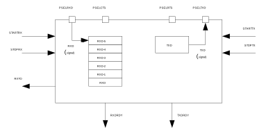
As illustrated in Figure 1, the UART uses the TXD and RXD registers directly to transmit and receive data. The UART uses one stop bit.
Pin configuration
The different signals RXD, CTS (Clear To Send, active low), RTS (Request To Send, active low), and TXD associated with the UART are mapped to physical pins according to the configuration specified in the PSELRXD, PSELCTS, PSELRTS, and PSELTXD registers respectively.
If a value of 0xFFFFFFFF is specified in any of these registers, the associated UART signal will not be connected to any physical pin. The PSELRXD, PSELCTS, PSELRTS, and PSELTXD registers and their configurations are only used as long as the UART is enabled, and retained only for the duration the device is in ON mode. PSELRXD, PSELCTS, PSELRTS and PSELTXD must only be configured when the UART is disabled.
To secure correct signal levels on the pins by the UART when the system is in OFF mode, the pins must be configured in the GPIO peripheral as described in Pin configuration.
Only one peripheral can be assigned to drive a particular GPIO pin at a time. Failing to do so may result in unpredictable behavior.
| UART pin | Direction | Output value |
|---|---|---|
| RXD | Input | Not applicable |
| CTS | Input | Not applicable |
| RTS | Output | 1 |
| TXD | Output | 1 |
Shared resources
The UART shares registers and other resources with other peripherals that have the same ID as the UART.
Therefore, you must disable all peripherals that have the same ID as the UART before the UART can be configured and used. Disabling a peripheral that has the same ID as the UART will not reset any of the registers that are shared with the UART. It is therefore important to configure all relevant UART registers explicitly to ensure that it operates correctly.
See the Instantiation table in Instantiation for details on peripherals and their IDs.
Transmission
A UART transmission sequence is started by triggering the STARTTX task.
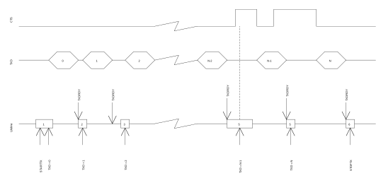
Bytes are transmitted by writing to the TXD register. When a byte has been successfully transmitted the UART will generate a TXDRDY event after which a new byte can be written to the TXD register. A UART transmission sequence is stopped immediately by triggering the STOPTX task.
If flow control is enabled a transmission will be automatically suspended when CTS is deactivated and resumed when CTS is activated again, as illustrated in Figure 2. A byte that is in transmission when CTS is deactivated will be fully transmitted before the transmission is suspended. For more information, see Suspending the UART.
Reception
A UART reception sequence is started by triggering the STARTRX task.
The UART receiver chain implements a FIFO capable of storing six incoming RXD bytes before data is overwritten. Bytes are extracted from this FIFO by reading the RXD register. When a byte is extracted from the FIFO a new byte pending in the FIFO will be moved to the RXD register. The UART will generate an RXDRDY event every time a new byte is moved to the RXD register.
When flow control is enabled, the UART will deactivate the RTS signal when there is only space for four more bytes in the receiver FIFO. The counterpart transmitter is therefore able to send up to four bytes after the RTS signal is deactivated before data is being overwritten. To prevent overwriting data in the FIFO, the counterpart UART transmitter must therefore make sure to stop transmitting data within four bytes after the RTS line is deactivated.
The RTS signal will first be activated again when the FIFO has been emptied, that is, when all bytes in the FIFO have been read by the CPU, see Figure 3.
The RTS signal will also be deactivated when the receiver is stopped through the STOPRX task as illustrated in Figure 3. The UART is able to receive four to five additional bytes if they are sent in succession immediately after the RTS signal has been deactivated. This is possible because the UART is, even after the STOPRX task is triggered, able to receive bytes for an extended period of time dependent on the configured baud rate. The UART will generate a receiver timeout event (RXTO) when this period has elapsed.
To prevent loss of incoming data the RXD register must only be read one time following every RXDRDY event.
To secure that the CPU can detect all incoming RXDRDY events through the RXDRDY event register, the RXDRDY event register must be cleared before the RXD register is read. The reason for this is that the UART is allowed to write a new byte to the RXD register, and therefore can also generate a new event, immediately after the RXD register is read (emptied) by the CPU.
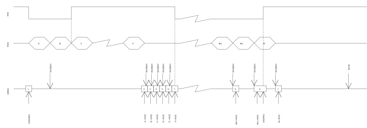
As indicated in occurrence 2 in the figure, the RXDRDY event associated with byte B is generated first after byte A has been extracted from RXD.
Suspending the UART
The UART can be suspended by triggering the SUSPEND task.
SUSPEND will affect both the UART receiver and the UART transmitter, i.e. the transmitter will stop transmitting and the receiver will stop receiving. UART transmission and reception can be resumed, after being suspended, by triggering STARTTX and STARTRX respectively.
Following a SUSPEND task, an ongoing TXD byte transmission will be completed before the UART is suspended.
When the SUSPEND task is triggered, the UART receiver will behave in the same way as it does when the STOPRX task is triggered.
Error conditions
An ERROR event, in the form of a framing error, will be generated if a valid stop bit is not detected in a frame. Another ERROR event, in the form of a break condition, will be generated if the RXD line is held active low for longer than the length of a data frame. Effectively, a framing error is always generated before a break condition occurs.
Using the UART without flow control
If flow control is not enabled, the interface will behave as if the CTS and RTS lines are kept active all the time.
Parity configuration
When parity is enabled, the parity will be generated automatically from the even parity of TXD and RXD for transmission and reception respectively.
Registers
| Base address | Peripheral | Instance | Description | Configuration | |
|---|---|---|---|---|---|
| 0x40002000 | UART | UART0 | Universal Asynchronous Receiver/Transmitter | Deprecated | |
| Register | Offset | Description | |
|---|---|---|---|
| TASKS_STARTRX | 0x000 | Start UART receiver | |
| TASKS_STOPRX | 0x004 | Stop UART receiver | |
| TASKS_STARTTX | 0x008 | Start UART transmitter | |
| TASKS_STOPTX | 0x00C | Stop UART transmitter | |
| TASKS_SUSPEND | 0x01C | Suspend UART | |
| EVENTS_CTS | 0x100 | CTS is activated (set low). Clear To Send. | |
| EVENTS_NCTS | 0x104 | CTS is deactivated (set high). Not Clear To Send. | |
| EVENTS_RXDRDY | 0x108 | Data received in RXD | |
| EVENTS_TXDRDY | 0x11C | Data sent from TXD | |
| EVENTS_ERROR | 0x124 | Error detected | |
| EVENTS_RXTO | 0x144 | Receiver timeout | |
| SHORTS | 0x200 | Shortcut register | |
| INTENSET | 0x304 | Enable interrupt | |
| INTENCLR | 0x308 | Disable interrupt | |
| ERRORSRC | 0x480 | Error source | |
| ENABLE | 0x500 | Enable UART | |
| PSELRTS | 0x508 | Pin select for RTS | |
| PSELTXD | 0x50C | Pin select for TXD | |
| PSELCTS | 0x510 | Pin select for CTS | |
| PSELRXD | 0x514 | Pin select for RXD | |
| RXD | 0x518 | RXD register | |
| TXD | 0x51C | TXD register | |
| BAUDRATE | 0x524 | Baud rate | |
| CONFIG | 0x56C | Configuration of parity and hardware flow control | |
SHORTS
Address offset: 0x200
Shortcut register
| Bit number | 31 | 30 | 29 | 28 | 27 | 26 | 25 | 24 | 23 | 22 | 21 | 20 | 19 | 18 | 17 | 16 | 15 | 14 | 13 | 12 | 11 | 10 | 9 | 8 | 7 | 6 | 5 | 4 | 3 | 2 | 1 | 0 | |||
|---|---|---|---|---|---|---|---|---|---|---|---|---|---|---|---|---|---|---|---|---|---|---|---|---|---|---|---|---|---|---|---|---|---|---|---|
| Id | B | A | |||||||||||||||||||||||||||||||||
| Reset 0x00000000 | 0 | 0 | 0 | 0 | 0 | 0 | 0 | 0 | 0 | 0 | 0 | 0 | 0 | 0 | 0 | 0 | 0 | 0 | 0 | 0 | 0 | 0 | 0 | 0 | 0 | 0 | 0 | 0 | 0 | 0 | 0 | 0 | |||
| Id | RW | Field | Value Id | Value | Description | ||||||||||||||||||||||||||||||
| A | RW | CTS_STARTRX | Shortcut between CTS event and STARTRX task See EVENTS_CTS and TASKS_STARTRX | ||||||||||||||||||||||||||||||||
Disabled | 0 | Disable shortcut | |||||||||||||||||||||||||||||||||
Enabled | 1 | Enable shortcut | |||||||||||||||||||||||||||||||||
| B | RW | NCTS_STOPRX | Shortcut between NCTS event and STOPRX task See EVENTS_NCTS and TASKS_STOPRX | ||||||||||||||||||||||||||||||||
Disabled | 0 | Disable shortcut | |||||||||||||||||||||||||||||||||
Enabled | 1 | Enable shortcut | |||||||||||||||||||||||||||||||||
INTENSET
Address offset: 0x304
Enable interrupt
| Bit number | 31 | 30 | 29 | 28 | 27 | 26 | 25 | 24 | 23 | 22 | 21 | 20 | 19 | 18 | 17 | 16 | 15 | 14 | 13 | 12 | 11 | 10 | 9 | 8 | 7 | 6 | 5 | 4 | 3 | 2 | 1 | 0 | |||
|---|---|---|---|---|---|---|---|---|---|---|---|---|---|---|---|---|---|---|---|---|---|---|---|---|---|---|---|---|---|---|---|---|---|---|---|
| Id | F | E | D | C | B | A | |||||||||||||||||||||||||||||
| Reset 0x00000000 | 0 | 0 | 0 | 0 | 0 | 0 | 0 | 0 | 0 | 0 | 0 | 0 | 0 | 0 | 0 | 0 | 0 | 0 | 0 | 0 | 0 | 0 | 0 | 0 | 0 | 0 | 0 | 0 | 0 | 0 | 0 | 0 | |||
| Id | RW | Field | Value Id | Value | Description | ||||||||||||||||||||||||||||||
| A | RW | CTS | Write '1' to Enable interrupt for CTS event See EVENTS_CTS | ||||||||||||||||||||||||||||||||
Set | 1 | Enable | |||||||||||||||||||||||||||||||||
Disabled | 0 | Read: Disabled | |||||||||||||||||||||||||||||||||
Enabled | 1 | Read: Enabled | |||||||||||||||||||||||||||||||||
| B | RW | NCTS | Write '1' to Enable interrupt for NCTS event See EVENTS_NCTS | ||||||||||||||||||||||||||||||||
Set | 1 | Enable | |||||||||||||||||||||||||||||||||
Disabled | 0 | Read: Disabled | |||||||||||||||||||||||||||||||||
Enabled | 1 | Read: Enabled | |||||||||||||||||||||||||||||||||
| C | RW | RXDRDY | Write '1' to Enable interrupt for RXDRDY event See EVENTS_RXDRDY | ||||||||||||||||||||||||||||||||
Set | 1 | Enable | |||||||||||||||||||||||||||||||||
Disabled | 0 | Read: Disabled | |||||||||||||||||||||||||||||||||
Enabled | 1 | Read: Enabled | |||||||||||||||||||||||||||||||||
| D | RW | TXDRDY | Write '1' to Enable interrupt for TXDRDY event See EVENTS_TXDRDY | ||||||||||||||||||||||||||||||||
Set | 1 | Enable | |||||||||||||||||||||||||||||||||
Disabled | 0 | Read: Disabled | |||||||||||||||||||||||||||||||||
Enabled | 1 | Read: Enabled | |||||||||||||||||||||||||||||||||
| E | RW | ERROR | Write '1' to Enable interrupt for ERROR event See EVENTS_ERROR | ||||||||||||||||||||||||||||||||
Set | 1 | Enable | |||||||||||||||||||||||||||||||||
Disabled | 0 | Read: Disabled | |||||||||||||||||||||||||||||||||
Enabled | 1 | Read: Enabled | |||||||||||||||||||||||||||||||||
| F | RW | RXTO | Write '1' to Enable interrupt for RXTO event See EVENTS_RXTO | ||||||||||||||||||||||||||||||||
Set | 1 | Enable | |||||||||||||||||||||||||||||||||
Disabled | 0 | Read: Disabled | |||||||||||||||||||||||||||||||||
Enabled | 1 | Read: Enabled | |||||||||||||||||||||||||||||||||
INTENCLR
Address offset: 0x308
Disable interrupt
| Bit number | 31 | 30 | 29 | 28 | 27 | 26 | 25 | 24 | 23 | 22 | 21 | 20 | 19 | 18 | 17 | 16 | 15 | 14 | 13 | 12 | 11 | 10 | 9 | 8 | 7 | 6 | 5 | 4 | 3 | 2 | 1 | 0 | |||
|---|---|---|---|---|---|---|---|---|---|---|---|---|---|---|---|---|---|---|---|---|---|---|---|---|---|---|---|---|---|---|---|---|---|---|---|
| Id | F | E | D | C | B | A | |||||||||||||||||||||||||||||
| Reset 0x00000000 | 0 | 0 | 0 | 0 | 0 | 0 | 0 | 0 | 0 | 0 | 0 | 0 | 0 | 0 | 0 | 0 | 0 | 0 | 0 | 0 | 0 | 0 | 0 | 0 | 0 | 0 | 0 | 0 | 0 | 0 | 0 | 0 | |||
| Id | RW | Field | Value Id | Value | Description | ||||||||||||||||||||||||||||||
| A | RW | CTS | Write '1' to Disable interrupt for CTS event See EVENTS_CTS | ||||||||||||||||||||||||||||||||
Clear | 1 | Disable | |||||||||||||||||||||||||||||||||
Disabled | 0 | Read: Disabled | |||||||||||||||||||||||||||||||||
Enabled | 1 | Read: Enabled | |||||||||||||||||||||||||||||||||
| B | RW | NCTS | Write '1' to Disable interrupt for NCTS event See EVENTS_NCTS | ||||||||||||||||||||||||||||||||
Clear | 1 | Disable | |||||||||||||||||||||||||||||||||
Disabled | 0 | Read: Disabled | |||||||||||||||||||||||||||||||||
Enabled | 1 | Read: Enabled | |||||||||||||||||||||||||||||||||
| C | RW | RXDRDY | Write '1' to Disable interrupt for RXDRDY event See EVENTS_RXDRDY | ||||||||||||||||||||||||||||||||
Clear | 1 | Disable | |||||||||||||||||||||||||||||||||
Disabled | 0 | Read: Disabled | |||||||||||||||||||||||||||||||||
Enabled | 1 | Read: Enabled | |||||||||||||||||||||||||||||||||
| D | RW | TXDRDY | Write '1' to Disable interrupt for TXDRDY event See EVENTS_TXDRDY | ||||||||||||||||||||||||||||||||
Clear | 1 | Disable | |||||||||||||||||||||||||||||||||
Disabled | 0 | Read: Disabled | |||||||||||||||||||||||||||||||||
Enabled | 1 | Read: Enabled | |||||||||||||||||||||||||||||||||
| E | RW | ERROR | Write '1' to Disable interrupt for ERROR event See EVENTS_ERROR | ||||||||||||||||||||||||||||||||
Clear | 1 | Disable | |||||||||||||||||||||||||||||||||
Disabled | 0 | Read: Disabled | |||||||||||||||||||||||||||||||||
Enabled | 1 | Read: Enabled | |||||||||||||||||||||||||||||||||
| F | RW | RXTO | Write '1' to Disable interrupt for RXTO event See EVENTS_RXTO | ||||||||||||||||||||||||||||||||
Clear | 1 | Disable | |||||||||||||||||||||||||||||||||
Disabled | 0 | Read: Disabled | |||||||||||||||||||||||||||||||||
Enabled | 1 | Read: Enabled | |||||||||||||||||||||||||||||||||
ERRORSRC
Address offset: 0x480
Error source
| Bit number | 31 | 30 | 29 | 28 | 27 | 26 | 25 | 24 | 23 | 22 | 21 | 20 | 19 | 18 | 17 | 16 | 15 | 14 | 13 | 12 | 11 | 10 | 9 | 8 | 7 | 6 | 5 | 4 | 3 | 2 | 1 | 0 | |||
|---|---|---|---|---|---|---|---|---|---|---|---|---|---|---|---|---|---|---|---|---|---|---|---|---|---|---|---|---|---|---|---|---|---|---|---|
| Id | D | C | B | A | |||||||||||||||||||||||||||||||
| Reset 0x00000000 | 0 | 0 | 0 | 0 | 0 | 0 | 0 | 0 | 0 | 0 | 0 | 0 | 0 | 0 | 0 | 0 | 0 | 0 | 0 | 0 | 0 | 0 | 0 | 0 | 0 | 0 | 0 | 0 | 0 | 0 | 0 | 0 | |||
| Id | RW | Field | Value Id | Value | Description | ||||||||||||||||||||||||||||||
| A | RW | OVERRUN | Overrun error A start bit is received while the previous data still lies in RXD. (Previous data is lost.) | ||||||||||||||||||||||||||||||||
NotPresent | 0 | Read: error not present | |||||||||||||||||||||||||||||||||
Present | 1 | Read: error present | |||||||||||||||||||||||||||||||||
| B | RW | PARITY | Parity error A character with bad parity is received, if HW parity check is enabled. | ||||||||||||||||||||||||||||||||
NotPresent | 0 | Read: error not present | |||||||||||||||||||||||||||||||||
Present | 1 | Read: error present | |||||||||||||||||||||||||||||||||
| C | RW | FRAMING | Framing error occurred A valid stop bit is not detected on the serial data input after all bits in a character have been received. | ||||||||||||||||||||||||||||||||
NotPresent | 0 | Read: error not present | |||||||||||||||||||||||||||||||||
Present | 1 | Read: error present | |||||||||||||||||||||||||||||||||
| D | RW | BREAK | Break condition The serial data input is '0' for longer than the length of a data frame. (The data frame length is 10 bits without parity bit, and 11 bits with parity bit.). | ||||||||||||||||||||||||||||||||
NotPresent | 0 | Read: error not present | |||||||||||||||||||||||||||||||||
Present | 1 | Read: error present | |||||||||||||||||||||||||||||||||
ENABLE
Address offset: 0x500
Enable UART
| Bit number | 31 | 30 | 29 | 28 | 27 | 26 | 25 | 24 | 23 | 22 | 21 | 20 | 19 | 18 | 17 | 16 | 15 | 14 | 13 | 12 | 11 | 10 | 9 | 8 | 7 | 6 | 5 | 4 | 3 | 2 | 1 | 0 | |||
|---|---|---|---|---|---|---|---|---|---|---|---|---|---|---|---|---|---|---|---|---|---|---|---|---|---|---|---|---|---|---|---|---|---|---|---|
| Id | A | A | A | A | |||||||||||||||||||||||||||||||
| Reset 0x00000000 | 0 | 0 | 0 | 0 | 0 | 0 | 0 | 0 | 0 | 0 | 0 | 0 | 0 | 0 | 0 | 0 | 0 | 0 | 0 | 0 | 0 | 0 | 0 | 0 | 0 | 0 | 0 | 0 | 0 | 0 | 0 | 0 | |||
| Id | RW | Field | Value Id | Value | Description | ||||||||||||||||||||||||||||||
| A | RW | ENABLE | Enable or disable UART | ||||||||||||||||||||||||||||||||
Disabled | 0 | Disable UART | |||||||||||||||||||||||||||||||||
Enabled | 4 | Enable UART | |||||||||||||||||||||||||||||||||
PSELRTS
Address offset: 0x508
Pin select for RTS
| Bit number | 31 | 30 | 29 | 28 | 27 | 26 | 25 | 24 | 23 | 22 | 21 | 20 | 19 | 18 | 17 | 16 | 15 | 14 | 13 | 12 | 11 | 10 | 9 | 8 | 7 | 6 | 5 | 4 | 3 | 2 | 1 | 0 | |||
|---|---|---|---|---|---|---|---|---|---|---|---|---|---|---|---|---|---|---|---|---|---|---|---|---|---|---|---|---|---|---|---|---|---|---|---|
| Id | A | A | A | A | A | A | A | A | A | A | A | A | A | A | A | A | A | A | A | A | A | A | A | A | A | A | A | A | A | A | A | A | |||
| Reset 0xFFFFFFFF | 1 | 1 | 1 | 1 | 1 | 1 | 1 | 1 | 1 | 1 | 1 | 1 | 1 | 1 | 1 | 1 | 1 | 1 | 1 | 1 | 1 | 1 | 1 | 1 | 1 | 1 | 1 | 1 | 1 | 1 | 1 | 1 | |||
| Id | RW | Field | Value Id | Value | Description | ||||||||||||||||||||||||||||||
| A | RW | PSELRTS | [0..31] | Pin number configuration for UART RTS signal | |||||||||||||||||||||||||||||||
Disconnected | 0xFFFFFFFF | Disconnect | |||||||||||||||||||||||||||||||||
PSELTXD
Address offset: 0x50C
Pin select for TXD
| Bit number | 31 | 30 | 29 | 28 | 27 | 26 | 25 | 24 | 23 | 22 | 21 | 20 | 19 | 18 | 17 | 16 | 15 | 14 | 13 | 12 | 11 | 10 | 9 | 8 | 7 | 6 | 5 | 4 | 3 | 2 | 1 | 0 | |||
|---|---|---|---|---|---|---|---|---|---|---|---|---|---|---|---|---|---|---|---|---|---|---|---|---|---|---|---|---|---|---|---|---|---|---|---|
| Id | A | A | A | A | A | A | A | A | A | A | A | A | A | A | A | A | A | A | A | A | A | A | A | A | A | A | A | A | A | A | A | A | |||
| Reset 0xFFFFFFFF | 1 | 1 | 1 | 1 | 1 | 1 | 1 | 1 | 1 | 1 | 1 | 1 | 1 | 1 | 1 | 1 | 1 | 1 | 1 | 1 | 1 | 1 | 1 | 1 | 1 | 1 | 1 | 1 | 1 | 1 | 1 | 1 | |||
| Id | RW | Field | Value Id | Value | Description | ||||||||||||||||||||||||||||||
| A | RW | PSELTXD | [0..31] | Pin number configuration for UART TXD signal | |||||||||||||||||||||||||||||||
Disconnected | 0xFFFFFFFF | Disconnect | |||||||||||||||||||||||||||||||||
PSELCTS
Address offset: 0x510
Pin select for CTS
| Bit number | 31 | 30 | 29 | 28 | 27 | 26 | 25 | 24 | 23 | 22 | 21 | 20 | 19 | 18 | 17 | 16 | 15 | 14 | 13 | 12 | 11 | 10 | 9 | 8 | 7 | 6 | 5 | 4 | 3 | 2 | 1 | 0 | |||
|---|---|---|---|---|---|---|---|---|---|---|---|---|---|---|---|---|---|---|---|---|---|---|---|---|---|---|---|---|---|---|---|---|---|---|---|
| Id | A | A | A | A | A | A | A | A | A | A | A | A | A | A | A | A | A | A | A | A | A | A | A | A | A | A | A | A | A | A | A | A | |||
| Reset 0xFFFFFFFF | 1 | 1 | 1 | 1 | 1 | 1 | 1 | 1 | 1 | 1 | 1 | 1 | 1 | 1 | 1 | 1 | 1 | 1 | 1 | 1 | 1 | 1 | 1 | 1 | 1 | 1 | 1 | 1 | 1 | 1 | 1 | 1 | |||
| Id | RW | Field | Value Id | Value | Description | ||||||||||||||||||||||||||||||
| A | RW | PSELCTS | [0..31] | Pin number configuration for UART CTS signal | |||||||||||||||||||||||||||||||
Disconnected | 0xFFFFFFFF | Disconnect | |||||||||||||||||||||||||||||||||
PSELRXD
Address offset: 0x514
Pin select for RXD
| Bit number | 31 | 30 | 29 | 28 | 27 | 26 | 25 | 24 | 23 | 22 | 21 | 20 | 19 | 18 | 17 | 16 | 15 | 14 | 13 | 12 | 11 | 10 | 9 | 8 | 7 | 6 | 5 | 4 | 3 | 2 | 1 | 0 | |||
|---|---|---|---|---|---|---|---|---|---|---|---|---|---|---|---|---|---|---|---|---|---|---|---|---|---|---|---|---|---|---|---|---|---|---|---|
| Id | A | A | A | A | A | A | A | A | A | A | A | A | A | A | A | A | A | A | A | A | A | A | A | A | A | A | A | A | A | A | A | A | |||
| Reset 0xFFFFFFFF | 1 | 1 | 1 | 1 | 1 | 1 | 1 | 1 | 1 | 1 | 1 | 1 | 1 | 1 | 1 | 1 | 1 | 1 | 1 | 1 | 1 | 1 | 1 | 1 | 1 | 1 | 1 | 1 | 1 | 1 | 1 | 1 | |||
| Id | RW | Field | Value Id | Value | Description | ||||||||||||||||||||||||||||||
| A | RW | PSELRXD | [0..31] | Pin number configuration for UART RXD signal | |||||||||||||||||||||||||||||||
Disconnected | 0xFFFFFFFF | Disconnect | |||||||||||||||||||||||||||||||||
RXD
Address offset: 0x518
RXD register
| Bit number | 31 | 30 | 29 | 28 | 27 | 26 | 25 | 24 | 23 | 22 | 21 | 20 | 19 | 18 | 17 | 16 | 15 | 14 | 13 | 12 | 11 | 10 | 9 | 8 | 7 | 6 | 5 | 4 | 3 | 2 | 1 | 0 | |||
|---|---|---|---|---|---|---|---|---|---|---|---|---|---|---|---|---|---|---|---|---|---|---|---|---|---|---|---|---|---|---|---|---|---|---|---|
| Id | A | A | A | A | A | A | A | A | |||||||||||||||||||||||||||
| Reset 0x00000000 | 0 | 0 | 0 | 0 | 0 | 0 | 0 | 0 | 0 | 0 | 0 | 0 | 0 | 0 | 0 | 0 | 0 | 0 | 0 | 0 | 0 | 0 | 0 | 0 | 0 | 0 | 0 | 0 | 0 | 0 | 0 | 0 | |||
| Id | RW | Field | Value Id | Value | Description | ||||||||||||||||||||||||||||||
| A | R | RXD | RX data received in previous transfers, double buffered | ||||||||||||||||||||||||||||||||
TXD
Address offset: 0x51C
TXD register
| Bit number | 31 | 30 | 29 | 28 | 27 | 26 | 25 | 24 | 23 | 22 | 21 | 20 | 19 | 18 | 17 | 16 | 15 | 14 | 13 | 12 | 11 | 10 | 9 | 8 | 7 | 6 | 5 | 4 | 3 | 2 | 1 | 0 | |||
|---|---|---|---|---|---|---|---|---|---|---|---|---|---|---|---|---|---|---|---|---|---|---|---|---|---|---|---|---|---|---|---|---|---|---|---|
| Id | A | A | A | A | A | A | A | A | |||||||||||||||||||||||||||
| Reset 0x00000000 | 0 | 0 | 0 | 0 | 0 | 0 | 0 | 0 | 0 | 0 | 0 | 0 | 0 | 0 | 0 | 0 | 0 | 0 | 0 | 0 | 0 | 0 | 0 | 0 | 0 | 0 | 0 | 0 | 0 | 0 | 0 | 0 | |||
| Id | RW | Field | Value Id | Value | Description | ||||||||||||||||||||||||||||||
| A | W | TXD | TX data to be transferred | ||||||||||||||||||||||||||||||||
BAUDRATE
Address offset: 0x524
Baud rate
| Bit number | 31 | 30 | 29 | 28 | 27 | 26 | 25 | 24 | 23 | 22 | 21 | 20 | 19 | 18 | 17 | 16 | 15 | 14 | 13 | 12 | 11 | 10 | 9 | 8 | 7 | 6 | 5 | 4 | 3 | 2 | 1 | 0 | |||
|---|---|---|---|---|---|---|---|---|---|---|---|---|---|---|---|---|---|---|---|---|---|---|---|---|---|---|---|---|---|---|---|---|---|---|---|
| Id | A | A | A | A | A | A | A | A | A | A | A | A | A | A | A | A | A | A | A | A | A | A | A | A | A | A | A | A | A | A | A | A | |||
| Reset 0x04000000 | 0 | 0 | 0 | 0 | 0 | 1 | 0 | 0 | 0 | 0 | 0 | 0 | 0 | 0 | 0 | 0 | 0 | 0 | 0 | 0 | 0 | 0 | 0 | 0 | 0 | 0 | 0 | 0 | 0 | 0 | 0 | 0 | |||
| Id | RW | Field | Value Id | Value | Description | ||||||||||||||||||||||||||||||
| A | RW | BAUDRATE | Baud rate | ||||||||||||||||||||||||||||||||
Baud1200 | 0x0004F000 | 1200 baud (actual rate: 1205) | |||||||||||||||||||||||||||||||||
Baud2400 | 0x0009D000 | 2400 baud (actual rate: 2396) | |||||||||||||||||||||||||||||||||
Baud4800 | 0x0013B000 | 4800 baud (actual rate: 4808) | |||||||||||||||||||||||||||||||||
Baud9600 | 0x00275000 | 9600 baud (actual rate: 9598) | |||||||||||||||||||||||||||||||||
Baud14400 | 0x003B0000 | 14400 baud (actual rate: 14414) | |||||||||||||||||||||||||||||||||
Baud19200 | 0x004EA000 | 19200 baud (actual rate: 19208) | |||||||||||||||||||||||||||||||||
Baud28800 | 0x0075F000 | 28800 baud (actual rate: 28829) | |||||||||||||||||||||||||||||||||
Baud38400 | 0x009D5000 | 38400 baud (actual rate: 38462) | |||||||||||||||||||||||||||||||||
Baud57600 | 0x00EBF000 | 57600 baud (actual rate: 57762) | |||||||||||||||||||||||||||||||||
Baud76800 | 0x013A9000 | 76800 baud (actual rate: 76923) | |||||||||||||||||||||||||||||||||
Baud115200 | 0x01D7E000 | 115200 baud (actual rate: 115942) | |||||||||||||||||||||||||||||||||
Baud230400 | 0x03AFB000 | 230400 baud (actual rate: 231884) | |||||||||||||||||||||||||||||||||
Baud250000 | 0x04000000 | 250000 baud | |||||||||||||||||||||||||||||||||
Baud460800 | 0x075F7000 | 460800 baud (actual rate: 470588) | |||||||||||||||||||||||||||||||||
Baud921600 | 0x0EBED000 | 921600 baud (actual rate: 941176) | |||||||||||||||||||||||||||||||||
Baud1M | 0x10000000 | 1Mega baud | |||||||||||||||||||||||||||||||||
CONFIG
Address offset: 0x56C
Configuration of parity and hardware flow control
| Bit number | 31 | 30 | 29 | 28 | 27 | 26 | 25 | 24 | 23 | 22 | 21 | 20 | 19 | 18 | 17 | 16 | 15 | 14 | 13 | 12 | 11 | 10 | 9 | 8 | 7 | 6 | 5 | 4 | 3 | 2 | 1 | 0 | |||
|---|---|---|---|---|---|---|---|---|---|---|---|---|---|---|---|---|---|---|---|---|---|---|---|---|---|---|---|---|---|---|---|---|---|---|---|
| Id | B | B | B | A | |||||||||||||||||||||||||||||||
| Reset 0x00000000 | 0 | 0 | 0 | 0 | 0 | 0 | 0 | 0 | 0 | 0 | 0 | 0 | 0 | 0 | 0 | 0 | 0 | 0 | 0 | 0 | 0 | 0 | 0 | 0 | 0 | 0 | 0 | 0 | 0 | 0 | 0 | 0 | |||
| Id | RW | Field | Value Id | Value | Description | ||||||||||||||||||||||||||||||
| A | RW | HWFC | Hardware flow control | ||||||||||||||||||||||||||||||||
Disabled | 0 | Disabled | |||||||||||||||||||||||||||||||||
Enabled | 1 | Enabled | |||||||||||||||||||||||||||||||||
| B | RW | PARITY | Parity | ||||||||||||||||||||||||||||||||
Excluded | 0x0 | Exclude parity bit | |||||||||||||||||||||||||||||||||
Included | 0x7 | Include parity bit | |||||||||||||||||||||||||||||||||
Electrical specification
UART electrical specification
| Symbol | Description | Min. | Typ. | Max. | Units | ||||
|---|---|---|---|---|---|---|---|---|---|
| fUART | Baud rate for UART1. | 1000 | kbps | ||||||
| IUART1M | Run current at max baud rate. | 55 | µA | ||||||
| IUART115k | Run current at 115200 bps. | 55 | µA | ||||||
| IUART1k2 | Run current at 1200 bps. | 55 | µA | ||||||
| IUART,IDLE | Idle current for UART | 1 | µA | ||||||
| tUART,CTSH | CTS high time | 1 | µs | ||||||
| tUART,START,LP | Time from STARTRX/STARTTX task to transmission started, low power mode | tUART,START,CL + tSTART_HFINT | µs | ||||||
| tUART,START,CL | Time from STARTRX/STARTTX task to transmission started, constant latency mode | 1 | µs |