Current consumption
Because the Power Management Unit (PMU) is constantly adjusting the different power and clock sources, estimating an application's current consumption can be challenging when the measurements cannot be performed directly on the hardware. To facilitate the estimation process, a set of current consumption scenarios is provided to show the typical current drawn from the VDD or VDDH supply.
Each scenario specifies a set of operations and conditions applying to the given scenario. All scenarios are listed in Electrical specification. The following table shows a set of common conditions used in all scenarios, unless otherwise stated in the description of a given scenario.
| Condition | Value | Note |
|---|---|---|
| Supply | 3 V on VDD/VDDH (normal voltage mode) | |
| Temperature | 25°C | |
| CPU | WFI (wait for interrupt)/WFE (wait for event) sleep | |
| Peripherals | All idle | |
| Clock | HFCLK=HFINT running at 64 MHz LFCLK=Not running | |
| Regulator | DC/DC on VREGMAIN, VREGRADIO, and VREGH (when used) | |
| Application core RAM | 8 kB | In System ON, RAM value refers to the amount of RAM that is switched on. The remainder of RAM is non retained. In System OFF, RAM value refers to amount of RAM that is retained. |
| Network core RAM | 0 kB | |
| Cache enabled | Yes | Only applies when the CPU is running from flash memory. |
| Network core forced off | Yes | |
| 32 MHz crystal | SMD 2016 32 MHz ftol= ±30 ppm CL=8 pFRS≤50 Ω DL≤100 μW | Only applies when the high frequency crystal oscillator (HFXO) is running. HFXO is used when the radio is running. |
| 32 kHz crystal | SMD 2012 32.768 kHz ftol= ±20 ppm CL=9 pF C0=1.3 pF RL=70 kΩ DL≤1.0 μW | Only applies when the low frequency crystal oscillator (LFXO) is running. |
| Inductors | SMD 1608 L = 10 μH Tol = 20% Isat ≥ 90 mA RDC ≤ 1.2 Ω | |
| Compiler version | GCC version 7.3.1 20180622 (arm-none-eabi-gcc) | |
| Compiler flags | -mcpu=cortex-m33 -mthumb -mcmse -mfloat-abi=hard -mfpu=fpv5-sp-d16
-fno-delete-null-pointer-checks -fmax-errors=1 -funroll-all-loops
-ffunction-sections -falign-functions=16 -fno-strict-aliasing
-O3 | |
Electrical specification
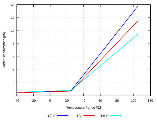
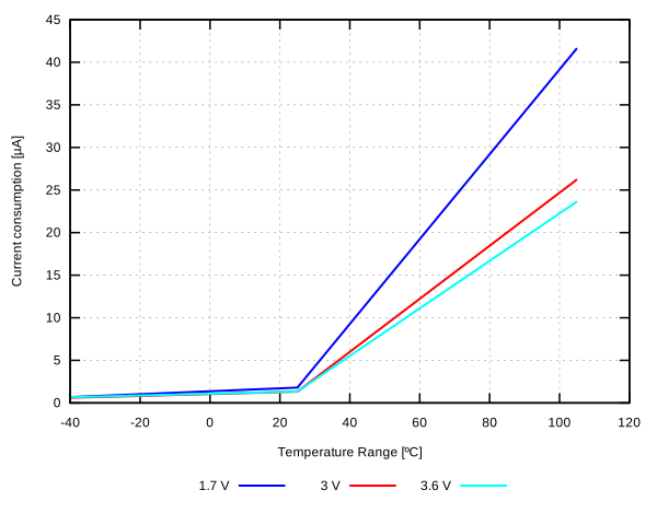
Sleep
| Symbol | Description | Min. | Typ. | Max. | Units |
|---|---|---|---|---|---|
| ION_IDLE1 | System ON, 0 kB application RAM, wake on any event | 1.3 | uA | ||
| ION_IDLE1,LDO | System ON, 0k application RAM, wake on any event, regulator = LDO | 3.3 | uA | ||
| ION_IDLE2 | System ON, wake on any event | 1.3 | uA | ||
| ION_IDLE2,LDO | System ON, wake on any event, regulator = LDO | 3.4 | uA | ||
| ION_IDLE3 | System ON, wake on any event, power-fail comparator enabled | 1.3 | uA | ||
| ION_IDLE3,128MHz | System ON, wake on any event, power-fail comparator enabled, clock=HFINT128M | 785 | uA | ||
| ION_IDLE4 | System ON, wake on GPIOTE input (event mode, LATENCY=LowLatency) | 48 | uA | ||
| ION_IDLE4_LP | System ON, wake on GPIOTE input (event mode, LATENCY=LowPower) | 1.3 | uA | ||
| ION_IDLE5 | System ON, wake on GPIOTE PORT event | 1.3 | uA | ||
| ION_IDLE6 | System ON, 0 kB application RAM, wake on RTC (running from LFXO clock) | 1.5 | uA | ||
| ION_IDLE7 | System ON, wake on RTC (running from LFXO clock) | 1.5 | uA | ||
| ION_IDLE8 | System ON, 0 kB application RAM, wake on RTC (running from LFXO clock), 5 V supply on VDDH, VREGH output = 3.3 V | 1.7 | uA | ||
| ION_IDLE7 | System ON, 0 kB network RAM, wake on network RTC (running from LFXO clock) | 1.5 | uA | ||
| ION_IDLE8 | System ON, 64 kB network RAM, wake on network RTC (running from LFXO clock) | 1.7 | uA | ||
| ION_IDLE9 | System ON, 0 kB application RAM, wake on RTC (running from LFRC clock) | 2.1 | uA | ||
| ION_IDLE10 | Both cores in System ON, wake on any event. VREQH=Disabled. | 1.3 | uA | ||
| ION_IDLE10_VREQH | Both cores in System ON, wake on any event. VREQH=Enabled. | 1.4 | uA | ||
| IOFF0 | System OFF, 0 kB application RAM, wake on reset | 1.0 | uA | ||
| IOFF0,LDO | System OFF, 0 kB application RAM, wake on reset; regulator = LDO | 1.4 | uA | ||
| IOFF1 | System OFF, 0 kB application RAM, wake on LPCOMP | 0.9 | uA | ||
| IOFF2 | System OFF, wake on reset | 0.9 | uA | ||
| IOFF3 | System OFF, 0 kB application RAM, wake on reset, 5 V supply on VDDH, VREGH output = 3.3V | 1.1 | uA | ||
| IOFF3,LDO | System OFF, 0 kB application RAM, wake on reset, 5 V supply on VDDH, VREGH output = 3.3V; regulator = LDO | 1.4 | uA | ||
| IOFF4 | System OFF, 512 kB application RAM + 64 kB network RAM, wake on reset | 2.4 | uA |
Application CPU running
The application CPU running parameters are obtained using the following compiler version:
Compiler: Arm version 6.14 (armclang)
-std=c99 --target=arm-arm-none-eabi -mcpu=cortex-m33 -mfpu=fpv5-sp-d16 -mfloat-abi=hard -fno-rtti -flto -funsigned-char -mcmse -Omax -ffunction-sections-Omax20 kB of RAM in application core switched on and retained in execute-from-flash cases, and 44 kB in execute-from-RAM cases.
| Symbol | Description | Min. | Typ. | Max. | Units |
|---|---|---|---|---|---|
| IAPPCPU0 | CPU running CoreMark from flash, regulator = LDO, clock = HFINT128M | 15.5 | mA | ||
| IAPPCPU2 | CPU running CoreMark from flash, clock = HFXO128M | 8.0 | mA | ||
| IAPPCPU3 | CPU running CoreMark from flash, clock = HFXO64M | 3.6 | mA | ||
| IAPPCPU4 | CPU running CoreMark from flash, clock = HFINT128M | 7.8 | mA | ||
| IAPPCPU5 | CPU running CoreMark from flash | 3.3 | mA | ||
| IAPPCPU8 | CPU running CoreMark from RAM, clock = HFINT128M | 7.9 | mA | ||
| IAPPCPU9 | CPU running CoreMark from RAM | 3.4 | mA | ||
| IAPPCPU10 | CPU running CoreMark from RAM, clock = HFXO128M | 8.2 | mA | ||
| IAPPCPU11 | CPU running CoreMark from RAM, clock = HFXO64M | 3.6 | mA |
Network CPU running
The network CPU running parameters are obtained using the following compiler version:
Compiler: Arm version 6.14 (armclang)
Compiler flags: -std=c99 --target=arm-arm-none-eabi -mcpu=cortex-m33+nodsp -mfpu=none -mfloat-abi=soft -fno-rtti -flto -funsigned-char -Omax -ffunction-sections-Omax20 kB of RAM in network core switched on and retained in execute-from-flash cases, and 40 kB in execute-from-RAM cases.
Clock and regulator settings only apply to network core. The settings in the application core are the same as the common conditions.
| Symbol | Description | Min. | Typ. | Max. | Units |
|---|---|---|---|---|---|
| INETCPU0 | CPU running CoreMark from flash, regulator = LDO | 5.1 | mA | ||
| INETCPU1 | CPU running CoreMark from flash | 2.4 | mA | ||
| INETCPU2 | CPU running CoreMark from flash, clock = HFXO64M | 2.6 | mA | ||
| INETCPU3 | CPU running CoreMark from RAM, regulator = LDO | 4.3 | mA | ||
| INETCPU4 | CPU running CoreMark from RAM | 2.0 | mA | ||
| INETCPU5 | CPU running CoreMark from RAM, clock = HFXO64M | 2.2 | mA |
COMP active
| Symbol | Description | Min. | Typ. | Max. | Units |
|---|---|---|---|---|---|
| ICOMP,LP | COMP enabled, Low-power mode | 60 | uA | ||
| ICOMP,NORM | COMP enabled, normal mode | 62 | uA | ||
| ICOMP,HS | COMP enabled, High-speed mode | 68 | uA |
I2S active
| Symbol | Description | Min. | Typ. | Max. | Units |
|---|---|---|---|---|---|
| II2S0 | I2S transferring data @ 2 x 16 bit x 16 kHz (CONFIG.MCKFREQ = 32MDIV63, CONFIG.RATIO = 32X), clock = HFXO64M | 2000 | uA | ||
| II2S1 | I2S transferring data @ 2 x 16 bit x 16 kHz (CONFIG.MCKFREQ = 510000, CONFIG.RATIO = 32X), clock = HFXO ACLK @ 12.288 MHz | 2170 | uA | ||
| II2S2 | I2S transferring data @ 2 x 16 bit x 48 kHz (CONFIG.MCKFREQ = 505286656, CONFIG.RATIO = 32X), clock = HFXO ACLK @ 12.288 MHz | 2310 | uA |
LPCOMP active
| Symbol | Description | Min. | Typ. | Max. | Units |
|---|---|---|---|---|---|
| ILPCOMP,EN | LPCOMP enabled | 45 | uA |
NFCT active
| Symbol | Description | Min. | Typ. | Max. | Units |
|---|---|---|---|---|---|
| ISENSE | System ON, current in SENSE STATE (this current does not apply when in NFC field) | 1.3 | uA | ||
| IACTIVATED | System ON, current in ACTIVATED STATE, clock = HFXO64M | 1080 | uA |
PDM active
| Symbol | Description | Min. | Typ. | Max. | Units |
|---|---|---|---|---|---|
| IPDM,RUN | PDM receiving and processing data @ 1 MHz (RATIO = 64, PDMCLKCTRL = 135274496), stereo mode, clock = HFXO64M | 655 | uA | ||
| IPDM,RUN,ACLK | PDM receiving and processing data @ 1 MHz (RATIO = 64, PDMCLKCTRL = 343597056), stereo mode, HFXO ACLK = 12.288 MHz | 1045 | uA |
PWM active
| Symbol | Description | Min. | Typ. | Max. | Units |
|---|---|---|---|---|---|
| IPWM,RUN0 | PWM running at 125 kHz, top = 10, duty = 50% | 560 | uA | ||
| IPWM,RUN1 | PWM running at 16 MHz, top = 10, duty = 50% | 560 | uA | ||
| IPWM,RUN1,LDO | PWM running at 16 MHz, top = 10, duty = 50%; regulator = LDO | 1035 | uA | ||
| IPWM,RUN2 | PWM running at 125 kHz, top = 10, duty = 50%, clock = HFXO64M | 750 | uA | ||
| IPWM,RUN3 | PWM running at 16 MHz, top = 10, duty = 50%, clock = HFXO64M | 755 | uA |
QDEC active
| Symbol | Description | Min. | Typ. | Max. | Units |
|---|---|---|---|---|---|
| IQDEC,RUN | QDEC running | 480 | uA |
QSPI active
| Symbol | Description | Min. | Typ. | Max. | Units |
|---|---|---|---|---|---|
| IQSPI,IDLE | QSPI idle (enabled, but not activated) | 45 | uA | ||
| IQSPI,ACTIVE | QSPI active (activated, but not transferring data) | 1790 | uA | ||
| IQSPI,DATA | QSPI transferring data (activated, and transferring data to/from external flash memory), SCKFREQ = 96 MHz, quad mode, clock = HFXO192M | 4430 | uA |
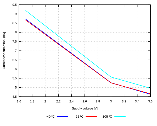
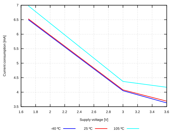
RADIO transmitting/receiving
64 kB of network core RAM switched on and retained.
Clock and regulator settings only apply to network core. The settings in the application core are the same as the common conditions.
| Symbol | Description | Min. | Typ. | Max. | Units |
|---|---|---|---|---|---|
| IRADIO_TX0 | Radio transmitting @ +3 dBm output power, 1 Mbps Bluetooth low energy (BLE) mode, clock = HFXO64M | 5.3 | mA | ||
| IRADIO_TX1 | Radio transmitting @ 0 dBm output power, 1 Mbps Bluetooth low energy (BLE) mode, clock = HFXO64M | 4.1 | mA | ||
| IRADIO_TX2 | Radio transmitting @ -40 dBm output power, 1 Mbps Bluetooth low energy (BLE) mode, clock = HFXO64M | 2.6 | mA | ||
| IRADIO_TX3 | Radio transmitting @ 0 dBm output power, 1 Mbps Bluetooth low energy (BLE) mode, clock = HFXO64M; regulator = LDO | 9.7 | mA | ||
| IRADIO_TX4 | Radio transmitting @ -40 dBm output power, 1 Mbps Bluetooth low energy (BLE) mode, clock = HFXO64M; regulator = LDO | 5.0 | mA | ||
| IRADIO_TX5 | Radio transmitting @ 0 dBm output power, 2 Mbps Bluetooth low energy (BLE) mode, clock = HFXO64M | 4.2 | mA | ||
| IRADIO_TX6 | Radio transmitting @ 0 dBm output power, 500 kbps Bluetooth low energy (BLE) long-range (LR) mode, clock = HFXO64M | 4.1 | mA | ||
| IRADIO_TX7 | Radio transmitting @ 0 dBm output power, 125 kbps Bluetooth low energy (BLE) long-range (LR) mode, clock = HFXO64M | 4.1 | mA | ||
| IRADIO_TX8 | Radio transmitting @ 0 dBm output power, 250 kbps IEEE 802.15.4-2006 mode, clock = HFXO64M | 4.1 | mA | ||
| IRADIO_RX0 | Radio receiving @ 1 Mbps Bluetooth low energy (BLE) mode, clock = HFXO64M | 3.7 | mA | ||
| IRADIO_RX1 | Radio receiving @ 1 Mbps Bluetooth low energy (BLE) mode, clock = HFXO64M; regulator = LDO | 8.0 | mA | ||
| IRADIO_RX2 | Radio receiving @ 2 Mbps Bluetooth low energy (BLE) mode, clock = HFXO64M | 4.1 | mA | ||
| IRADIO_RX3 | Radio receiving @ 500 kbps Bluetooth low energy (BLE) long-range (LR) mode, clock = HFXO64M | 3.6 | mA | ||
| IRADIO_RX4 | Radio receiving @ 125 kbps Bluetooth low energy (BLE) long-range (LR) mode, clock = HFXO64M | 3.6 | mA | ||
| IRADIO_RX5 | Radio receiving @ 250 kbps IEEE 802.15.4-2006 mode, clock = HFXO64M | 3.9 | mA |
RNG active
| Symbol | Description | Min. | Typ. | Max. | Units |
|---|---|---|---|---|---|
| IRNG0 | RNG running, 64 kB network RAM | 270 | uA |
SAADC active
| Symbol | Description | Min. | Typ. | Max. | Units |
|---|---|---|---|---|---|
| ISAADC,RUN | SAADC sampling @ 16 ksps, acquisition time = 20 us, clock = HFXO64M | 980 | uA | ||
| ISAADC,TASK | SAADC sampling @ 1 kHz from RTC in task mode, acquisition time = 20 us, clock = HFINT64M and LFXO | 160 | uA |
TEMP active
| Symbol | Description | Min. | Typ. | Max. | Units |
|---|---|---|---|---|---|
| ITEMP0 | TEMP started, 64 kB network RAM | 615 | uA |
TIMER running
| Symbol | Description | Min. | Typ. | Max. | Units |
|---|---|---|---|---|---|
| ITIMER0 | One TIMER running @ 1 MHz | 475 | uA | ||
| ITIMER1 | One TIMER running @ 1 MHz, clock = HFXO64M | 670 | uA | ||
| ITIMER2 | One TIMER running @ 16 MHz | 560 | uA | ||
| ITIMER2,LDO | One TIMER running @ 16 MHz; regulator = LDO | 1040 | uA | ||
| ITIMER3 | One TIMER running @ 16 MHz, clock = HFXO64M | 750 | uA | ||
| ITIMER3,LDO | One TIMER running @ 16 MHz, clock = HFXO64M; regulator = LDO | 1280 | uA | ||
| ITIMER4 | One TIMER running @ 16 MHz, clock = HFINT128M | 750 | uA | ||
| INET,TIMER0 | One network TIMER running @ 1 MHz | 170 | uA | ||
| INET,TIMER1 | One network TIMER running @ 1 MHz, clock = HFXO64M | 400 | uA | ||
| INET,TIMER2 | One network TIMER running @ 16 MHz | 220 | uA | ||
| INET,TIMER3 | One network TIMER running @ 16 MHz, clock = HFXO64M | 445 | uA |
SPIM active
| Symbol | Description | Min. | Typ. | Max. | Units |
|---|---|---|---|---|---|
| ISPIM0 | SPIM transferring data @ 2 Mbps | 935 | uA | ||
| ISPIM1 | SPIM transferring data @ 2 Mbps, clock = HFXO64M | 1145 | uA | ||
| ISPIM2 | SPIM transferring data @ 8 Mbps | 1705 | uA | ||
| ISPIM3 | SPIM transferring data @ 8 Mbps, clock = HFXO64M | 1930 | uA | ||
| ISPIM4 | SPIM transferring data @ 32 Mbps | 2115 | uA | ||
| ISPIM5 | SPIM transferring data @ 32 Mbps, clock = HFXO64M | 2345 | uA |
SPIS active
| Symbol | Description | Min. | Typ. | Max. | Units |
|---|---|---|---|---|---|
| ISPIS0 | SPIS configured and idle (enabled, no CSN activity) | 145 | uA | ||
| ISPIS1 | SPIS transferring data @ 2 Mbps | 713 | uA | ||
| ISPIS2 | SPIS transferring data @ 2 Mbps, clock = HFXO64M | 913 | uA |
TWIM active
| Symbol | Description | Min. | Typ. | Max. | Units |
|---|---|---|---|---|---|
| ITWIM0 | TWIM transferring data @ 100 kbps | 965 | uA | ||
| ITWIM1 | TWIM transferring data @ 100 kbps, clock = HFXO64M | 1170 | uA | ||
| ITWIM2 | TWIM transferring data @ 400 kbps | 1000 | uA | ||
| ITWIM3 | TWIM transferring data @ 400 kbps, clock = HFXO64M | 1205 | uA | ||
| ITWIM4 | TWIM transferring data @ 1000 kbps | 2050 | uA | ||
| ITWIM5 | TWIM transferring data @ 1000 kbps, clock = HFXO64M | 2295 | uA |
TWIS active
| Symbol | Description | Min. | Typ. | Max. | Units |
|---|---|---|---|---|---|
| ITWIS,IDLE | TWIS configured and enabled (IDLE state) | 45 | uA | ||
| ITWIS0 | TWIS transferring data @ 100 kbps | 945 | uA | ||
| ITWIS1 | TWIS transferring data @ 400 kbps | 985 | uA | ||
| ITWIS2 | TWIS transferring data @ 100 kbps, clock = HFXO64M | 1150 | uA | ||
| ITWIS3 | TWIS transferring data @ 400 kbps, clock = HFXO64M | 1185 | uA |
UARTE active
| Symbol | Description | Min. | Typ. | Max. | Units |
|---|---|---|---|---|---|
| IUARTE,IDLE0 | UARTE RX idle (started, waiting for data, no data transfer) | 645 | uA | ||
| IUARTE,IDLE1 | UARTE RX idle (started, waiting for data, no data transfer), clock = HFXO64M | 840 | uA | ||
| IUARTE0 | UARTE transferring data @ 1200 bps, clock = HFXO64M | 885 | uA | ||
| IUARTE1 | UARTE transferring data @ 115200 bps, clock = HFXO64M | 890 | uA | ||
| IUARTE2 | UARTE receiving data @ 115200 bps, clock = HFXO64M | 890 | uA | ||
| IUARTE3 | UARTE transmitting and receiving data @ 115200 bps, clock = HFXO64M | 895 | uA |
WDT active
| Symbol | Description | Min. | Typ. | Max. | Units |
|---|---|---|---|---|---|
| IWDT,APP | Application MCU WDT started | 2.0 | uA | ||
| IWDT,APP,LDO | Application MCU WDT started; regulator = LDO | 4.9 | uA | ||
| IWDT,NET | Network MCU WDT started, 64 kB network RAM | 3.2 | uA |
Compounded
These are scenarios where both cores are active. 20 kB of RAM in the application core and 64 kB of RAM in the network core are switched on and retained.
In scenarios where both cores are active, the clock and regulator settings apply to both.
| Symbol | Description | Min. | Typ. | Max. | Units |
|---|---|---|---|---|---|
| IS0 | Application CPU running CoreMark from flash, radio transmitting @ 0 dBm output power, 1 Mbps Bluetooth Low Energy mode; clock = HFXO64M | 7.3 | mA | ||
| IS1 | Application CPU running CoreMark from flash, radio receiving @ 1 Mbps Bluetooth Low Energy mode; clock = HFXO64M | 6.9 | mA | ||
| IS2 | Application CPU running CoreMark from flash, radio transmitting @ 0 dBm output power, 1 Mbps Bluetooth Low Energy mode; clock = HFXO64M, regulator = LDO | 16.9 | mA | ||
| IS3 | Application CPU running CoreMark from flash, radio receiving @ 1 Mbps Bluetooth Low Energy mode; clock = HFXO64M; regulator = LDO | 15.6 | mA | ||
| IS4 | Application CPU running CoreMark from flash, radio transmitting @ 0 dBm output power, 1 Mbps Bluetooth Low Energy mode; clock = HFXO64M, 5 V supply on VDDH, VREGH output = 3.3 V | 6.7 | mA | ||
| IS5 | Application CPU running CoreMark from flash, radio receiving @ 1 Mbps Bluetooth Low Energy mode; clock = HFXO64M, 5 V supply on VDDH, VREGH output = 3.3 V | 6.4 | mA | ||
| IS6 | Network CPU running CoreMark from flash, radio transmitting @ 0 dBm output power, 1 Mbps Bluetooth Low Energy mode, clock = HFXO64M | 5.9 | mA | ||
| IS7 | Network CPU running CoreMark from flash, radio receiving @ 1 Mbps Bluetooth Low Energy mode, clock = HFXO64M | 5.4 | mA | ||
| IS8 | Application + Network CPU running CoreMark from flash, radio transmitting @ 0 dBm output power, 1 Mbps Bluetooth Low Energy mode; clock = HFXO64M | 9.1 | mA | ||
| IS9 | Application + Network CPU running CoreMark from flash, radio receiving @ 1 Mbps Bluetooth Low Energy mode; clock = HFXO64M | 8.6 | mA | ||
| IS10 | Application + Network CPU running CoreMark from flash, radio transmitting @ +3 dBm output power, 1 Mbps Bluetooth Low Energy mode; clock = HFXO64M | 9.9 | mA | ||
| IS11 | Application + Network CPU running CoreMark from flash, radio transmitting @ +3 dBm output power, 1 Mbps Bluetooth Low Energy mode; clock = HFXO64M; regulator = LDO | 21.5 | mA | ||
| IS12 | Application + Network CPU running CoreMark from flash, radio transmitting @ 0 dBm output power, 1 Mbps Bluetooth Low Energy mode; clock = HFXO64M; regulator = LDO | 20.2 | mA | ||
| IS13 | Application + Network CPU running CoreMark from flash, radio receiving @ 1 Mbps Bluetooth Low Energy mode; clock = HFXO64M; regulator = LDO | 21.5 | mA | ||
| IS14 | Network CPU running CoreMark from flash, radio transmitting @ 0 dBm output power, 1 Mbps Bluetooth Low Energy mode, clock = HFXO64M; regulator = LDO | 12.6 | mA | ||
| IS15 | Network CPU running CoreMark from flash, radio receiving @ 1 Mbps Bluetooth Low Energy mode, clock = HFXO64M; regulator = LDO | 14.0 | mA |
USBD active
| Symbol | Description | Min. | Typ. | Max. | Units |
|---|---|---|---|---|---|
| IUSB,ACTIVE,VBUS | Current from VBUS supply, USB active | 1.2 | mA | ||
| IUSB,SUSPEND,VBUS | Current from VBUS supply, USB suspended, CPU sleeping | 180 | uA | ||
| IUSB,ACTIVE,VDD | Current from VDD supply (normal voltage mode), all RAM retained, CPU running, USB active | 3.0 | mA | ||
| IUSB,SUSPEND,VDD | Current from VDD supply (normal voltage mode), all RAM retained, CPU sleeping, USB suspended | 815 | uA | ||
| IUSB,SUSPEND,VDD,LDO | Current from VDD supply (normal voltage mode), all RAM retained, CPU sleeping, USB suspended, regulator = LDO | 135 | uA | ||
| IUSB,ACTIVE,VDDH | Current from VDDH supply (high voltage mode), VDD=3 V (VREGH output), all RAM retained, CPU running, USB active | 3.2 | mA | ||
| IUSB,SUSPEND,VDDH | Current from VDDH supply (high voltage mode), VDD=3 V (VREGH output), all RAM retained, CPU sleeping, USB suspended | 2340 | uA | ||
| IUSB,SUSPEND,VDDH,LDO | Current from VDDH supply (high voltage mode), VDD=3 V (VREGH output), all RAM retained, CPU sleeping, USB suspended, regulator = LDO | 125 | uA | ||
| IUSB,DISABLED,VDD | Current from VDD supply, USB disabled, VBUS supply connected, all RAM retained, CPU sleeping | 3 | uA |