TWIM Electrical specification
TWIM interface electrical specifications
| Symbol | Description | Min. | Typ. | Max. | Units |
|---|---|---|---|---|---|
| fTWIM,SCL | Bit rates for TWIM1 | 100 | 1000 | kbps | |
| tTWIM,START | Time from STARTRX/STARTTX task to transmission started | 1.5 | µs |
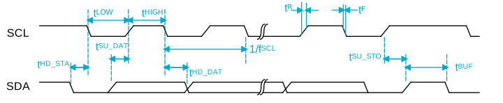
Two Wire Interface Master (TWIM) timing specifications
| Symbol | Description | Min. | Typ. | Max. | Units |
|---|---|---|---|---|---|
| tTWIM,SU_DATI | Input data setup time before positive edge on SCL – all modes | 20 | ns | ||
| tTWIM,HD_DATO | Output data hold time after negative edge on SCL – 100, 250 and 400 kbps | 500 | 625 | ns | |
| tTWIM,HD_STA,100kbps | TWIM master hold time for START and repeated START condition, 100 kbps | 10000 | ns | ||
| tTWIM,HD_STA,250kbps | TWIM master hold time for START and repeated START condition, 250 kbps | 4000 | ns | ||
| tTWIM,HD_STA,400kbps | TWIM master hold time for START and repeated START condition, 400 kbps | 2400 | ns | ||
| tTWIM,SU_STO,100kbps | TWIM master setup time from SCL high to STOP condition, 100 kbps | 5000 | ns | ||
| tTWIM,SU_STO,250kbps | TWIM master setup time from SCL high to STOP condition, 250 kbps | 2000 | ns | ||
| tTWIM,SU_STO,400kbps | TWIM master setup time from SCL high to STOP condition, 400 kbps | 1250 | ns | ||
| tR,100kbps | Rise time of both SDA and SCL signals, 100kbps | 1000 | ns | ||
| tF,100kbps | Fall time of both SDA and SCL signals, 100kbps | 300 | ns | ||
| tR,400kbps | Rise time of both SDA and SCL signals, 400kbps | 300 | ns | ||
| tF,400kbps | Fall time of both SDA and SCL signals, 400kbps | 300 | ns | ||
| tTWIM,BUF,100kbps | TWIM master bus free time between STOP and START conditions, 100 kbps | 5200 | ns | ||
| tTWIM,BUF,250kbps | TWIM master bus free time between STOP and START conditions, 250 kbps | 2200 | ns | ||
| tTWIM,BUF,400kbps | TWIM master bus free time between STOP and START conditions, 400 kbps | 1500 | ns |