Peripheral interface
Peripherals are controlled by the CPU through configuration, task, and event registers. Task registers are inputs, enabling the CPU and other peripherals to initiate a functionality. Event registers are outputs, enabling a peripheral to trigger tasks in other peripherals or the CPU by tying events to CPU interrupts.
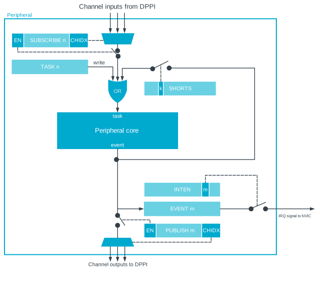
The distributed programmable peripheral interconnect (DPPI) feature enables peripherals to connect events to tasks without CPU intervention. For more information on DPPI and the DPPI channels, see DPPI — Distributed programmable peripheral interconnect.
Peripheral ID
Each peripheral is assigned a fixed block of address space that is minimum 4 KB in size and has at least 1024 registers of 32 bits.
For more information on available peripherals and their location in the address map, see Instantiation.
base_address = 0x40000000 + 0x1000 * ID- 0x40000000 is assigned ID=0
- 0x40001000 is assigned ID=1
- 0x4001F000 is assigned ID=31
Peripherals can share the same ID, which has the following limitations:
- Shared registers or common resources
- Limited availability due to mutually exclusive operation; only one peripheral in use at a time
- Enforced peripheral behavior when switching between peripherals (disable the first peripheral before enabling the second)
Peripherals with shared ID
Peripherals sharing ID [1...n] and a base address may not be used simultaneously. Only one peripheral can be enabled at a given ID.
When switching between two peripherals sharing an ID, perform the following to prevent unwanted behavior.
- Disable the previously used peripheral.
- Disable any publish/subscribe connection to the DPPI system for the peripheral that is being disabled.
- Clear all bits in the INTEN register (INTENCLR = 0xFFFFFFFF).
- Configure the peripheral being enabled. Do not rely on the inherited configuration from the disabled peripheral.
- Enable the peripheral.
For a list of peripherals that share an ID, see Instantiation.
Peripheral registers
Most peripherals have an ENABLE register. Unless otherwise specified, the peripheral registers must be configured before enabling the peripheral.
PSEL registers must be set before a peripheral is enabled or started. Updating PSEL registers while the peripheral is running can cause undefined behavior. To connect a peripheral to a different GPIO, the following must be performed:
- Disable the peripheral.
- Update the PSEL register.
- Re-enable the peripheral.
Most of the register values are not retained during System OFF or when a reset is triggered. Some registers will retain their values in System OFF or for some specific reset sources. These registers are marked as retained in the register description for a given peripheral. For more information on their behavior, see chapter RESET — Reset control.
Bit set and clear
Registers with multiple single-bit fields can implement the set-and-clear bit pattern. This bit pattern enables firmware to set and clear individual bits in a register without having to perform a read-modify-write operation to the main register.
This bit pattern is implemented using three consecutive addresses in the register map, where the main register is followed by dedicated SET and CLR registers (in that exact order).
In the main register, the SET register sets individual bits and the CLR register clears them. Writing 1 to a bit in the SET or CLR register will set or clear the same bit in the main register. Writing 0 to a bit in the SET or CLR register has no effect. Reading the SET or CLR register returns the value of the main register.
Tasks
Tasks trigger actions in a peripheral, such as to start a particular behavior. A peripheral can implement multiple tasks, with each task having a separate register in that peripheral's task register group.
A task is triggered when firmware writes 1 to the task register, or when the peripheral itself or another peripheral toggles the corresponding task signal. See the figure Peripheral interface.
Events
Events notify peripherals and the CPU about events that have happened, such as a state change in a peripheral. A peripheral may generate multiple events, where each event has a separate register in that peripheral's event register group.
An event is generated when the peripheral toggles the corresponding event signal and updates the event register to show an event has been generated, see figure Peripheral interface. An event register is cleared when firmware writes a 0 to that register. A peripheral can continually generate events when the event register is 1.
Publish and subscribe
Events and tasks from different peripherals can be connected together through the DPPI system using the PUBLISH and SUBSCRIBE registers in each peripheral. See Peripheral interface.
An event can be published onto a DPPI channel by configuring the event's PUBLISH register. Similarly, a task can subscribe to a DPPI channel by configuring the task's SUBSCRIBE register.
See DPPI — Distributed programmable peripheral interconnect for details.
Shortcuts
A shortcut is a direct connection between an event and a task within the same peripheral. If a shortcut is enabled, the associated task is automatically triggered when its associated event is generated.
Using shortcuts is the same as connecting a task and event outside the peripheral through the DPPI. The propagation delay for a shortcut is usually shorter than the propagation delay through the DPPI.
Shortcuts are predefined, which means that their connections cannot be configured by firmware. Each shortcut can be individually enabled or disabled through the shortcut register, one bit per shortcut, giving a maximum of 32 shortcuts for each peripheral.
Interrupts
All peripherals support interrupts generated by events.
Events generated by a peripheral can be configured to generate interrupts using registers INTEN, INTENSET, and INTENCLR. Multiple events can be enabled to generate interrupts simultaneously. Event registers in the peripheral register event group indicate the source.
Some peripherals implement only INTENSET and INTENCLR registers. The INTEN register is not available on those peripherals. See the individual peripheral chapters for details. In all cases, reading back the INTENSET or INTENCLR register returns the same information as INTEN.
The INTPEND register contains the interrupt pending status of events generated by a peripheral. This is a read-only register. To clear bits from INTPEND, clear the corresponding event register.
Each event implemented in the peripheral is associated with a specific bit position in the INTEN, INTENSET, and INTENCLR registers.
- Clear the pending interrupt by writing 0 to the corresponding EVENT register
- Disable the interrupt by using the INTEN or INTENCLR registers
The relationship between tasks, events, shortcuts, and interrupts is illustrated in Peripheral interface.
A peripheral can occupy single or multiple interrupts. For single interrupts, the interrupt number follows the peripheral ID. For example, the peripheral with ID=4 is connected to interrupt number 4 in the nested vectored interrupt controller (NVIC). In this case, only single INTEN registers are available.
Peripherals implementing multiple interrupts have several INTEN registers that follow the convention of INTENn, where n is the interrupt number from the peripheral. This also applies to corresponding INTPEND, INTENSET, and INTENCLR registers. This feature enables any event to generate an interrupt from the peripheral.
Peripherals implementing more than 32 events have access to multiple INTEN registers that follow the convention of INTENn, where n is the event group number. The 32 lowest events in the peripheral make event group 0. The next 32 events in the peripheral make event group 1, and so on. This convention is also applicable for corresponding INTPEND, INTENSET, and INTENCLR registers.
Peripherals implementing both multiple interrupts and more than 32 events have multiple INTEN registers. In this case, registers follow the convention of INTENnm, where n is interrupt number from the peripheral and m is event group number. This convention is also applicable for corresponding INTPEND, INTENSET, and INTENCLR registers.
Interrupt clearing and disabling
Interrupts must be cleared by writing 0 to the corresponding EVENT register.
Interrupts are immediately re-triggered until cleared. Routines for software interrupt services continue to execute, even if a new event has not been received.