RADIO — 2.4 GHz radio
The 2.4 GHz radio transceiver is compatible with multiple radio standards such as Bluetooth® Low Energy, IEEE 802.15.4, and Nordic's proprietary protocols.
The main features of the RADIO peripheral are the following:
- Multidomain 2.4 GHz radio transceiver, with
- Bluetooth Low Energy 1 Mbps and 2 Mbps modes
- Bluetooth Low Energy Long Range (125 kbps and 500 kbps) modes
- IEEE 802.15.4 250 kbps mode
- 1 Mbps, 2 Mbps and 4 Mbps Nordic proprietary modes
- Efficient data interface with EasyDMA support
- Automatic address filtering and pattern matching
- Automated packet assembler/disassembler
- Automated CRC generator and checker
EasyDMA, in combination with an automated packet assembler, packet disassembler, automated CRC generator and CRC checker, makes it easy to configure and use RADIO. See the following figure for details.
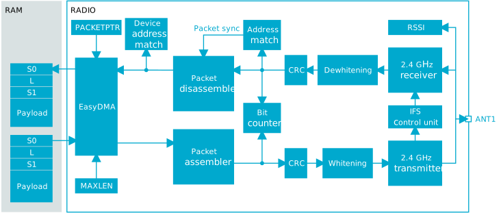
RADIO includes a device address match unit and an interframe spacing control unit that can be utilized to simplify device filtering and interframe spacing respectively in Bluetooth Low Energy and similar applications.
RADIO also includes a received signal strength indicator (RSSI) and a bit counter. The bit counter generates events when a preconfigured number of bits are sent or received by RADIO.
Packet configuration
A RADIO packet contains the fields PREAMBLE, ADDRESS, S0, LENGTH, S1, PAYLOAD, and CRC. For Long Range (125 kbps and 500 kbps) Bluetooth Low Energy modes, fields CI, TERM1, and TERM2 are also included.
The content of a RADIO packet is illustrated in the following figures. RADIO sends the fields in the packet according to the sequence shown in the figures, starting on the left.


PREAMBLE is sent with least significant bit first on air. The size of the PREAMBLE depends on the mode selected in the MODE register, and is configured using PCNF0.PLEN.
| Preamble | |||
|---|---|---|---|
| MODE | Preamble size (octets) | When first bit of ADDRESS is 0 | When first bit of ADDRESS is 1 |
| Ble_1Mbit | 1 | 0xAA | 0x55 |
| Nrf_1Mbit | 1 | 0xAA | 0x55 |
| Nrf_2Mbit | 1 | 0xAA | 0x55 |
| Ble_2Mbit | 2 | 0xAAAA | 0x5555 |
| Nrf_4Mbit_0BT4 | 2 | 0xAAAA | 0x5555 |
| Nrf_4Mbit_0BT6 | 2 | 0xAAAA | 0x5555 |
| Ble_LR125Kbit | Any | 10 repetitions of 0x3C | |
| Ble_LR500Kbit | Any | 10 repetitions of 0x3C | |
| Ieee802154_250Kbit | Any | 4 repetitions of 0x00 | |
Radio packets are stored in memory inside instances of a RADIO packet data structure as shown in the following figure. The PREAMBLE, ADDRESS, CI, TERM1, TERM2, and CRC fields are omitted in this data structure. Fields S0, LENGTH, and S1 are optional.

The byte ordering on air is always least significant byte first for the ADDRESS and PAYLOAD fields, and most significant byte first for the CRC field. The ADDRESS fields are always transmitted and received least significant bit first. The CRC field is always transmitted and received most significant bit first. The endianness, meaning the order in which the bits are sent and received, of the S0, LENGTH, S1, and PAYLOAD fields can be configured via PCNF1.ENDIAN.
The sizes of the S0, LENGTH, and S1 fields can be individually configured via S0LEN, LFLEN, and S1LEN in PCNF0, respectively. If any of these fields are configured to be less than 8 bits, the least significant bits of the fields are used.
If S0, LENGTH, or S1 are specified with zero length, their fields will be omitted in memory. Otherwise, each field will be represented as a separate byte, regardless of the number of bits in their on-air counterpart.
Independent of the configuration of PCNF1.MAXLEN, the combined length of S0, LENGTH, S1, and PAYLOAD cannot exceed 258 bytes.
Address configuration
The on-air radio ADDRESS field is composed of two parts, the base address field and the address prefix field.
The size of the base address field is configurable via the PCNF1.BALEN register. The base address is truncated from the least significant byte if PCNF1.BALEN is less than 4. See Definition of logical addresses.
The on-air addresses are defined in the BASE0/BASE1 registers and PREFIX0/PREFIX1 registers. It is only when writing these registers that the user must relate to the actual on-air addresses. For other radio address registers, such as the TXADDRESS, RXADDRESSES, and RXMATCH registers, logical radio addresses ranging from 0 to 7 are used. The relationship between the on-air radio addresses and the logical addresses is described in the following table.
| Logical address | Base address | Prefix byte |
|---|---|---|
| 0 | BASE0 | PREFIX0.AP0 |
| 1 | BASE1 | PREFIX0.AP1 |
| 2 | BASE1 | PREFIX0.AP2 |
| 3 | BASE1 | PREFIX0.AP3 |
| 4 | BASE1 | PREFIX1.AP4 |
| 5 | BASE1 | PREFIX1.AP5 |
| 6 | BASE1 | PREFIX1.AP6 |
| 7 | BASE1 | PREFIX1.AP7 |
Data whitening
Packet whitening and de-whitening is possible with RADIO and is enabled in PCNF1.WHITEEN. When enabled, whitening and de-whitening will be handled by RADIO automatically as packets are sent and received.
The data whitening is done by means of a configurable linear feedback shift register in a one-to-many topology, as illustrated in the following figure. Bit 0 is used to exclusive OR (XOR) the data packet that is to be whitened or de-whitened. The linear feedback shift register is configured and initialized using the DATAWHITE register. The reset value for the DATAWHITE.POLY field is compatible with Bluetooth Low Energy. The initial vector is configured in DATAWHITE.IV.
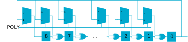
Whitening and de-whitening will be performed over the whole packet except for the preamble and the address fields.
Including the address field in CRC check (CRCCNF.SKIPADDR = Include) is not supported for whitened packets.
CRC
The cyclic redundancy check (CRC) generator in RADIO calculates the CRC over the whole packet excluding the preamble.
The device also supports excluding the address field from the CRC calculation, see the CRCCNF.SKIPADDR register for more information.
The CRC polynomial is configurable as illustrated in the following figure, where bit 0 in the register CRCPOLY corresponds to X0 and bit n corresponds to Xn. See CRCPOLY for more information.
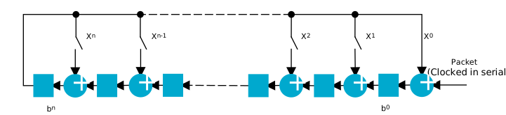
The figure shows that the CRC is calculated by feeding the packet serially through the CRC generator. Before the packet is clocked through the CRC generator, the CRC generator's latches b[0..n] will be initialized with a predefined value specified in the register CRCINIT. After the whole packet has been clocked through the CRC generator, b[0..n] will hold the resulting CRC. This value will be used by RADIO during both transmission and reception. The CPU cannont read latches b[0..n] at any time. However, a received CRC can be read by the CPU via the register RXCRC.
The length (n) of the CRC is configurable, see CRCCNF for more information.
When the entire packet including the CRC has been received, and no errors were detected, RADIO generates the event CRCOK. If CRC errors were detected, the event CRCERROR is generated.
The CRC check status can be read from the register CRCSTATUS after a packet has been received.
Radio states
Tasks and events are used to control the operating state of RADIO when in RX mode or TX mode.
| State | Description |
|---|---|
| DISABLED | No operations are going on inside RADIO and the power consumption is at a minimum |
| RXRU | RADIO is ramping up and preparing for reception |
| RXIDLE | RADIO is ready for reception to start |
| RX | Reception has been started and the addresses enabled in the RXADDRESSES register are being monitored |
| RXDISABLE | RADIO is disabling the receiver |
| SETTLE | RADIO is waiting for the PLL to settle |
| PLL | The PLL has settled |
| TXRU | RADIO is ramping up and preparing for transmission |
| TXIDLE | RADIO is ready for transmission to start |
| TX | RADIO is transmitting a packet |
| TXDISABLE | RADIO is disabling the transmitter |
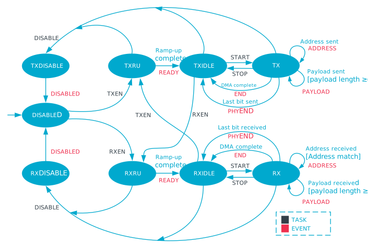
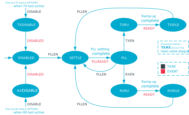
This figure shows how the tasks and events relate to the RADIO peripheral's operation. RADIO does not prevent a task from being triggered from the wrong state. For example, if the RXEN task is triggered from the RXDISABLE state, this may lead to unpredictable behavior. The PAYLOAD event is always generated, even if the payload is zero.
The END to START shortcut should not be used with IEEE 802.15.4 250 kbps mode. Use the PHYEND to START shortcut instead.
The END to START shortcut should not be used with Long Range (125 kbps and 500 kbps) Bluetooth Low Energy modes. Use the PHYEND to START shortcut instead.
Transmit sequence
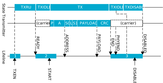
Before RADIO can transmit a packet, it must first ramp-up in TX mode. See TXRU in Radio states without PLL and Transmit sequence. A TXRU ramp-up sequence is initiated when the TXEN task is triggered. After RADIO has successfully ramped up, it will generate the READY event indicating that a packet transmission can be initiated. A packet transmission is initiated by triggering the START task. The START task can first be triggered after RADIO has entered into the TXIDLE state.
The following figure illustrates a single packet transmission where the CPU manually triggers the different tasks needed to control the flow of RADIO, meaning no shortcuts are used. If shortcuts are not used, a certain amount of delay caused by CPU execution is expected between READY and START, and between PHYEND and DISABLE. As illustrated in the following figure, RADIO will by default transmit an unmodulated carrier between READY and START, and between PHYEND and DISABLED.
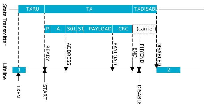
The following figure shows a transmit sequence where no delay is introduced. RADIO is configured to use shortcuts between READY and START, and between PHYEND and DISABLE.
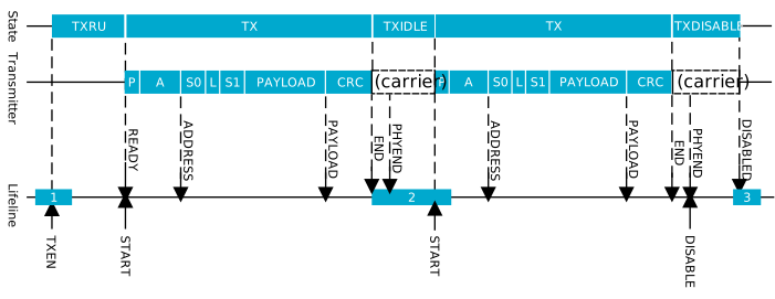
RADIO is able to send multiple packets one after the other without having to disable and re-enable RADIO between packets, as illustrated in the following figure.
Receive sequence
Before RADIO is able to receive a packet, it must first ramp up in RX mode. See RXRU in Radio states without PLL and Receive sequence for more information.
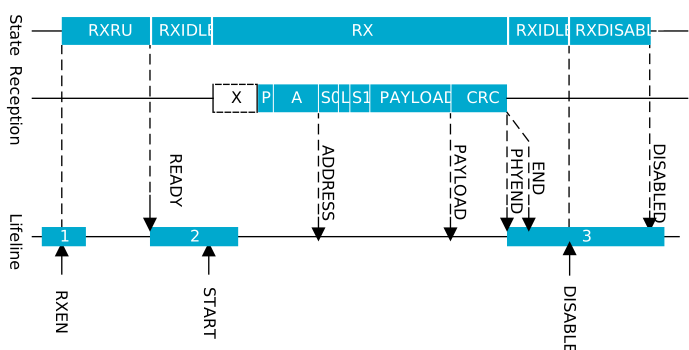
An RXRU ramp-up sequence is initiated when the RXEN task is triggered. After RADIO has successfully ramped up, it will generate the READY event indicating that a packet reception can be initiated. A packet reception is initiated by triggering the START task. As illustrated in Radio states without PLL, the START task can first be triggered after RADIO has entered the RXIDLE state.
The following figure shows a single packet reception where the CPU manually triggers the tasks needed to control the flow of RADIO, meaning no shortcuts are used. If shortcuts are not used, a certain amount of delay caused by CPU execution is expected between READY and START, and between PHYEND and DISABLE. RADIO will be listening and possibly receiving undefined data, represented with an X, from START and until a packet with valid preamble (P) is received.
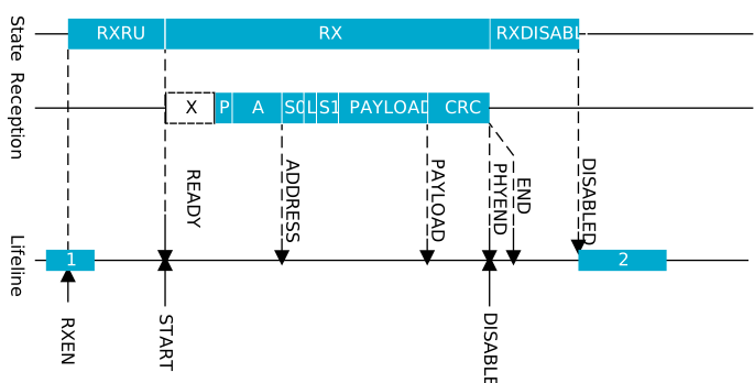
The following figure shows a receive sequence where no delay is introduced. RADIO is configured to use shortcuts between READY and START, and between PHYEND and DISABLE.
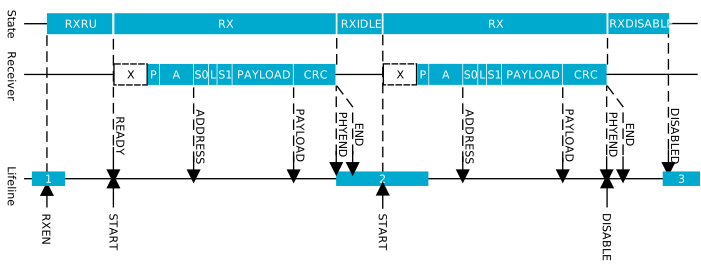
RADIO can receive consecutive packets without having to disable and re-enable RADIO between packets, as illustrated in the following figure.
Received signal strength indicator (RSSI)
RADIO implements a mechanism for measuring the power in the received signal. This feature is called received signal strength indicator (RSSI).
The RSSI is continuously measured and the value filtered using a single-pole IIR filter. After a signal level change, the RSSI will settle after approximately RSSISETTLE.
Sampling the received signal strength is started by using the RSSISTART task. The sample can be read from the RSSISAMPLE register.
The sample period of the RSSI is defined by RSSIPERIOD. The RSSISAMPLE will hold the filtered received signal strength after this sample period.
For the RSSI sample to be valid, RADIO has to be enabled in RX mode by triggering the RXEN task and the reception has to be started with the READY event followed by START task.
Interframe spacing (IFS)
Interframe spacing (IFS) is defined as the time in microseconds between two consecutive packets, starting from when the end of the last bit of the previous packet is received, to the beginning of the first bit of the subsequent packet that is transmitted.
RADIO can enforce this interval, as specified in the TIFS register, as long as the TIFS register is not specified to be shorter than the RADIO peripheral's turnaround time (meaning the time needed to switch off the receiver and then switch on the transmitter). The TIFS register can be written any time before the last bit on air is received.
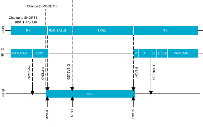
TIFS is only enforced if the shortcuts PHYEND to DISABLE and DISABLED to TXEN or PHYEND to DISABLE and DISABLED to RXEN are enabled. The short READY to START must also be enabled. In these configurations, TXEN or RXEN is automatically delayed to achieve the configured interframe spacing.
TIFS is qualified for use in IEEE 802.15.4 250kbps mode, Bluetooth Low Energy Long Range (125 kbps and 500 kbps) modes, and Bluetooth Low Energy 1 Mbps and 2 Mbps modes, using the Legacy ramp-up mode.
SHORTS and TIFS registers are not double-buffered and can be updated at any point before the last bit on air is received.
Device address match
The device address match feature is tailored for device filtering in Bluetooth Low Energy and similar implementations.
This feature enables on-the-fly device address matching while receiving a packet over-the-air. This feature only works in RX mode and when RADIO is configured for little endian, see PCNF1.ENDIAN for more information.
The device address match unit assumes that the first 48 bits of the payload are the device address and that bit number 6 in S0 is the TxAdd bit. See the Bluetooth Core Specification for more information about device addresses, TxAdd, and the device filtering procedure.
RADIO is able to listen for eight different device addresses at the same time. These addresses are specified in a DAB/DAP register pair, one pair per address, in addition to a TxAdd bit configured in the DACNF register. The DAB register specifies the 32 least significant bits of the device address, while the DAP register specifies the 16 most significant bits of the device address.
Each of the device addresses can be individually included or excluded from the matching mechanism. This is configured in the DACNF register.
Bit counter
RADIO implements a simple counter that can be configured to generate an event after a specific number of bits has been transmitted or received.
By using shortcuts, this counter can be started from different events generated by RADIO and count relative to these events.
The bit counter is started by triggering the BCSTART task, and stopped by triggering the BCSTOP task. A BCMATCH event will be generated when the bit counter has counted the bits specified in register BCC. The bit counter will continue to count bits until the DISABLED event is generated or until the BCSTOP task is triggered. After the BCMATCH event, the CPU can reconfigure the value BCC for new BCMATCH events within the same packet.
The bit counter can only be started after RADIO has received the ADDRESS event.
The bit counter will stop and reset for the tasks BCSTOP, STOP, or DISABLE, or the event END.
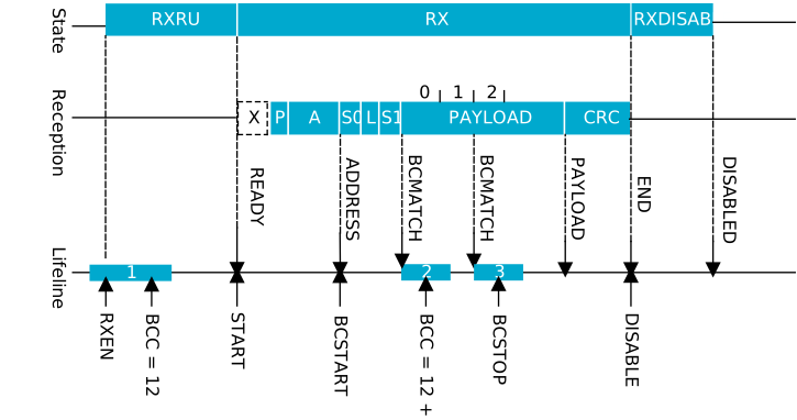
The following figure shows how the bit counter can be used to generate the BCMATCH event in the beginning of the packet payload, and again generate a second BCMATCH event after sending 2 bytes (16 bits) of the payload.
IEEE 802.15.4 operation
The IEEE standard 802.15.4 differs from the Nordic proprietary and Bluetooth Low Energy modes. Differences include modulation scheme, channel structure, packet structure, security, and medium access control.
- Ultra-low power 250 kbps, 2450 MHz, IEEE 802.15.4-2020 compliant link
- Clear channel assessment (CCA)
- Energy detection (ED) scan
- CRC generation
To enable RADIO to comply with the IEEE 802.15.4-2020 standard, set MODE = Ieee802154_250kbit.
Packet structure
IEEE 802.15.4 defines an on-the-air frame/packet that is different from what is used in Bluetooth Low Energy.
The following figure provides an overview of the physical frame structure and its timing.
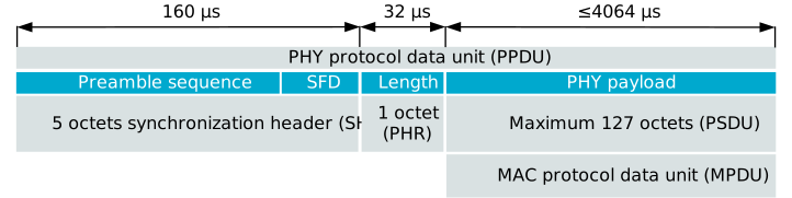
The standard uses the term octet for an 8-bit storage unit within the PPDU. For timing, the value symbol is used, and it has a duration of 16 µs.
The total usable payload (PSDU) is 127 octets, but when CRC is in use, this is reduced to 125 octets of usable payload.
The preamble sequence consists of four octets that are all 0 and are used for synchronizing the RADIO peripheral's receiver. Following the preamble is the single octet start of frame delimiter (SFD), with a fixed value of 0xA7. An alternate SFD can be programmed through the SFD register, providing an initial level of frame filtering when non-standard compliance is chosen. It is a valuable feature when operating in a congested or private network. The preamble sequence and the SFD are generated by RADIO and are not programmed by the user into the frame buffer.
Following the five octet synchronization header (SHR) is the single octet PHY header (PHR). The least significant seven bits of PHR denote the frame length of the following PSDU. The most significant bit is reserved and is set to 0 for frames that are standard compliant. RADIO reports all eight bits which can be used to carry additional information. The PHR is the first byte written to the frame data memory pointed to by PACKETPTR. Frames with zero length are discarded, and the FRAMESTART event is not generated in this case.
The next N octets carry the data of the PHY packet, where N equals the value of the PHR. For an implementation also using the IEEE 802.15.4 medium access control (MAC) layer, the PHY data is a MAC frame of N-2 octets, because two octets occupy a CRC field.
- A header, which is composed of the following:
- The frame control field (FCF)
- The sequence number
- Addressing fields
- A payload
- The 16-bit frame control sequence (FCS)
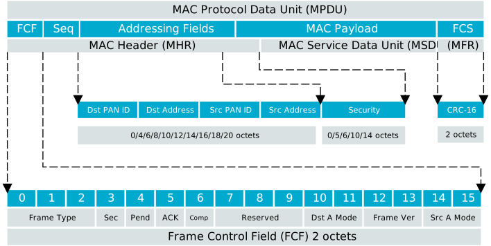
The two FCF octets contain information about the frame type, addressing, and other control flags. This field is decoded when using the assisted operating modes offered by RADIO.
The sequence number is a single octet in size and is unique for a frame. It is used in the associated acknowledgement frame sent upon successful frame reception.
The addressing field can be zero (acknowledgement frame) or up to 20 octets in size. The field is used to direct packets to the correct recipient and denote its origin. IEEE 802.15.4 bases its addressing on networks being organized in PANs with 16-bit identifier and nodes having a 16-bit or 64-bit address. In the assisted receive mode, these parameters are analyzed for address matching and acknowledgement.
The MAC payload carries the data of the next higher layer, or in the case of a MAC command frame, information used by the MAC layer itself.
The two last octets contain the 16-bit ITU-T CRC. The FCS is calculated over the MAC header (MHR) and MAC payload (MSDU) parts of the frame. This field is calculated automatically when sending a frame, or indicated in the CRCSTATUS register when a frame is received. If configured, this feature is maintained autonomously by the CRC module.
Operating frequencies
IEEE 802.15.4 defines 16 channels in the 2450 MHz frequency band. The channels are numbered from 11 to 26, each with a width of 5 MHz.
To choose the correct channel center frequency, the FREQUENCY register must be programmed according to the following table.
| IEEE 802.15.4 channel | Center frequency (MHz) | FREQUENCY setting |
|---|---|---|
| Channel 11 | 2405 | 5 |
| Channel 12 | 2410 | 10 |
| Channel 13 | 2415 | 15 |
| Channel 14 | 2420 | 20 |
| Channel 15 | 2425 | 25 |
| Channel 16 | 2430 | 30 |
| Channel 17 | 2435 | 35 |
| Channel 18 | 2440 | 40 |
| Channel 19 | 2445 | 45 |
| Channel 20 | 2450 | 50 |
| Channel 21 | 2455 | 55 |
| Channel 22 | 2460 | 60 |
| Channel 23 | 2465 | 65 |
| Channel 24 | 2470 | 70 |
| Channel 25 | 2475 | 75 |
| Channel 26 | 2480 | 80 |
Energy detection (ED)
In order to determine the presence of activity, IEEE 802.15.4 requires that the received signal power within the channel bandwidth can be sampled.
To prevent the channel signal from being decoded, the shortcut between the READY event and the START task should be disabled before putting RADIO in RX mode. The energy detection (ED) measurement time, where RSSI samples are averaged, is 8 symbol periods, corresponding to 128 µs. The standard further specifies the measurement to be a number between 0 and 255, where 0 indicates received power less than 10 dB above the selected receiver sensitivity. The power range of the ED values must be at least a 40 dB linear mapping with accuracy of ±6 dB. See section 6.9.7 Receiver ED in IEEE 802.15.4 for further details.
The following example shows how to perform a single energy detection measurement and convert to IEEE 802.15.4 scale.
IEEE 802.15.4 ED measurement example
#define ED_RSSISCALE 4 // From electrical specifications
uint8_t sample_ed(void)
{
    int val;
    NRF_RADIO->TASKS_EDSTART = 1; // Start
    while (NRF_RADIO->EVENTS_EDEND != 1) {
        // CPU can sleep here or do something else
        // Use of interrupts are encouraged
        }
    val = NRF_RADIO->EDSAMPLE * ED_RSSISCALE; // Read level
    return (uint8_t)(val>255 ? 255 : val);    // Convert to IEEE 802.15.4 scale
}
For scaling between hardware value and dBm, see Clear channel assessment (CCA).
The mlme-scan.reqprimitive of the MAC layer uses the ED measurement to detect
channels where there might be wireless activity. To assist this primitive, a tailored mode
of operation is available where the ED measurement runs for a defined number of iterations
keeping track of the maximum ED level. This is engaged by writing the EDCNT field of the
EDCTRL register to a value different from
0, where it will run the specified number of iterations and report the
maximum energy measurement in the EDSAMPLE register.
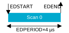
The scan is started with the EDSTART task and the
end indicated with the EDEND event. This
significantly reduces the interrupt frequency and therefore power consumption. The following
figure shows how the ED measurement will operate depending on the EDCNT and EDPERIOD fields
of the EDCTRL register.

The scan is stopped by writing the EDSTOP task. It is followed by the EDSTOPPED event when the module has terminated.
Clear channel assessment (CCA)
IEEE 802.15.4 implements a listen-before-talk channel access method to avoid collisions when transmitting. This is known as carrier sense multiple access with collision avoidance (CSMA-CA). The key part of this method is measuring if the wireless medium is busy or not.
The following clear channel assessment modes are supported:
- CCA Mode 1 (energy above threshold) – The medium is reported busy upon detecting any energy above the ED threshold.
- CCA Mode 2 (carrier sense only) – The medium is reported busy upon detection of a signal compliant with IEEE 802.15.4 with the same modulation and spreading characteristics.
- CCA Mode 3 (carrier sense with energy above threshold) – The medium is reported busy using a logical combination (AND/OR) between the results from CCA Mode 1 and CCA Mode 2.
The clear channel assessment should survey a period equal to 8 symbols or 128 µs.
RADIO must be in RX mode and be able to receive correct packets when performing the CCA. The shortcut between READY and START must be disabled if baseband processing is not to be performed while the measurement is running.
Register EDSAMPLE is updated at the end of the clear channel assessment and can be used to read the energy level measured during the procedure. For CCACTRL.CCAMODE = EdModeEdModeTest1, EDSAMPLE holds the first ED measurement. For the other CCA modes, EDSAMPLE holds the average ED value.
CCA Mode 1
CCA Mode 1 is enabled by first configuring the field CCACTRL.CCAMODE = EdMode and writing the CCACTRL.CCAEDTHRES field to a chosen value. Once the CCASTART task is written, RADIO will perform an ED measurement for 8 symbols and compare the measured level with that found in the CCACTRL.CCAEDTHRES field. If the measured value is higher than or equal to this threshold, the CCABUSY event is generated. If the measured level is less than the threshold, the CCAIDLE event is generated.
CCA Mode 2
CCA Mode 2 is enabled by configuring the field CCACTRL.CCAMODE = CarrierMode. RADIO will sample to see if a valid SFD is found during the 8 symbols. If a valid SFD is detected, the CCABUSY event is generated and the device should not send any data. The CCABUSY event is also generated if the scan was performed during an ongoing frame reception. If the measurement period completes with no SFD detection, the CCAIDLE event is generated. When CCACTRL.CCACORRCNT is not zero, the algorithm will look at the correlator output in addition to the SFD detection signal. If an SFD is reported during the scan period, it will terminate immediately indicating busy medium. Similarly, if the number of peaks above CCACTRL.CCACORRTHRES crosses the CCACTRL.CCACORRCNT, the CCACTRL.CCABUSY event is generated. If less than CCACORRCOUNT crossings are found and no SFD is reported, the CCAIDLE event will be generated and the device can send data.
CCA Mode 3
CCA Mode 3 is enabled by configuring CCACTRL.CCAMODE = CarrierAndEdMode or CCACTRL.CCAMODE = CarrierOrEdMode and performing the required logical combination of the result from CCA Mode 1 and CCA Mode 2. The CCABUSY or CCAIDLE events are generated by ANDing or ORing the energy above threshold and carrier detection scans.
Shortcuts
An ongoing CCA can be stopped by issuing the CCASTOP task. This will trigger the associated CCASTOPPED event.
- To automatically switch between RX mode (when performing the CCA) and to TX mode where the packet is sent, the shortcut between CCAIDLE and TXEN, in conjunction with the short between CCAIDLE and STOP, must be used.
- To automatically disable RADIO whenever the CCA reports a busy medium, the shortcut between CCABUSY and DISABLE can be used.
- To immediately start a CCA after ramping up into RX mode, the shortcut between RXREADY and CCASTART can be used.
Conversion
The conversion from a CCAEDTHRES, LQI, or EDSAMPLE value to dBm can be done with the following equation, where VALHARDWARE is either CCAEDTHRES, LQI, or EDSAMPLE. LQI and EDSAMPLE are hardware-reported values, while CCAEDTHRES is set by software. Constants ED_RSSISCALE and ED_RSSIOFFS are from the electrical specifications.
PRF[dBm] = ED_RSSIOFFS + VALHARDWAREThe ED_RSSISCALE constant is used to calculate power in 802.15.4 units (0-255), using the following formula:
PRF[802.15.4 units] = MIN( ED_RSSISCALE x VALHARDWARE, 255 )Cyclic redundancy check (CRC)
IEEE 802.15.4 uses a 16-bit ITU-T cyclic redundancy check (CRC) calculated over the MAC header (MHR) and MAC service data unit (MSDU).
The standard defines the following generator polynomial:
G(x) = x16 + x12 + x5 + 1
In RX mode, RADIO will trigger the CRC module when the first octet after the frame length (PHR) is received. The CRC will then update on each consecutive octet received. When a complete frame is received, the CRCSTATUS register will be updated accordingly and the CRCOK or CRCERROR events will be generated. When the CRC module is enabled, it will not write the two last octets (CRC) to the frame RAM. When transmitting, the CRC will be computed on the fly, starting with the first octet after PHR, and inserted as the two last octets in the frame. The EasyDMA will fetch the frame length minus 2 octets from RAM and insert the CRC octets at their correct positions in the frame.
The following code shows how to configure the CRC module for correct operation when in IEEE 802.15.4 mode. The CRCCNF is written to 16-bit CRC and the CRCPOLY is written to 0x11021. The start value used by IEEE 802.15.4 is 0 and CRCINIT is configured to reflect this.
/* 16-bit CRC with ITU-T polynomial with 0 as start condition*/
NRF_RADIO->CRCCNF = ((RADIO_CRCCNF_SKIPADDR_Ieee802154 << RADIO_CRCCNF_SKIPADDR_Pos) |
                    (RADIO_CRCCNF_LEN_Two << RADIO_CRCCNF_LEN_Pos));
NRF_RADIO->CRCPOLY = 0x11021;
NRF_RADIO->CRCINIT = 0;
The ENDIANESS subregister must be set to little-endian since the FCS field is transmitted from the left bit to the right bit.
Transmit sequence
The transmission is started by first putting RADIO in RX mode and triggering the RXEN task .
An outline of the IEEE 802.15.4 transmission is illustrated in the following figure.
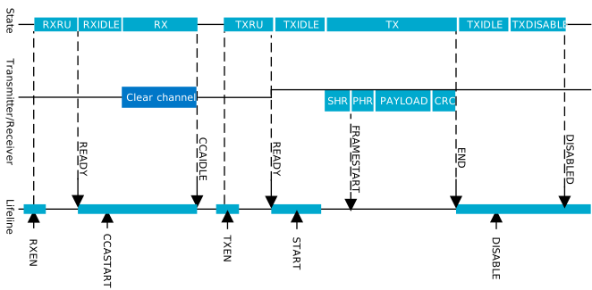
The receiver will ramp up and enter the RXIDLE state where the READY event is generated. Upon receiving the READY event, the CCA is started by triggering the CCASTART task. The chosen mode of assessment (register CCACTRL.CCAMODE) will be performed and signal the CCAIDLE event or CCABUSY event 128 µs later. If the event CCABUSY is received, RADIO will have to retry the CCA after a specific back-off period. This is outlined in the IEEE 802.15.4 standard, Figure 69 in section 7.5.1.4 The CSMA-CA algorithm.
If the event CCAIDLE is generated, a write to the task register TXEN enters RADIO in TXRU state. The READY event will be generated when RADIO is in the TXIDLE state and ready to transmit. With the PACKETPTR pointing to the length (PHR) field of the frame, the START task can be written. RADIO will send the four octet preamble sequence followed by the start of frame delimiter (register SFD). The first byte read from RAM is the length field (PHR) followed by the transmission of the number of bytes indicated as the frame length. If the CRC module is configured, it will run for PHR-2 octets. The last two octets will be substituted with the results from running the CRC. The necessary CRC parameters are sampled on the START task. The FCS field of the frame is little endian.
In addition to the available shortcuts, one is provided between the READY event and the CCASTART task so that a CCA can automatically start when the receiver is ready. A second shortcut has been added between the CCAIDLE event and the TXEN task, when a clear channel is detected, RADIO can immediately enter TX mode.
Receive sequence
RADIO must be in RX mode before the receive sequence can begin. After writing to the RXEN task, RADIO will start ramping up and enter the RXRU state.
When the READY event is generated, RADIO enters the RXIDLE mode. For the baseband processing to be enabled, the START task must be written. An outline of the IEEE 802.15.4 receive sequence can be found in the following figure.
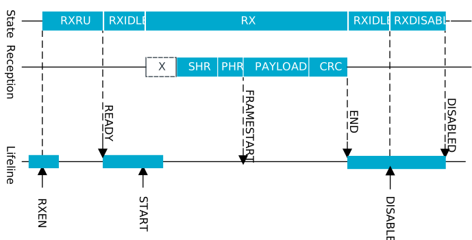
When a valid SHR is received, RADIO will start storing future octets (starting with PHR) to the data memory pointed to by PACKETPTR. After the SFD octet is received, the FRAMESTART event is generated. If the CRC module is enabled, it will start updating with the second byte received (first byte in payload) and run for the full frame length. The two last bytes in the frame are not written to RAM when CRC is configured. However, if the result of the CRC is zero after running the full frame, the CRCOK event will be generated. The END event is generated when the last octet has been received and is available in data memory.
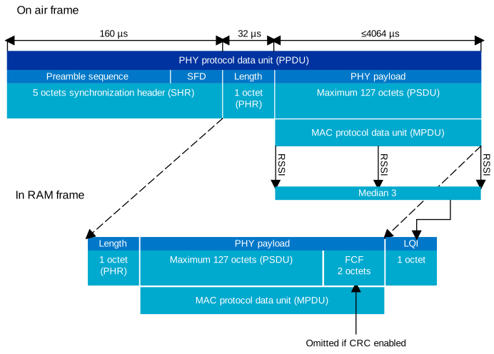
When a packet is received, a link quality indicator (LQI) is generated and appended immediately after the last received octet. When using an IEEE 802.15.4 compliant frame, this will be just after the MSDU since the FCS is not reported. In the case of a non-compliant frame, it will be appended after the full frame. The LQI reported by the hardware must be converted to the IEEE 802.15.4 range by an 8-bit saturating multiplication of 4, as shown in IEEE 802.15.4 ED measurement example. The LQI is only valid for frames equal to, or longer than, three octets. When receiving a frame, the RSSI (reported as negative dB) will be measured at three points during the reception. These three values will be sorted with the middle value selected (median 3) to be remapped within the LQI range. The following figure illustrates the LQI measurement and how the data is arranged in data memory.
A shortcut has been added between the FRAMESTART event and the BCSTART task. This can be used to trigger a BCMATCH event after N bits, such as when inspecting the MAC addressing fields.
Interframe spacing (IFS)
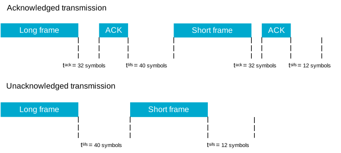
IEEE 802.15.4 defines a specific time that is allotted for the MAC sublayer to process received data. The interframe spacing (IFS) is used to prevent two frames from being transmitted too close together. If the transmission is requesting an acknowledgement, the space before the second frame must be at least one IFS period.
- IFS = macMinSIFSPeriod (12 symbols) if MPDU ≤ aMaxSIFSFrameSize (18 octets) octets
- IFS = macMinLIFSPeriod (40 symbols) if MPDU > aMaxSIFSFrameSize
Using the efficient assisted modes in RADIO, the TIFS will be programmed with the correct value based on the frame being transmitted. If the assisted modes are not in use, the TIFS register must be updated manually. The following figure shows what IFS period is valid in both acknowledged and unacknowledged transmissions.
EasyDMA
RADIO uses EasyDMA to read and write packets to RAM without CPU involvement.
As illustrated in RADIO block diagram, the RADIO peripheral's EasyDMA utilizes the same PACKETPTR for receiving and transmitting packets. This pointer should be reconfigured by the CPU each time before RADIO is started by the START task. The PACKETPTR register is double-buffered, meaning that it can be updated and prepared for the next transmission.
The END event indicates that the last bit has been processed by RADIO. The DISABLED event is issued to acknowledge that the DISABLE task is done.
The structure of a packet is described in detail in Packet configuration. The data that is stored in Data RAM and transported by EasyDMA consists of the following fields:
- S0
- LENGTH
- S1
- PAYLOAD
In addition, a static add-on is sent immediately after the payload.
The size of each of the listed fields in the frame is configurable (see Packet configuration), and the space occupied in RAM depends on these settings. The size of the field can be zero, as long as the resulting frame complies with the chosen RF protocol.
All fields are extended in size to align with a byte boundary in RAM. For instance, a 3-bit long field on-air will occupy 1 byte in RAM while a 9-bit long field will be extended to 2 bytes.
- CI, TERM1, and TERM2 fields are only present in Bluetooth Low Energy Long Range mode
- S0 is configured through the field PCNF0.S0LEN
- LENGTH is configured through the field PCNF0.LFLEN
- S1 is configured through the field PCNF0.S1LEN
- Payload size is configured through the value in RAM corresponding to the LENGTH field
- Static add-on size is configured through the field PCNF1.STATLEN
The PCNF1.MAXLEN field configures the maximum packet payload plus add-on size in number of bytes that can be transmitted or received by RADIO. This feature can be used to ensure that RADIO does not overwrite or read beyond the RAM assigned to the packet payload. This means that if the LENGTH field of the packet payload exceeds PCNF1.STATLEN, and the LENGTH field in the packet specifies a packet larger than configured in PCNF1.MAXLEN, the payload will be truncated to the length specified in PCNF1.MAXLEN.
If the payload and add-on length is specified larger than PCNF1.MAXLEN, RADIO will transmit or receive in the same way as before, except the payload is now truncated to PCNF1.MAXLEN. The packet's LENGTH field will not be altered when the payload is truncated. RADIO will calculate CRC as if the packet length is equal to PCNF1.MAXLEN.
The END event indicates that the last bit has been processed by RADIO. The DISABLED event is issued to acknowledge that the DISABLE task is done.
Registers
Instances
| Instance | Domain | Base address | TrustZone | Split access | Description | ||
|---|---|---|---|---|---|---|---|
| Map | Att | DMA | |||||
RADIO : S | GLOBAL | 0x5008A000 | US | S | SA | No | 2.4 GHz radio RADIO See pinout for GPIO options for DFE antenna switch control |
Configuration
| Instance | Domain | Configuration |
|---|---|---|
RADIO : S | GLOBAL | For the PSEL registers, use only dedicated pins on port P1 |
Register overview
| Register | Offset | TZ | Description |
|---|---|---|---|
| TASKS_TXEN | 0x000 | Enable RADIO in TX mode | |
| TASKS_RXEN | 0x004 | Enable RADIO in RX mode | |
| TASKS_START | 0x008 | Start RADIO | |
| TASKS_STOP | 0x00C | Stop RADIO | |
| TASKS_DISABLE | 0x010 | Disable RADIO | |
| TASKS_RSSISTART | 0x014 | Start the RSSI and take one single sample of the receive signal strength | |
| TASKS_BCSTART | 0x018 | Start the bit counter | |
| TASKS_BCSTOP | 0x01C | Stop the bit counter | |
| TASKS_EDSTART | 0x020 | Start the energy detect measurement used in IEEE 802.15.4 mode | |
| TASKS_EDSTOP | 0x024 | Stop the energy detect measurement | |
| TASKS_CCASTART | 0x028 | Start the clear channel assessment used in IEEE 802.15.4 mode | |
| TASKS_CCASTOP | 0x02C | Stop the clear channel assessment | |
| TASKS_AUXDATADMASTART | 0x038 | Start DMA transaction of acquisition | |
| TASKS_AUXDATADMASTOP | 0x03C | Stop ongoing DMA transaction of acquisition | |
| TASKS_PLLEN | 0x06C | Enable RADIO in PLL mode (standby for either TX or RX) | |
| TASKS_CSTONESSTART | 0x0A0 | Start tone processing for channel sounding | |
| TASKS_SOFTRESET | 0x0A4 | Reset all public registers, but with these exceptions: DMA registers and EVENT/INTEN/SUBSCRIBE/PUBLISH registers. Only to be used in DISABLED state. | |
| SUBSCRIBE_TXEN | 0x100 | Subscribe configuration for task TXEN | |
| SUBSCRIBE_RXEN | 0x104 | Subscribe configuration for task RXEN | |
| SUBSCRIBE_START | 0x108 | Subscribe configuration for task START | |
| SUBSCRIBE_STOP | 0x10C | Subscribe configuration for task STOP | |
| SUBSCRIBE_DISABLE | 0x110 | Subscribe configuration for task DISABLE | |
| SUBSCRIBE_RSSISTART | 0x114 | Subscribe configuration for task RSSISTART | |
| SUBSCRIBE_BCSTART | 0x118 | Subscribe configuration for task BCSTART | |
| SUBSCRIBE_BCSTOP | 0x11C | Subscribe configuration for task BCSTOP | |
| SUBSCRIBE_EDSTART | 0x120 | Subscribe configuration for task EDSTART | |
| SUBSCRIBE_EDSTOP | 0x124 | Subscribe configuration for task EDSTOP | |
| SUBSCRIBE_CCASTART | 0x128 | Subscribe configuration for task CCASTART | |
| SUBSCRIBE_CCASTOP | 0x12C | Subscribe configuration for task CCASTOP | |
| SUBSCRIBE_AUXDATADMASTART | 0x138 | Subscribe configuration for task AUXDATADMASTART | |
| SUBSCRIBE_AUXDATADMASTOP | 0x13C | Subscribe configuration for task AUXDATADMASTOP | |
| SUBSCRIBE_PLLEN | 0x16C | Subscribe configuration for task PLLEN | |
| SUBSCRIBE_CSTONESSTART | 0x1A0 | Subscribe configuration for task CSTONESSTART | |
| SUBSCRIBE_SOFTRESET | 0x1A4 | Subscribe configuration for task SOFTRESET | |
| EVENTS_READY | 0x200 | RADIO has ramped up and is ready to be started | |
| EVENTS_TXREADY | 0x204 | RADIO has ramped up and is ready to be started TX path | |
| EVENTS_RXREADY | 0x208 | RADIO has ramped up and is ready to be started RX path | |
| EVENTS_ADDRESS | 0x20C | Address sent or received | |
| EVENTS_FRAMESTART | 0x210 | IEEE 802.15.4 length field received | |
| EVENTS_PAYLOAD | 0x214 | Packet payload sent or received | |
| EVENTS_END | 0x218 | Memory access for packet data has been completed | |
| EVENTS_PHYEND | 0x21C | The last bit is sent on air or last bit is received | |
| EVENTS_DISABLED | 0x220 | RADIO has been disabled | |
| EVENTS_DEVMATCH | 0x224 | A device address match occurred on the last received packet | |
| EVENTS_DEVMISS | 0x228 | No device address match occurred on the last received packet | |
| EVENTS_CRCOK | 0x22C | Packet received with CRC ok | |
| EVENTS_CRCERROR | 0x230 | Packet received with CRC error | |
| EVENTS_BCMATCH | 0x238 | Bit counter reached bit count value | |
| EVENTS_EDEND | 0x23C | Sampling of energy detection complete (a new ED sample is ready for readout from the RADIO.EDSAMPLE register) | |
| EVENTS_EDSTOPPED | 0x240 | The sampling of energy detection has stopped | |
| EVENTS_CCAIDLE | 0x244 | Wireless medium in idle - clear to send | |
| EVENTS_CCABUSY | 0x248 | Wireless medium busy - do not send | |
| EVENTS_CCASTOPPED | 0x24C | The CCA has stopped | |
| EVENTS_RATEBOOST | 0x250 | Ble_LR CI field received, receive mode is changed from Ble_LR125Kbit to Ble_LR500Kbit | |
| EVENTS_MHRMATCH | 0x254 | MAC header match found | |
| EVENTS_SYNC | 0x258 | Initial sync detected | |
| EVENTS_CTEPRESENT | 0x25C | CTEInfo byte is received | |
| EVENTS_PLLREADY | 0x2B0 | PLL has settled and RADIO is ready to be enabled in either TX or RX mode | |
| EVENTS_RXADDRESS | 0x2BC | Address received | |
| EVENTS_AUXDATADMAEND | 0x2C0 | AUXDATA DMA end | |
| EVENTS_CSTONESEND | 0x2C8 | The channel sounding tone processing is complete | |
| PUBLISH_READY | 0x300 | Publish configuration for event READY | |
| PUBLISH_TXREADY | 0x304 | Publish configuration for event TXREADY | |
| PUBLISH_RXREADY | 0x308 | Publish configuration for event RXREADY | |
| PUBLISH_ADDRESS | 0x30C | Publish configuration for event ADDRESS | |
| PUBLISH_FRAMESTART | 0x310 | Publish configuration for event FRAMESTART | |
| PUBLISH_PAYLOAD | 0x314 | Publish configuration for event PAYLOAD | |
| PUBLISH_END | 0x318 | Publish configuration for event END | |
| PUBLISH_PHYEND | 0x31C | Publish configuration for event PHYEND | |
| PUBLISH_DISABLED | 0x320 | Publish configuration for event DISABLED | |
| PUBLISH_DEVMATCH | 0x324 | Publish configuration for event DEVMATCH | |
| PUBLISH_DEVMISS | 0x328 | Publish configuration for event DEVMISS | |
| PUBLISH_CRCOK | 0x32C | Publish configuration for event CRCOK | |
| PUBLISH_CRCERROR | 0x330 | Publish configuration for event CRCERROR | |
| PUBLISH_BCMATCH | 0x338 | Publish configuration for event BCMATCH | |
| PUBLISH_EDEND | 0x33C | Publish configuration for event EDEND | |
| PUBLISH_EDSTOPPED | 0x340 | Publish configuration for event EDSTOPPED | |
| PUBLISH_CCAIDLE | 0x344 | Publish configuration for event CCAIDLE | |
| PUBLISH_CCABUSY | 0x348 | Publish configuration for event CCABUSY | |
| PUBLISH_CCASTOPPED | 0x34C | Publish configuration for event CCASTOPPED | |
| PUBLISH_RATEBOOST | 0x350 | Publish configuration for event RATEBOOST | |
| PUBLISH_MHRMATCH | 0x354 | Publish configuration for event MHRMATCH | |
| PUBLISH_SYNC | 0x358 | Publish configuration for event SYNC | |
| PUBLISH_CTEPRESENT | 0x35C | Publish configuration for event CTEPRESENT | |
| PUBLISH_PLLREADY | 0x3B0 | Publish configuration for event PLLREADY | |
| PUBLISH_RXADDRESS | 0x3BC | Publish configuration for event RXADDRESS | |
| PUBLISH_AUXDATADMAEND | 0x3C0 | Publish configuration for event AUXDATADMAEND | |
| PUBLISH_CSTONESEND | 0x3C8 | Publish configuration for event CSTONESEND | |
| SHORTS | 0x400 | Shortcuts between local events and tasks | |
| INTENSET00 | 0x488 | Enable interrupt | |
| INTENSET01 | 0x48C | Enable interrupt | |
| INTENCLR00 | 0x490 | Disable interrupt | |
| INTENCLR01 | 0x494 | Disable interrupt | |
| INTENSET10 | 0x4A8 | Enable interrupt | |
| INTENSET11 | 0x4AC | Enable interrupt | |
| INTENCLR10 | 0x4B0 | Disable interrupt | |
| INTENCLR11 | 0x4B4 | Disable interrupt | |
| MODE | 0x500 | Data rate and modulation | |
| PHYENDTXDELAY | 0x518 | Configurable delay of PHYEND event for TX | |
| STATE | 0x520 | Current radio state | |
| EDCTRL | 0x530 | IEEE 802.15.4 energy detect control | |
| EDSAMPLE | 0x534 | IEEE 802.15.4 energy detect level | |
| CCACTRL | 0x538 | IEEE 802.15.4 clear channel assessment control | |
| DATAWHITE | 0x540 | Data whitening configuration | |
| AUXDATA.CNF[n] | 0x548 | AUXDATA configuration | |
| AUXDATADMA[n].ENABLE | 0x550 | Enable or disable data acquisition | |
| AUXDATADMA[n].PTR | 0x554 | DMA pointer | |
| AUXDATADMA[n].MAXCNT | 0x558 | Maximum number of 32-bit words to transfer | |
| AUXDATADMA[n].AMOUNT | 0x55C | Number of 32-bit words transferred in the last transaction | |
| TIMING | 0x704 | Timing | |
| FREQUENCY | 0x708 | Frequency | |
| TXPOWER | 0x710 | Output power | |
| TIFS | 0x714 | Interframe spacing in µs | |
| RSSISAMPLE | 0x718 | RSSI sample | |
| RXGAIN.CONFIG | 0x7D4 | Override configuration of receiver gain control loop | |
| FREQFINETUNE | 0x0804 | Fine tuning of the RF frequency | |
| FECONFIG | 0x908 | Config register | |
| CFO_STAT | 0xB00 | Carrier freq. offset estimate | |
| DBCCORR | 0xB40 | Correlator thresholds | |
| DFEMODE | 0xD00 | Whether to use Angle-of-Arrival (AOA) or Angle-of-Departure (AOD) | |
| DFESTATUS | 0xD04 | DFE status information | |
| DFECTRL1 | 0xD10 | Various configuration for Direction finding | |
| DFECTRL2 | 0xD14 | Start offset for Direction finding | |
| SWITCHPATTERN | 0xD28 | GPIO patterns to be used for each antenna | |
| CLEARPATTERN | 0xD2C | Clear the GPIO pattern array for antenna control | |
| PSEL.DFEGPIO[n] | 0xD30 | Pin select for DFE pin n | |
| DFEPACKET.PTR | 0xD50 | Data pointer | |
| DFEPACKET.MAXCNT | 0xD54 | Maximum number of bytes to transfer | |
| DFEPACKET.AMOUNT | 0xD58 | Number of bytes transferred in the last transaction | |
| DFEPACKET.CURRENTAMOUNT | 0xD5C | Number of bytes transferred in the current transaction | |
| CRCSTATUS | 0xE0C | CRC status | |
| RXMATCH | 0xE10 | Received address | |
| RXCRC | 0xE14 | CRC field of previously received packet | |
| DAI | 0xE18 | Device address match index | |
| PDUSTAT | 0xE1C | Payload status | |
| PCNF0 | 0xE20 | Packet configuration register 0 | |
| PCNF1 | 0xE28 | Packet configuration register 1 | |
| BASE0 | 0xE2C | Base address 0 | |
| BASE1 | 0xE30 | Base address 1 | |
| PREFIX0 | 0xE34 | Prefixes bytes for logical addresses 0-3 | |
| PREFIX1 | 0xE38 | Prefixes bytes for logical addresses 4-7 | |
| TXADDRESS | 0xE3C | Transmit address select | |
| RXADDRESSES | 0xE40 | Receive address select | |
| CRCCNF | 0xE44 | CRC configuration | |
| CRCPOLY | 0xE48 | CRC polynomial | |
| CRCINIT | 0xE4C | CRC initial value | |
| DAB[n] | 0xE50 | Device address base segment n | |
| DAP[n] | 0xE70 | Device address prefix n | |
| DACNF | 0xE90 | Device address match configuration | |
| BCC | 0xE94 | Bit counter compare | |
| CTESTATUS | 0xEA4 | CTEInfo parsed from received packet | |
| MHRMATCHCONF | 0xEB4 | Search pattern configuration | |
| MHRMATCHMASK | 0xEB8 | Pattern mask | |
| SFD | 0xEBC | IEEE 802.15.4 start of frame delimiter | |
| CTEINLINECONF | 0xEC0 | Configuration for CTE inline mode | |
| PACKETPTR | 0xED0 | Packet pointer | |
| CSTONES.MODE | 0x1000 | Selects the mode(s) that are activated on the start signal | |
| CSTONES.NUMSAMPLES | 0x1004 | Number of input samples at 2MHz sample rate | |
| CSTONES.NEXTFREQUENCY | 0x1008 | The value of FREQUENCY that will be used in the next step | |
| CSTONES.FAEPEER | 0x1014 | FAEPEER (Frequency Actuation Error) of peer if known. Used during Mode 0 steps. | |
| CSTONES.PHASESHIFT | 0x1018 | Parameter used in TPM, provided by software | |
| CSTONES.NUMSAMPLESCOEFF | 0x101C | Parameter used in TPM, provided by software | |
| CSTONES.PCT16 | 0x1020 | Mean magnitude and mean phase converted to IQ | |
| CSTONES.MAGPHASEMEAN | 0x1024 | Mean magnitude and phase of the signal before it is converted to PCT16 | |
| CSTONES.IQRAWMEAN | 0x1028 | Mean of IQ values | |
| CSTONES.MAGSTD | 0x102C | Magnitude standard deviation approximation | |
| CSTONES.FFOEST | 0x1034 | FFO estimate | |
| CSTONES.DOWNSAMPLE | 0x1038 | Turn on/off down sample of input IQ-signals | |
| CSTONES.FREQOFFSET | 0x1044 | Frequency offset estimate | |
| RTT.CONFIG | 0x1050 | RTT Config. | |
| RTT.SEGMENT01 | 0x1054 | RTT segments 0 and 1 | |
| RTT.SEGMENT23 | 0x1058 | RTT segments 2 and 3 | |
| RTT.SEGMENT45 | 0x105C | RTT segments 4 and 5 | |
| RTT.SEGMENT67 | 0x1060 | RTT segments 6 and 7 |
TASKS_TXEN
Address offset: 0x000
Enable RADIO in TX mode
| Bit number | 31 | 30 | 29 | 28 | 27 | 26 | 25 | 24 | 23 | 22 | 21 | 20 | 19 | 18 | 17 | 16 | 15 | 14 | 13 | 12 | 11 | 10 | 9 | 8 | 7 | 6 | 5 | 4 | 3 | 2 | 1 | 0 | |||
|---|---|---|---|---|---|---|---|---|---|---|---|---|---|---|---|---|---|---|---|---|---|---|---|---|---|---|---|---|---|---|---|---|---|---|---|
| ID | A | ||||||||||||||||||||||||||||||||||
| Reset 0x00000000 | 0 | 0 | 0 | 0 | 0 | 0 | 0 | 0 | 0 | 0 | 0 | 0 | 0 | 0 | 0 | 0 | 0 | 0 | 0 | 0 | 0 | 0 | 0 | 0 | 0 | 0 | 0 | 0 | 0 | 0 | 0 | 0 | |||
| ID | R/W | Field | Value ID | Value | Description | ||||||||||||||||||||||||||||||
| A | W | TASKS_TXEN | Enable RADIO in TX mode | ||||||||||||||||||||||||||||||||
Trigger | 1 | Trigger task | |||||||||||||||||||||||||||||||||
TASKS_RXEN
Address offset: 0x004
Enable RADIO in RX mode
| Bit number | 31 | 30 | 29 | 28 | 27 | 26 | 25 | 24 | 23 | 22 | 21 | 20 | 19 | 18 | 17 | 16 | 15 | 14 | 13 | 12 | 11 | 10 | 9 | 8 | 7 | 6 | 5 | 4 | 3 | 2 | 1 | 0 | |||
|---|---|---|---|---|---|---|---|---|---|---|---|---|---|---|---|---|---|---|---|---|---|---|---|---|---|---|---|---|---|---|---|---|---|---|---|
| ID | A | ||||||||||||||||||||||||||||||||||
| Reset 0x00000000 | 0 | 0 | 0 | 0 | 0 | 0 | 0 | 0 | 0 | 0 | 0 | 0 | 0 | 0 | 0 | 0 | 0 | 0 | 0 | 0 | 0 | 0 | 0 | 0 | 0 | 0 | 0 | 0 | 0 | 0 | 0 | 0 | |||
| ID | R/W | Field | Value ID | Value | Description | ||||||||||||||||||||||||||||||
| A | W | TASKS_RXEN | Enable RADIO in RX mode | ||||||||||||||||||||||||||||||||
Trigger | 1 | Trigger task | |||||||||||||||||||||||||||||||||
TASKS_START
Address offset: 0x008
Start RADIO
| Bit number | 31 | 30 | 29 | 28 | 27 | 26 | 25 | 24 | 23 | 22 | 21 | 20 | 19 | 18 | 17 | 16 | 15 | 14 | 13 | 12 | 11 | 10 | 9 | 8 | 7 | 6 | 5 | 4 | 3 | 2 | 1 | 0 | |||
|---|---|---|---|---|---|---|---|---|---|---|---|---|---|---|---|---|---|---|---|---|---|---|---|---|---|---|---|---|---|---|---|---|---|---|---|
| ID | A | ||||||||||||||||||||||||||||||||||
| Reset 0x00000000 | 0 | 0 | 0 | 0 | 0 | 0 | 0 | 0 | 0 | 0 | 0 | 0 | 0 | 0 | 0 | 0 | 0 | 0 | 0 | 0 | 0 | 0 | 0 | 0 | 0 | 0 | 0 | 0 | 0 | 0 | 0 | 0 | |||
| ID | R/W | Field | Value ID | Value | Description | ||||||||||||||||||||||||||||||
| A | W | TASKS_START | Start RADIO | ||||||||||||||||||||||||||||||||
Trigger | 1 | Trigger task | |||||||||||||||||||||||||||||||||
TASKS_STOP
Address offset: 0x00C
Stop RADIO
| Bit number | 31 | 30 | 29 | 28 | 27 | 26 | 25 | 24 | 23 | 22 | 21 | 20 | 19 | 18 | 17 | 16 | 15 | 14 | 13 | 12 | 11 | 10 | 9 | 8 | 7 | 6 | 5 | 4 | 3 | 2 | 1 | 0 | |||
|---|---|---|---|---|---|---|---|---|---|---|---|---|---|---|---|---|---|---|---|---|---|---|---|---|---|---|---|---|---|---|---|---|---|---|---|
| ID | A | ||||||||||||||||||||||||||||||||||
| Reset 0x00000000 | 0 | 0 | 0 | 0 | 0 | 0 | 0 | 0 | 0 | 0 | 0 | 0 | 0 | 0 | 0 | 0 | 0 | 0 | 0 | 0 | 0 | 0 | 0 | 0 | 0 | 0 | 0 | 0 | 0 | 0 | 0 | 0 | |||
| ID | R/W | Field | Value ID | Value | Description | ||||||||||||||||||||||||||||||
| A | W | TASKS_STOP | Stop RADIO | ||||||||||||||||||||||||||||||||
Trigger | 1 | Trigger task | |||||||||||||||||||||||||||||||||
TASKS_DISABLE
Address offset: 0x010
Disable RADIO
| Bit number | 31 | 30 | 29 | 28 | 27 | 26 | 25 | 24 | 23 | 22 | 21 | 20 | 19 | 18 | 17 | 16 | 15 | 14 | 13 | 12 | 11 | 10 | 9 | 8 | 7 | 6 | 5 | 4 | 3 | 2 | 1 | 0 | |||
|---|---|---|---|---|---|---|---|---|---|---|---|---|---|---|---|---|---|---|---|---|---|---|---|---|---|---|---|---|---|---|---|---|---|---|---|
| ID | A | ||||||||||||||||||||||||||||||||||
| Reset 0x00000000 | 0 | 0 | 0 | 0 | 0 | 0 | 0 | 0 | 0 | 0 | 0 | 0 | 0 | 0 | 0 | 0 | 0 | 0 | 0 | 0 | 0 | 0 | 0 | 0 | 0 | 0 | 0 | 0 | 0 | 0 | 0 | 0 | |||
| ID | R/W | Field | Value ID | Value | Description | ||||||||||||||||||||||||||||||
| A | W | TASKS_DISABLE | Disable RADIO | ||||||||||||||||||||||||||||||||
Trigger | 1 | Trigger task | |||||||||||||||||||||||||||||||||
TASKS_RSSISTART
Address offset: 0x014
Start the RSSI and take one single sample of the receive signal strength
| Bit number | 31 | 30 | 29 | 28 | 27 | 26 | 25 | 24 | 23 | 22 | 21 | 20 | 19 | 18 | 17 | 16 | 15 | 14 | 13 | 12 | 11 | 10 | 9 | 8 | 7 | 6 | 5 | 4 | 3 | 2 | 1 | 0 | |||
|---|---|---|---|---|---|---|---|---|---|---|---|---|---|---|---|---|---|---|---|---|---|---|---|---|---|---|---|---|---|---|---|---|---|---|---|
| ID | A | ||||||||||||||||||||||||||||||||||
| Reset 0x00000000 | 0 | 0 | 0 | 0 | 0 | 0 | 0 | 0 | 0 | 0 | 0 | 0 | 0 | 0 | 0 | 0 | 0 | 0 | 0 | 0 | 0 | 0 | 0 | 0 | 0 | 0 | 0 | 0 | 0 | 0 | 0 | 0 | |||
| ID | R/W | Field | Value ID | Value | Description | ||||||||||||||||||||||||||||||
| A | W | TASKS_RSSISTART | Start the RSSI and take one single sample of the receive signal strength | ||||||||||||||||||||||||||||||||
Trigger | 1 | Trigger task | |||||||||||||||||||||||||||||||||
TASKS_BCSTART
Address offset: 0x018
Start the bit counter
| Bit number | 31 | 30 | 29 | 28 | 27 | 26 | 25 | 24 | 23 | 22 | 21 | 20 | 19 | 18 | 17 | 16 | 15 | 14 | 13 | 12 | 11 | 10 | 9 | 8 | 7 | 6 | 5 | 4 | 3 | 2 | 1 | 0 | |||
|---|---|---|---|---|---|---|---|---|---|---|---|---|---|---|---|---|---|---|---|---|---|---|---|---|---|---|---|---|---|---|---|---|---|---|---|
| ID | A | ||||||||||||||||||||||||||||||||||
| Reset 0x00000000 | 0 | 0 | 0 | 0 | 0 | 0 | 0 | 0 | 0 | 0 | 0 | 0 | 0 | 0 | 0 | 0 | 0 | 0 | 0 | 0 | 0 | 0 | 0 | 0 | 0 | 0 | 0 | 0 | 0 | 0 | 0 | 0 | |||
| ID | R/W | Field | Value ID | Value | Description | ||||||||||||||||||||||||||||||
| A | W | TASKS_BCSTART | Start the bit counter | ||||||||||||||||||||||||||||||||
Trigger | 1 | Trigger task | |||||||||||||||||||||||||||||||||
TASKS_BCSTOP
Address offset: 0x01C
Stop the bit counter
| Bit number | 31 | 30 | 29 | 28 | 27 | 26 | 25 | 24 | 23 | 22 | 21 | 20 | 19 | 18 | 17 | 16 | 15 | 14 | 13 | 12 | 11 | 10 | 9 | 8 | 7 | 6 | 5 | 4 | 3 | 2 | 1 | 0 | |||
|---|---|---|---|---|---|---|---|---|---|---|---|---|---|---|---|---|---|---|---|---|---|---|---|---|---|---|---|---|---|---|---|---|---|---|---|
| ID | A | ||||||||||||||||||||||||||||||||||
| Reset 0x00000000 | 0 | 0 | 0 | 0 | 0 | 0 | 0 | 0 | 0 | 0 | 0 | 0 | 0 | 0 | 0 | 0 | 0 | 0 | 0 | 0 | 0 | 0 | 0 | 0 | 0 | 0 | 0 | 0 | 0 | 0 | 0 | 0 | |||
| ID | R/W | Field | Value ID | Value | Description | ||||||||||||||||||||||||||||||
| A | W | TASKS_BCSTOP | Stop the bit counter | ||||||||||||||||||||||||||||||||
Trigger | 1 | Trigger task | |||||||||||||||||||||||||||||||||
TASKS_EDSTART
Address offset: 0x020
Start the energy detect measurement used in IEEE 802.15.4 mode
| Bit number | 31 | 30 | 29 | 28 | 27 | 26 | 25 | 24 | 23 | 22 | 21 | 20 | 19 | 18 | 17 | 16 | 15 | 14 | 13 | 12 | 11 | 10 | 9 | 8 | 7 | 6 | 5 | 4 | 3 | 2 | 1 | 0 | |||
|---|---|---|---|---|---|---|---|---|---|---|---|---|---|---|---|---|---|---|---|---|---|---|---|---|---|---|---|---|---|---|---|---|---|---|---|
| ID | A | ||||||||||||||||||||||||||||||||||
| Reset 0x00000000 | 0 | 0 | 0 | 0 | 0 | 0 | 0 | 0 | 0 | 0 | 0 | 0 | 0 | 0 | 0 | 0 | 0 | 0 | 0 | 0 | 0 | 0 | 0 | 0 | 0 | 0 | 0 | 0 | 0 | 0 | 0 | 0 | |||
| ID | R/W | Field | Value ID | Value | Description | ||||||||||||||||||||||||||||||
| A | W | TASKS_EDSTART | Start the energy detect measurement used in IEEE 802.15.4 mode | ||||||||||||||||||||||||||||||||
Trigger | 1 | Trigger task | |||||||||||||||||||||||||||||||||
TASKS_EDSTOP
Address offset: 0x024
Stop the energy detect measurement
| Bit number | 31 | 30 | 29 | 28 | 27 | 26 | 25 | 24 | 23 | 22 | 21 | 20 | 19 | 18 | 17 | 16 | 15 | 14 | 13 | 12 | 11 | 10 | 9 | 8 | 7 | 6 | 5 | 4 | 3 | 2 | 1 | 0 | |||
|---|---|---|---|---|---|---|---|---|---|---|---|---|---|---|---|---|---|---|---|---|---|---|---|---|---|---|---|---|---|---|---|---|---|---|---|
| ID | A | ||||||||||||||||||||||||||||||||||
| Reset 0x00000000 | 0 | 0 | 0 | 0 | 0 | 0 | 0 | 0 | 0 | 0 | 0 | 0 | 0 | 0 | 0 | 0 | 0 | 0 | 0 | 0 | 0 | 0 | 0 | 0 | 0 | 0 | 0 | 0 | 0 | 0 | 0 | 0 | |||
| ID | R/W | Field | Value ID | Value | Description | ||||||||||||||||||||||||||||||
| A | W | TASKS_EDSTOP | Stop the energy detect measurement | ||||||||||||||||||||||||||||||||
Trigger | 1 | Trigger task | |||||||||||||||||||||||||||||||||
TASKS_CCASTART
Address offset: 0x028
Start the clear channel assessment used in IEEE 802.15.4 mode
| Bit number | 31 | 30 | 29 | 28 | 27 | 26 | 25 | 24 | 23 | 22 | 21 | 20 | 19 | 18 | 17 | 16 | 15 | 14 | 13 | 12 | 11 | 10 | 9 | 8 | 7 | 6 | 5 | 4 | 3 | 2 | 1 | 0 | |||
|---|---|---|---|---|---|---|---|---|---|---|---|---|---|---|---|---|---|---|---|---|---|---|---|---|---|---|---|---|---|---|---|---|---|---|---|
| ID | A | ||||||||||||||||||||||||||||||||||
| Reset 0x00000000 | 0 | 0 | 0 | 0 | 0 | 0 | 0 | 0 | 0 | 0 | 0 | 0 | 0 | 0 | 0 | 0 | 0 | 0 | 0 | 0 | 0 | 0 | 0 | 0 | 0 | 0 | 0 | 0 | 0 | 0 | 0 | 0 | |||
| ID | R/W | Field | Value ID | Value | Description | ||||||||||||||||||||||||||||||
| A | W | TASKS_CCASTART | Start the clear channel assessment used in IEEE 802.15.4 mode | ||||||||||||||||||||||||||||||||
Trigger | 1 | Trigger task | |||||||||||||||||||||||||||||||||
TASKS_CCASTOP
Address offset: 0x02C
Stop the clear channel assessment
| Bit number | 31 | 30 | 29 | 28 | 27 | 26 | 25 | 24 | 23 | 22 | 21 | 20 | 19 | 18 | 17 | 16 | 15 | 14 | 13 | 12 | 11 | 10 | 9 | 8 | 7 | 6 | 5 | 4 | 3 | 2 | 1 | 0 | |||
|---|---|---|---|---|---|---|---|---|---|---|---|---|---|---|---|---|---|---|---|---|---|---|---|---|---|---|---|---|---|---|---|---|---|---|---|
| ID | A | ||||||||||||||||||||||||||||||||||
| Reset 0x00000000 | 0 | 0 | 0 | 0 | 0 | 0 | 0 | 0 | 0 | 0 | 0 | 0 | 0 | 0 | 0 | 0 | 0 | 0 | 0 | 0 | 0 | 0 | 0 | 0 | 0 | 0 | 0 | 0 | 0 | 0 | 0 | 0 | |||
| ID | R/W | Field | Value ID | Value | Description | ||||||||||||||||||||||||||||||
| A | W | TASKS_CCASTOP | Stop the clear channel assessment | ||||||||||||||||||||||||||||||||
Trigger | 1 | Trigger task | |||||||||||||||||||||||||||||||||
TASKS_AUXDATADMASTART
Address offset: 0x038
Start DMA transaction of acquisition
| Bit number | 31 | 30 | 29 | 28 | 27 | 26 | 25 | 24 | 23 | 22 | 21 | 20 | 19 | 18 | 17 | 16 | 15 | 14 | 13 | 12 | 11 | 10 | 9 | 8 | 7 | 6 | 5 | 4 | 3 | 2 | 1 | 0 | |||
|---|---|---|---|---|---|---|---|---|---|---|---|---|---|---|---|---|---|---|---|---|---|---|---|---|---|---|---|---|---|---|---|---|---|---|---|
| ID | A | ||||||||||||||||||||||||||||||||||
| Reset 0x00000000 | 0 | 0 | 0 | 0 | 0 | 0 | 0 | 0 | 0 | 0 | 0 | 0 | 0 | 0 | 0 | 0 | 0 | 0 | 0 | 0 | 0 | 0 | 0 | 0 | 0 | 0 | 0 | 0 | 0 | 0 | 0 | 0 | |||
| ID | R/W | Field | Value ID | Value | Description | ||||||||||||||||||||||||||||||
| A | W | TASKS_AUXDATADMASTART | Start DMA transaction of acquisition | ||||||||||||||||||||||||||||||||
Trigger | 1 | Trigger task | |||||||||||||||||||||||||||||||||
TASKS_AUXDATADMASTOP
Address offset: 0x03C
Stop ongoing DMA transaction of acquisition
| Bit number | 31 | 30 | 29 | 28 | 27 | 26 | 25 | 24 | 23 | 22 | 21 | 20 | 19 | 18 | 17 | 16 | 15 | 14 | 13 | 12 | 11 | 10 | 9 | 8 | 7 | 6 | 5 | 4 | 3 | 2 | 1 | 0 | |||
|---|---|---|---|---|---|---|---|---|---|---|---|---|---|---|---|---|---|---|---|---|---|---|---|---|---|---|---|---|---|---|---|---|---|---|---|
| ID | A | ||||||||||||||||||||||||||||||||||
| Reset 0x00000000 | 0 | 0 | 0 | 0 | 0 | 0 | 0 | 0 | 0 | 0 | 0 | 0 | 0 | 0 | 0 | 0 | 0 | 0 | 0 | 0 | 0 | 0 | 0 | 0 | 0 | 0 | 0 | 0 | 0 | 0 | 0 | 0 | |||
| ID | R/W | Field | Value ID | Value | Description | ||||||||||||||||||||||||||||||
| A | W | TASKS_AUXDATADMASTOP | Stop ongoing DMA transaction of acquisition | ||||||||||||||||||||||||||||||||
Trigger | 1 | Trigger task | |||||||||||||||||||||||||||||||||
TASKS_PLLEN
Address offset: 0x06C
Enable RADIO in PLL mode (standby for either TX or RX)
| Bit number | 31 | 30 | 29 | 28 | 27 | 26 | 25 | 24 | 23 | 22 | 21 | 20 | 19 | 18 | 17 | 16 | 15 | 14 | 13 | 12 | 11 | 10 | 9 | 8 | 7 | 6 | 5 | 4 | 3 | 2 | 1 | 0 | |||
|---|---|---|---|---|---|---|---|---|---|---|---|---|---|---|---|---|---|---|---|---|---|---|---|---|---|---|---|---|---|---|---|---|---|---|---|
| ID | A | ||||||||||||||||||||||||||||||||||
| Reset 0x00000000 | 0 | 0 | 0 | 0 | 0 | 0 | 0 | 0 | 0 | 0 | 0 | 0 | 0 | 0 | 0 | 0 | 0 | 0 | 0 | 0 | 0 | 0 | 0 | 0 | 0 | 0 | 0 | 0 | 0 | 0 | 0 | 0 | |||
| ID | R/W | Field | Value ID | Value | Description | ||||||||||||||||||||||||||||||
| A | W | TASKS_PLLEN | Enable RADIO in PLL mode (standby for either TX or RX) | ||||||||||||||||||||||||||||||||
Trigger | 1 | Trigger task | |||||||||||||||||||||||||||||||||
TASKS_CSTONESSTART
Address offset: 0x0A0
Start tone processing for channel sounding
| Bit number | 31 | 30 | 29 | 28 | 27 | 26 | 25 | 24 | 23 | 22 | 21 | 20 | 19 | 18 | 17 | 16 | 15 | 14 | 13 | 12 | 11 | 10 | 9 | 8 | 7 | 6 | 5 | 4 | 3 | 2 | 1 | 0 | |||
|---|---|---|---|---|---|---|---|---|---|---|---|---|---|---|---|---|---|---|---|---|---|---|---|---|---|---|---|---|---|---|---|---|---|---|---|
| ID | A | ||||||||||||||||||||||||||||||||||
| Reset 0x00000000 | 0 | 0 | 0 | 0 | 0 | 0 | 0 | 0 | 0 | 0 | 0 | 0 | 0 | 0 | 0 | 0 | 0 | 0 | 0 | 0 | 0 | 0 | 0 | 0 | 0 | 0 | 0 | 0 | 0 | 0 | 0 | 0 | |||
| ID | R/W | Field | Value ID | Value | Description | ||||||||||||||||||||||||||||||
| A | W | TASKS_CSTONESSTART | Start tone processing for channel sounding | ||||||||||||||||||||||||||||||||
Trigger | 1 | Trigger task | |||||||||||||||||||||||||||||||||
TASKS_SOFTRESET
Address offset: 0x0A4
Reset all public registers, but with these exceptions: DMA registers and EVENT/INTEN/SUBSCRIBE/PUBLISH registers. Only to be used in DISABLED state.
| Bit number | 31 | 30 | 29 | 28 | 27 | 26 | 25 | 24 | 23 | 22 | 21 | 20 | 19 | 18 | 17 | 16 | 15 | 14 | 13 | 12 | 11 | 10 | 9 | 8 | 7 | 6 | 5 | 4 | 3 | 2 | 1 | 0 | |||
|---|---|---|---|---|---|---|---|---|---|---|---|---|---|---|---|---|---|---|---|---|---|---|---|---|---|---|---|---|---|---|---|---|---|---|---|
| ID | A | ||||||||||||||||||||||||||||||||||
| Reset 0x00000000 | 0 | 0 | 0 | 0 | 0 | 0 | 0 | 0 | 0 | 0 | 0 | 0 | 0 | 0 | 0 | 0 | 0 | 0 | 0 | 0 | 0 | 0 | 0 | 0 | 0 | 0 | 0 | 0 | 0 | 0 | 0 | 0 | |||
| ID | R/W | Field | Value ID | Value | Description | ||||||||||||||||||||||||||||||
| A | W | TASKS_SOFTRESET | Reset all public registers, but with these exceptions: DMA registers and EVENT/INTEN/SUBSCRIBE/PUBLISH registers. Only to be used in DISABLED state. | ||||||||||||||||||||||||||||||||
Trigger | 1 | Trigger task | |||||||||||||||||||||||||||||||||
SUBSCRIBE_TXEN
Address offset: 0x100
Subscribe configuration for task TXEN
| Bit number | 31 | 30 | 29 | 28 | 27 | 26 | 25 | 24 | 23 | 22 | 21 | 20 | 19 | 18 | 17 | 16 | 15 | 14 | 13 | 12 | 11 | 10 | 9 | 8 | 7 | 6 | 5 | 4 | 3 | 2 | 1 | 0 | |||
|---|---|---|---|---|---|---|---|---|---|---|---|---|---|---|---|---|---|---|---|---|---|---|---|---|---|---|---|---|---|---|---|---|---|---|---|
| ID | B | A | A | A | A | A | A | A | A | ||||||||||||||||||||||||||
| Reset 0x00000000 | 0 | 0 | 0 | 0 | 0 | 0 | 0 | 0 | 0 | 0 | 0 | 0 | 0 | 0 | 0 | 0 | 0 | 0 | 0 | 0 | 0 | 0 | 0 | 0 | 0 | 0 | 0 | 0 | 0 | 0 | 0 | 0 | |||
| ID | R/W | Field | Value ID | Value | Description | ||||||||||||||||||||||||||||||
| A | RW | CHIDX | [0..255] | DPPI channel that task TXEN will subscribe to | |||||||||||||||||||||||||||||||
| B | RW | EN | |||||||||||||||||||||||||||||||||
Disabled | 0 | Disable subscription | |||||||||||||||||||||||||||||||||
Enabled | 1 | Enable subscription | |||||||||||||||||||||||||||||||||
SUBSCRIBE_RXEN
Address offset: 0x104
Subscribe configuration for task RXEN
| Bit number | 31 | 30 | 29 | 28 | 27 | 26 | 25 | 24 | 23 | 22 | 21 | 20 | 19 | 18 | 17 | 16 | 15 | 14 | 13 | 12 | 11 | 10 | 9 | 8 | 7 | 6 | 5 | 4 | 3 | 2 | 1 | 0 | |||
|---|---|---|---|---|---|---|---|---|---|---|---|---|---|---|---|---|---|---|---|---|---|---|---|---|---|---|---|---|---|---|---|---|---|---|---|
| ID | B | A | A | A | A | A | A | A | A | ||||||||||||||||||||||||||
| Reset 0x00000000 | 0 | 0 | 0 | 0 | 0 | 0 | 0 | 0 | 0 | 0 | 0 | 0 | 0 | 0 | 0 | 0 | 0 | 0 | 0 | 0 | 0 | 0 | 0 | 0 | 0 | 0 | 0 | 0 | 0 | 0 | 0 | 0 | |||
| ID | R/W | Field | Value ID | Value | Description | ||||||||||||||||||||||||||||||
| A | RW | CHIDX | [0..255] | DPPI channel that task RXEN will subscribe to | |||||||||||||||||||||||||||||||
| B | RW | EN | |||||||||||||||||||||||||||||||||
Disabled | 0 | Disable subscription | |||||||||||||||||||||||||||||||||
Enabled | 1 | Enable subscription | |||||||||||||||||||||||||||||||||
SUBSCRIBE_START
Address offset: 0x108
Subscribe configuration for task START
| Bit number | 31 | 30 | 29 | 28 | 27 | 26 | 25 | 24 | 23 | 22 | 21 | 20 | 19 | 18 | 17 | 16 | 15 | 14 | 13 | 12 | 11 | 10 | 9 | 8 | 7 | 6 | 5 | 4 | 3 | 2 | 1 | 0 | |||
|---|---|---|---|---|---|---|---|---|---|---|---|---|---|---|---|---|---|---|---|---|---|---|---|---|---|---|---|---|---|---|---|---|---|---|---|
| ID | B | A | A | A | A | A | A | A | A | ||||||||||||||||||||||||||
| Reset 0x00000000 | 0 | 0 | 0 | 0 | 0 | 0 | 0 | 0 | 0 | 0 | 0 | 0 | 0 | 0 | 0 | 0 | 0 | 0 | 0 | 0 | 0 | 0 | 0 | 0 | 0 | 0 | 0 | 0 | 0 | 0 | 0 | 0 | |||
| ID | R/W | Field | Value ID | Value | Description | ||||||||||||||||||||||||||||||
| A | RW | CHIDX | [0..255] | DPPI channel that task START will subscribe to | |||||||||||||||||||||||||||||||
| B | RW | EN | |||||||||||||||||||||||||||||||||
Disabled | 0 | Disable subscription | |||||||||||||||||||||||||||||||||
Enabled | 1 | Enable subscription | |||||||||||||||||||||||||||||||||
SUBSCRIBE_STOP
Address offset: 0x10C
Subscribe configuration for task STOP
| Bit number | 31 | 30 | 29 | 28 | 27 | 26 | 25 | 24 | 23 | 22 | 21 | 20 | 19 | 18 | 17 | 16 | 15 | 14 | 13 | 12 | 11 | 10 | 9 | 8 | 7 | 6 | 5 | 4 | 3 | 2 | 1 | 0 | |||
|---|---|---|---|---|---|---|---|---|---|---|---|---|---|---|---|---|---|---|---|---|---|---|---|---|---|---|---|---|---|---|---|---|---|---|---|
| ID | B | A | A | A | A | A | A | A | A | ||||||||||||||||||||||||||
| Reset 0x00000000 | 0 | 0 | 0 | 0 | 0 | 0 | 0 | 0 | 0 | 0 | 0 | 0 | 0 | 0 | 0 | 0 | 0 | 0 | 0 | 0 | 0 | 0 | 0 | 0 | 0 | 0 | 0 | 0 | 0 | 0 | 0 | 0 | |||
| ID | R/W | Field | Value ID | Value | Description | ||||||||||||||||||||||||||||||
| A | RW | CHIDX | [0..255] | DPPI channel that task STOP will subscribe to | |||||||||||||||||||||||||||||||
| B | RW | EN | |||||||||||||||||||||||||||||||||
Disabled | 0 | Disable subscription | |||||||||||||||||||||||||||||||||
Enabled | 1 | Enable subscription | |||||||||||||||||||||||||||||||||
SUBSCRIBE_DISABLE
Address offset: 0x110
Subscribe configuration for task DISABLE
| Bit number | 31 | 30 | 29 | 28 | 27 | 26 | 25 | 24 | 23 | 22 | 21 | 20 | 19 | 18 | 17 | 16 | 15 | 14 | 13 | 12 | 11 | 10 | 9 | 8 | 7 | 6 | 5 | 4 | 3 | 2 | 1 | 0 | |||
|---|---|---|---|---|---|---|---|---|---|---|---|---|---|---|---|---|---|---|---|---|---|---|---|---|---|---|---|---|---|---|---|---|---|---|---|
| ID | B | A | A | A | A | A | A | A | A | ||||||||||||||||||||||||||
| Reset 0x00000000 | 0 | 0 | 0 | 0 | 0 | 0 | 0 | 0 | 0 | 0 | 0 | 0 | 0 | 0 | 0 | 0 | 0 | 0 | 0 | 0 | 0 | 0 | 0 | 0 | 0 | 0 | 0 | 0 | 0 | 0 | 0 | 0 | |||
| ID | R/W | Field | Value ID | Value | Description | ||||||||||||||||||||||||||||||
| A | RW | CHIDX | [0..255] | DPPI channel that task DISABLE will subscribe to | |||||||||||||||||||||||||||||||
| B | RW | EN | |||||||||||||||||||||||||||||||||
Disabled | 0 | Disable subscription | |||||||||||||||||||||||||||||||||
Enabled | 1 | Enable subscription | |||||||||||||||||||||||||||||||||
SUBSCRIBE_RSSISTART
Address offset: 0x114
Subscribe configuration for task RSSISTART
| Bit number | 31 | 30 | 29 | 28 | 27 | 26 | 25 | 24 | 23 | 22 | 21 | 20 | 19 | 18 | 17 | 16 | 15 | 14 | 13 | 12 | 11 | 10 | 9 | 8 | 7 | 6 | 5 | 4 | 3 | 2 | 1 | 0 | |||
|---|---|---|---|---|---|---|---|---|---|---|---|---|---|---|---|---|---|---|---|---|---|---|---|---|---|---|---|---|---|---|---|---|---|---|---|
| ID | B | A | A | A | A | A | A | A | A | ||||||||||||||||||||||||||
| Reset 0x00000000 | 0 | 0 | 0 | 0 | 0 | 0 | 0 | 0 | 0 | 0 | 0 | 0 | 0 | 0 | 0 | 0 | 0 | 0 | 0 | 0 | 0 | 0 | 0 | 0 | 0 | 0 | 0 | 0 | 0 | 0 | 0 | 0 | |||
| ID | R/W | Field | Value ID | Value | Description | ||||||||||||||||||||||||||||||
| A | RW | CHIDX | [0..255] | DPPI channel that task RSSISTART will subscribe to | |||||||||||||||||||||||||||||||
| B | RW | EN | |||||||||||||||||||||||||||||||||
Disabled | 0 | Disable subscription | |||||||||||||||||||||||||||||||||
Enabled | 1 | Enable subscription | |||||||||||||||||||||||||||||||||
SUBSCRIBE_BCSTART
Address offset: 0x118
Subscribe configuration for task BCSTART
| Bit number | 31 | 30 | 29 | 28 | 27 | 26 | 25 | 24 | 23 | 22 | 21 | 20 | 19 | 18 | 17 | 16 | 15 | 14 | 13 | 12 | 11 | 10 | 9 | 8 | 7 | 6 | 5 | 4 | 3 | 2 | 1 | 0 | |||
|---|---|---|---|---|---|---|---|---|---|---|---|---|---|---|---|---|---|---|---|---|---|---|---|---|---|---|---|---|---|---|---|---|---|---|---|
| ID | B | A | A | A | A | A | A | A | A | ||||||||||||||||||||||||||
| Reset 0x00000000 | 0 | 0 | 0 | 0 | 0 | 0 | 0 | 0 | 0 | 0 | 0 | 0 | 0 | 0 | 0 | 0 | 0 | 0 | 0 | 0 | 0 | 0 | 0 | 0 | 0 | 0 | 0 | 0 | 0 | 0 | 0 | 0 | |||
| ID | R/W | Field | Value ID | Value | Description | ||||||||||||||||||||||||||||||
| A | RW | CHIDX | [0..255] | DPPI channel that task BCSTART will subscribe to | |||||||||||||||||||||||||||||||
| B | RW | EN | |||||||||||||||||||||||||||||||||
Disabled | 0 | Disable subscription | |||||||||||||||||||||||||||||||||
Enabled | 1 | Enable subscription | |||||||||||||||||||||||||||||||||
SUBSCRIBE_BCSTOP
Address offset: 0x11C
Subscribe configuration for task BCSTOP
| Bit number | 31 | 30 | 29 | 28 | 27 | 26 | 25 | 24 | 23 | 22 | 21 | 20 | 19 | 18 | 17 | 16 | 15 | 14 | 13 | 12 | 11 | 10 | 9 | 8 | 7 | 6 | 5 | 4 | 3 | 2 | 1 | 0 | |||
|---|---|---|---|---|---|---|---|---|---|---|---|---|---|---|---|---|---|---|---|---|---|---|---|---|---|---|---|---|---|---|---|---|---|---|---|
| ID | B | A | A | A | A | A | A | A | A | ||||||||||||||||||||||||||
| Reset 0x00000000 | 0 | 0 | 0 | 0 | 0 | 0 | 0 | 0 | 0 | 0 | 0 | 0 | 0 | 0 | 0 | 0 | 0 | 0 | 0 | 0 | 0 | 0 | 0 | 0 | 0 | 0 | 0 | 0 | 0 | 0 | 0 | 0 | |||
| ID | R/W | Field | Value ID | Value | Description | ||||||||||||||||||||||||||||||
| A | RW | CHIDX | [0..255] | DPPI channel that task BCSTOP will subscribe to | |||||||||||||||||||||||||||||||
| B | RW | EN | |||||||||||||||||||||||||||||||||
Disabled | 0 | Disable subscription | |||||||||||||||||||||||||||||||||
Enabled | 1 | Enable subscription | |||||||||||||||||||||||||||||||||
SUBSCRIBE_EDSTART
Address offset: 0x120
Subscribe configuration for task EDSTART
| Bit number | 31 | 30 | 29 | 28 | 27 | 26 | 25 | 24 | 23 | 22 | 21 | 20 | 19 | 18 | 17 | 16 | 15 | 14 | 13 | 12 | 11 | 10 | 9 | 8 | 7 | 6 | 5 | 4 | 3 | 2 | 1 | 0 | |||
|---|---|---|---|---|---|---|---|---|---|---|---|---|---|---|---|---|---|---|---|---|---|---|---|---|---|---|---|---|---|---|---|---|---|---|---|
| ID | B | A | A | A | A | A | A | A | A | ||||||||||||||||||||||||||
| Reset 0x00000000 | 0 | 0 | 0 | 0 | 0 | 0 | 0 | 0 | 0 | 0 | 0 | 0 | 0 | 0 | 0 | 0 | 0 | 0 | 0 | 0 | 0 | 0 | 0 | 0 | 0 | 0 | 0 | 0 | 0 | 0 | 0 | 0 | |||
| ID | R/W | Field | Value ID | Value | Description | ||||||||||||||||||||||||||||||
| A | RW | CHIDX | [0..255] | DPPI channel that task EDSTART will subscribe to | |||||||||||||||||||||||||||||||
| B | RW | EN | |||||||||||||||||||||||||||||||||
Disabled | 0 | Disable subscription | |||||||||||||||||||||||||||||||||
Enabled | 1 | Enable subscription | |||||||||||||||||||||||||||||||||
SUBSCRIBE_EDSTOP
Address offset: 0x124
Subscribe configuration for task EDSTOP
| Bit number | 31 | 30 | 29 | 28 | 27 | 26 | 25 | 24 | 23 | 22 | 21 | 20 | 19 | 18 | 17 | 16 | 15 | 14 | 13 | 12 | 11 | 10 | 9 | 8 | 7 | 6 | 5 | 4 | 3 | 2 | 1 | 0 | |||
|---|---|---|---|---|---|---|---|---|---|---|---|---|---|---|---|---|---|---|---|---|---|---|---|---|---|---|---|---|---|---|---|---|---|---|---|
| ID | B | A | A | A | A | A | A | A | A | ||||||||||||||||||||||||||
| Reset 0x00000000 | 0 | 0 | 0 | 0 | 0 | 0 | 0 | 0 | 0 | 0 | 0 | 0 | 0 | 0 | 0 | 0 | 0 | 0 | 0 | 0 | 0 | 0 | 0 | 0 | 0 | 0 | 0 | 0 | 0 | 0 | 0 | 0 | |||
| ID | R/W | Field | Value ID | Value | Description | ||||||||||||||||||||||||||||||
| A | RW | CHIDX | [0..255] | DPPI channel that task EDSTOP will subscribe to | |||||||||||||||||||||||||||||||
| B | RW | EN | |||||||||||||||||||||||||||||||||
Disabled | 0 | Disable subscription | |||||||||||||||||||||||||||||||||
Enabled | 1 | Enable subscription | |||||||||||||||||||||||||||||||||
SUBSCRIBE_CCASTART
Address offset: 0x128
Subscribe configuration for task CCASTART
| Bit number | 31 | 30 | 29 | 28 | 27 | 26 | 25 | 24 | 23 | 22 | 21 | 20 | 19 | 18 | 17 | 16 | 15 | 14 | 13 | 12 | 11 | 10 | 9 | 8 | 7 | 6 | 5 | 4 | 3 | 2 | 1 | 0 | |||
|---|---|---|---|---|---|---|---|---|---|---|---|---|---|---|---|---|---|---|---|---|---|---|---|---|---|---|---|---|---|---|---|---|---|---|---|
| ID | B | A | A | A | A | A | A | A | A | ||||||||||||||||||||||||||
| Reset 0x00000000 | 0 | 0 | 0 | 0 | 0 | 0 | 0 | 0 | 0 | 0 | 0 | 0 | 0 | 0 | 0 | 0 | 0 | 0 | 0 | 0 | 0 | 0 | 0 | 0 | 0 | 0 | 0 | 0 | 0 | 0 | 0 | 0 | |||
| ID | R/W | Field | Value ID | Value | Description | ||||||||||||||||||||||||||||||
| A | RW | CHIDX | [0..255] | DPPI channel that task CCASTART will subscribe to | |||||||||||||||||||||||||||||||
| B | RW | EN | |||||||||||||||||||||||||||||||||
Disabled | 0 | Disable subscription | |||||||||||||||||||||||||||||||||
Enabled | 1 | Enable subscription | |||||||||||||||||||||||||||||||||
SUBSCRIBE_CCASTOP
Address offset: 0x12C
Subscribe configuration for task CCASTOP
| Bit number | 31 | 30 | 29 | 28 | 27 | 26 | 25 | 24 | 23 | 22 | 21 | 20 | 19 | 18 | 17 | 16 | 15 | 14 | 13 | 12 | 11 | 10 | 9 | 8 | 7 | 6 | 5 | 4 | 3 | 2 | 1 | 0 | |||
|---|---|---|---|---|---|---|---|---|---|---|---|---|---|---|---|---|---|---|---|---|---|---|---|---|---|---|---|---|---|---|---|---|---|---|---|
| ID | B | A | A | A | A | A | A | A | A | ||||||||||||||||||||||||||
| Reset 0x00000000 | 0 | 0 | 0 | 0 | 0 | 0 | 0 | 0 | 0 | 0 | 0 | 0 | 0 | 0 | 0 | 0 | 0 | 0 | 0 | 0 | 0 | 0 | 0 | 0 | 0 | 0 | 0 | 0 | 0 | 0 | 0 | 0 | |||
| ID | R/W | Field | Value ID | Value | Description | ||||||||||||||||||||||||||||||
| A | RW | CHIDX | [0..255] | DPPI channel that task CCASTOP will subscribe to | |||||||||||||||||||||||||||||||
| B | RW | EN | |||||||||||||||||||||||||||||||||
Disabled | 0 | Disable subscription | |||||||||||||||||||||||||||||||||
Enabled | 1 | Enable subscription | |||||||||||||||||||||||||||||||||
SUBSCRIBE_AUXDATADMASTART
Address offset: 0x138
Subscribe configuration for task AUXDATADMASTART
| Bit number | 31 | 30 | 29 | 28 | 27 | 26 | 25 | 24 | 23 | 22 | 21 | 20 | 19 | 18 | 17 | 16 | 15 | 14 | 13 | 12 | 11 | 10 | 9 | 8 | 7 | 6 | 5 | 4 | 3 | 2 | 1 | 0 | |||
|---|---|---|---|---|---|---|---|---|---|---|---|---|---|---|---|---|---|---|---|---|---|---|---|---|---|---|---|---|---|---|---|---|---|---|---|
| ID | B | A | A | A | A | A | A | A | A | ||||||||||||||||||||||||||
| Reset 0x00000000 | 0 | 0 | 0 | 0 | 0 | 0 | 0 | 0 | 0 | 0 | 0 | 0 | 0 | 0 | 0 | 0 | 0 | 0 | 0 | 0 | 0 | 0 | 0 | 0 | 0 | 0 | 0 | 0 | 0 | 0 | 0 | 0 | |||
| ID | R/W | Field | Value ID | Value | Description | ||||||||||||||||||||||||||||||
| A | RW | CHIDX | [0..255] | DPPI channel that task AUXDATADMASTART will subscribe to | |||||||||||||||||||||||||||||||
| B | RW | EN | |||||||||||||||||||||||||||||||||
Disabled | 0 | Disable subscription | |||||||||||||||||||||||||||||||||
Enabled | 1 | Enable subscription | |||||||||||||||||||||||||||||||||
SUBSCRIBE_AUXDATADMASTOP
Address offset: 0x13C
Subscribe configuration for task AUXDATADMASTOP
| Bit number | 31 | 30 | 29 | 28 | 27 | 26 | 25 | 24 | 23 | 22 | 21 | 20 | 19 | 18 | 17 | 16 | 15 | 14 | 13 | 12 | 11 | 10 | 9 | 8 | 7 | 6 | 5 | 4 | 3 | 2 | 1 | 0 | |||
|---|---|---|---|---|---|---|---|---|---|---|---|---|---|---|---|---|---|---|---|---|---|---|---|---|---|---|---|---|---|---|---|---|---|---|---|
| ID | B | A | A | A | A | A | A | A | A | ||||||||||||||||||||||||||
| Reset 0x00000000 | 0 | 0 | 0 | 0 | 0 | 0 | 0 | 0 | 0 | 0 | 0 | 0 | 0 | 0 | 0 | 0 | 0 | 0 | 0 | 0 | 0 | 0 | 0 | 0 | 0 | 0 | 0 | 0 | 0 | 0 | 0 | 0 | |||
| ID | R/W | Field | Value ID | Value | Description | ||||||||||||||||||||||||||||||
| A | RW | CHIDX | [0..255] | DPPI channel that task AUXDATADMASTOP will subscribe to | |||||||||||||||||||||||||||||||
| B | RW | EN | |||||||||||||||||||||||||||||||||
Disabled | 0 | Disable subscription | |||||||||||||||||||||||||||||||||
Enabled | 1 | Enable subscription | |||||||||||||||||||||||||||||||||
SUBSCRIBE_PLLEN
Address offset: 0x16C
Subscribe configuration for task PLLEN
| Bit number | 31 | 30 | 29 | 28 | 27 | 26 | 25 | 24 | 23 | 22 | 21 | 20 | 19 | 18 | 17 | 16 | 15 | 14 | 13 | 12 | 11 | 10 | 9 | 8 | 7 | 6 | 5 | 4 | 3 | 2 | 1 | 0 | |||
|---|---|---|---|---|---|---|---|---|---|---|---|---|---|---|---|---|---|---|---|---|---|---|---|---|---|---|---|---|---|---|---|---|---|---|---|
| ID | B | A | A | A | A | A | A | A | A | ||||||||||||||||||||||||||
| Reset 0x00000000 | 0 | 0 | 0 | 0 | 0 | 0 | 0 | 0 | 0 | 0 | 0 | 0 | 0 | 0 | 0 | 0 | 0 | 0 | 0 | 0 | 0 | 0 | 0 | 0 | 0 | 0 | 0 | 0 | 0 | 0 | 0 | 0 | |||
| ID | R/W | Field | Value ID | Value | Description | ||||||||||||||||||||||||||||||
| A | RW | CHIDX | [0..255] | DPPI channel that task PLLEN will subscribe to | |||||||||||||||||||||||||||||||
| B | RW | EN | |||||||||||||||||||||||||||||||||
Disabled | 0 | Disable subscription | |||||||||||||||||||||||||||||||||
Enabled | 1 | Enable subscription | |||||||||||||||||||||||||||||||||
SUBSCRIBE_CSTONESSTART
Address offset: 0x1A0
Subscribe configuration for task CSTONESSTART
| Bit number | 31 | 30 | 29 | 28 | 27 | 26 | 25 | 24 | 23 | 22 | 21 | 20 | 19 | 18 | 17 | 16 | 15 | 14 | 13 | 12 | 11 | 10 | 9 | 8 | 7 | 6 | 5 | 4 | 3 | 2 | 1 | 0 | |||
|---|---|---|---|---|---|---|---|---|---|---|---|---|---|---|---|---|---|---|---|---|---|---|---|---|---|---|---|---|---|---|---|---|---|---|---|
| ID | B | A | A | A | A | A | A | A | A | ||||||||||||||||||||||||||
| Reset 0x00000000 | 0 | 0 | 0 | 0 | 0 | 0 | 0 | 0 | 0 | 0 | 0 | 0 | 0 | 0 | 0 | 0 | 0 | 0 | 0 | 0 | 0 | 0 | 0 | 0 | 0 | 0 | 0 | 0 | 0 | 0 | 0 | 0 | |||
| ID | R/W | Field | Value ID | Value | Description | ||||||||||||||||||||||||||||||
| A | RW | CHIDX | [0..255] | DPPI channel that task CSTONESSTART will subscribe to | |||||||||||||||||||||||||||||||
| B | RW | EN | |||||||||||||||||||||||||||||||||
Disabled | 0 | Disable subscription | |||||||||||||||||||||||||||||||||
Enabled | 1 | Enable subscription | |||||||||||||||||||||||||||||||||
SUBSCRIBE_SOFTRESET
Address offset: 0x1A4
Subscribe configuration for task SOFTRESET
| Bit number | 31 | 30 | 29 | 28 | 27 | 26 | 25 | 24 | 23 | 22 | 21 | 20 | 19 | 18 | 17 | 16 | 15 | 14 | 13 | 12 | 11 | 10 | 9 | 8 | 7 | 6 | 5 | 4 | 3 | 2 | 1 | 0 | |||
|---|---|---|---|---|---|---|---|---|---|---|---|---|---|---|---|---|---|---|---|---|---|---|---|---|---|---|---|---|---|---|---|---|---|---|---|
| ID | B | A | A | A | A | A | A | A | A | ||||||||||||||||||||||||||
| Reset 0x00000000 | 0 | 0 | 0 | 0 | 0 | 0 | 0 | 0 | 0 | 0 | 0 | 0 | 0 | 0 | 0 | 0 | 0 | 0 | 0 | 0 | 0 | 0 | 0 | 0 | 0 | 0 | 0 | 0 | 0 | 0 | 0 | 0 | |||
| ID | R/W | Field | Value ID | Value | Description | ||||||||||||||||||||||||||||||
| A | RW | CHIDX | [0..255] | DPPI channel that task SOFTRESET will subscribe to | |||||||||||||||||||||||||||||||
| B | RW | EN | |||||||||||||||||||||||||||||||||
Disabled | 0 | Disable subscription | |||||||||||||||||||||||||||||||||
Enabled | 1 | Enable subscription | |||||||||||||||||||||||||||||||||
EVENTS_READY
Address offset: 0x200
RADIO has ramped up and is ready to be started
| Bit number | 31 | 30 | 29 | 28 | 27 | 26 | 25 | 24 | 23 | 22 | 21 | 20 | 19 | 18 | 17 | 16 | 15 | 14 | 13 | 12 | 11 | 10 | 9 | 8 | 7 | 6 | 5 | 4 | 3 | 2 | 1 | 0 | |||
|---|---|---|---|---|---|---|---|---|---|---|---|---|---|---|---|---|---|---|---|---|---|---|---|---|---|---|---|---|---|---|---|---|---|---|---|
| ID | A | ||||||||||||||||||||||||||||||||||
| Reset 0x00000000 | 0 | 0 | 0 | 0 | 0 | 0 | 0 | 0 | 0 | 0 | 0 | 0 | 0 | 0 | 0 | 0 | 0 | 0 | 0 | 0 | 0 | 0 | 0 | 0 | 0 | 0 | 0 | 0 | 0 | 0 | 0 | 0 | |||
| ID | R/W | Field | Value ID | Value | Description | ||||||||||||||||||||||||||||||
| A | RW | EVENTS_READY | RADIO has ramped up and is ready to be started | ||||||||||||||||||||||||||||||||
NotGenerated | 0 | Event not generated | |||||||||||||||||||||||||||||||||
Generated | 1 | Event generated | |||||||||||||||||||||||||||||||||
EVENTS_TXREADY
Address offset: 0x204
RADIO has ramped up and is ready to be started TX path
| Bit number | 31 | 30 | 29 | 28 | 27 | 26 | 25 | 24 | 23 | 22 | 21 | 20 | 19 | 18 | 17 | 16 | 15 | 14 | 13 | 12 | 11 | 10 | 9 | 8 | 7 | 6 | 5 | 4 | 3 | 2 | 1 | 0 | |||
|---|---|---|---|---|---|---|---|---|---|---|---|---|---|---|---|---|---|---|---|---|---|---|---|---|---|---|---|---|---|---|---|---|---|---|---|
| ID | A | ||||||||||||||||||||||||||||||||||
| Reset 0x00000000 | 0 | 0 | 0 | 0 | 0 | 0 | 0 | 0 | 0 | 0 | 0 | 0 | 0 | 0 | 0 | 0 | 0 | 0 | 0 | 0 | 0 | 0 | 0 | 0 | 0 | 0 | 0 | 0 | 0 | 0 | 0 | 0 | |||
| ID | R/W | Field | Value ID | Value | Description | ||||||||||||||||||||||||||||||
| A | RW | EVENTS_TXREADY | RADIO has ramped up and is ready to be started TX path | ||||||||||||||||||||||||||||||||
NotGenerated | 0 | Event not generated | |||||||||||||||||||||||||||||||||
Generated | 1 | Event generated | |||||||||||||||||||||||||||||||||
EVENTS_RXREADY
Address offset: 0x208
RADIO has ramped up and is ready to be started RX path
| Bit number | 31 | 30 | 29 | 28 | 27 | 26 | 25 | 24 | 23 | 22 | 21 | 20 | 19 | 18 | 17 | 16 | 15 | 14 | 13 | 12 | 11 | 10 | 9 | 8 | 7 | 6 | 5 | 4 | 3 | 2 | 1 | 0 | |||
|---|---|---|---|---|---|---|---|---|---|---|---|---|---|---|---|---|---|---|---|---|---|---|---|---|---|---|---|---|---|---|---|---|---|---|---|
| ID | A | ||||||||||||||||||||||||||||||||||
| Reset 0x00000000 | 0 | 0 | 0 | 0 | 0 | 0 | 0 | 0 | 0 | 0 | 0 | 0 | 0 | 0 | 0 | 0 | 0 | 0 | 0 | 0 | 0 | 0 | 0 | 0 | 0 | 0 | 0 | 0 | 0 | 0 | 0 | 0 | |||
| ID | R/W | Field | Value ID | Value | Description | ||||||||||||||||||||||||||||||
| A | RW | EVENTS_RXREADY | RADIO has ramped up and is ready to be started RX path | ||||||||||||||||||||||||||||||||
NotGenerated | 0 | Event not generated | |||||||||||||||||||||||||||||||||
Generated | 1 | Event generated | |||||||||||||||||||||||||||||||||
EVENTS_ADDRESS
Address offset: 0x20C
Address sent or received
| Bit number | 31 | 30 | 29 | 28 | 27 | 26 | 25 | 24 | 23 | 22 | 21 | 20 | 19 | 18 | 17 | 16 | 15 | 14 | 13 | 12 | 11 | 10 | 9 | 8 | 7 | 6 | 5 | 4 | 3 | 2 | 1 | 0 | |||
|---|---|---|---|---|---|---|---|---|---|---|---|---|---|---|---|---|---|---|---|---|---|---|---|---|---|---|---|---|---|---|---|---|---|---|---|
| ID | A | ||||||||||||||||||||||||||||||||||
| Reset 0x00000000 | 0 | 0 | 0 | 0 | 0 | 0 | 0 | 0 | 0 | 0 | 0 | 0 | 0 | 0 | 0 | 0 | 0 | 0 | 0 | 0 | 0 | 0 | 0 | 0 | 0 | 0 | 0 | 0 | 0 | 0 | 0 | 0 | |||
| ID | R/W | Field | Value ID | Value | Description | ||||||||||||||||||||||||||||||
| A | RW | EVENTS_ADDRESS | Address sent or received | ||||||||||||||||||||||||||||||||
NotGenerated | 0 | Event not generated | |||||||||||||||||||||||||||||||||
Generated | 1 | Event generated | |||||||||||||||||||||||||||||||||
EVENTS_FRAMESTART
Address offset: 0x210
IEEE 802.15.4 length field received
| Bit number | 31 | 30 | 29 | 28 | 27 | 26 | 25 | 24 | 23 | 22 | 21 | 20 | 19 | 18 | 17 | 16 | 15 | 14 | 13 | 12 | 11 | 10 | 9 | 8 | 7 | 6 | 5 | 4 | 3 | 2 | 1 | 0 | |||
|---|---|---|---|---|---|---|---|---|---|---|---|---|---|---|---|---|---|---|---|---|---|---|---|---|---|---|---|---|---|---|---|---|---|---|---|
| ID | A | ||||||||||||||||||||||||||||||||||
| Reset 0x00000000 | 0 | 0 | 0 | 0 | 0 | 0 | 0 | 0 | 0 | 0 | 0 | 0 | 0 | 0 | 0 | 0 | 0 | 0 | 0 | 0 | 0 | 0 | 0 | 0 | 0 | 0 | 0 | 0 | 0 | 0 | 0 | 0 | |||
| ID | R/W | Field | Value ID | Value | Description | ||||||||||||||||||||||||||||||
| A | RW | EVENTS_FRAMESTART | IEEE 802.15.4 length field received | ||||||||||||||||||||||||||||||||
NotGenerated | 0 | Event not generated | |||||||||||||||||||||||||||||||||
Generated | 1 | Event generated | |||||||||||||||||||||||||||||||||
EVENTS_PAYLOAD
Address offset: 0x214
Packet payload sent or received
| Bit number | 31 | 30 | 29 | 28 | 27 | 26 | 25 | 24 | 23 | 22 | 21 | 20 | 19 | 18 | 17 | 16 | 15 | 14 | 13 | 12 | 11 | 10 | 9 | 8 | 7 | 6 | 5 | 4 | 3 | 2 | 1 | 0 | |||
|---|---|---|---|---|---|---|---|---|---|---|---|---|---|---|---|---|---|---|---|---|---|---|---|---|---|---|---|---|---|---|---|---|---|---|---|
| ID | A | ||||||||||||||||||||||||||||||||||
| Reset 0x00000000 | 0 | 0 | 0 | 0 | 0 | 0 | 0 | 0 | 0 | 0 | 0 | 0 | 0 | 0 | 0 | 0 | 0 | 0 | 0 | 0 | 0 | 0 | 0 | 0 | 0 | 0 | 0 | 0 | 0 | 0 | 0 | 0 | |||
| ID | R/W | Field | Value ID | Value | Description | ||||||||||||||||||||||||||||||
| A | RW | EVENTS_PAYLOAD | Packet payload sent or received | ||||||||||||||||||||||||||||||||
NotGenerated | 0 | Event not generated | |||||||||||||||||||||||||||||||||
Generated | 1 | Event generated | |||||||||||||||||||||||||||||||||
EVENTS_END
Address offset: 0x218
Memory access for packet data has been completed
In TX: Last byte to be transmitted has been fetched from RAM
In RX: Last byte received on air has been stored to RAM
| Bit number | 31 | 30 | 29 | 28 | 27 | 26 | 25 | 24 | 23 | 22 | 21 | 20 | 19 | 18 | 17 | 16 | 15 | 14 | 13 | 12 | 11 | 10 | 9 | 8 | 7 | 6 | 5 | 4 | 3 | 2 | 1 | 0 | |||
|---|---|---|---|---|---|---|---|---|---|---|---|---|---|---|---|---|---|---|---|---|---|---|---|---|---|---|---|---|---|---|---|---|---|---|---|
| ID | A | ||||||||||||||||||||||||||||||||||
| Reset 0x00000000 | 0 | 0 | 0 | 0 | 0 | 0 | 0 | 0 | 0 | 0 | 0 | 0 | 0 | 0 | 0 | 0 | 0 | 0 | 0 | 0 | 0 | 0 | 0 | 0 | 0 | 0 | 0 | 0 | 0 | 0 | 0 | 0 | |||
| ID | R/W | Field | Value ID | Value | Description | ||||||||||||||||||||||||||||||
| A | RW | EVENTS_END | Memory access for packet data has been completed In TX: Last byte to be transmitted has been fetched from RAM In RX: Last byte received on air has been stored to RAM | ||||||||||||||||||||||||||||||||
NotGenerated | 0 | Event not generated | |||||||||||||||||||||||||||||||||
Generated | 1 | Event generated | |||||||||||||||||||||||||||||||||
EVENTS_PHYEND
Address offset: 0x21C
The last bit is sent on air or last bit is received
| Bit number | 31 | 30 | 29 | 28 | 27 | 26 | 25 | 24 | 23 | 22 | 21 | 20 | 19 | 18 | 17 | 16 | 15 | 14 | 13 | 12 | 11 | 10 | 9 | 8 | 7 | 6 | 5 | 4 | 3 | 2 | 1 | 0 | |||
|---|---|---|---|---|---|---|---|---|---|---|---|---|---|---|---|---|---|---|---|---|---|---|---|---|---|---|---|---|---|---|---|---|---|---|---|
| ID | A | ||||||||||||||||||||||||||||||||||
| Reset 0x00000000 | 0 | 0 | 0 | 0 | 0 | 0 | 0 | 0 | 0 | 0 | 0 | 0 | 0 | 0 | 0 | 0 | 0 | 0 | 0 | 0 | 0 | 0 | 0 | 0 | 0 | 0 | 0 | 0 | 0 | 0 | 0 | 0 | |||
| ID | R/W | Field | Value ID | Value | Description | ||||||||||||||||||||||||||||||
| A | RW | EVENTS_PHYEND | The last bit is sent on air or last bit is received | ||||||||||||||||||||||||||||||||
NotGenerated | 0 | Event not generated | |||||||||||||||||||||||||||||||||
Generated | 1 | Event generated | |||||||||||||||||||||||||||||||||
EVENTS_DISABLED
Address offset: 0x220
RADIO has been disabled
| Bit number | 31 | 30 | 29 | 28 | 27 | 26 | 25 | 24 | 23 | 22 | 21 | 20 | 19 | 18 | 17 | 16 | 15 | 14 | 13 | 12 | 11 | 10 | 9 | 8 | 7 | 6 | 5 | 4 | 3 | 2 | 1 | 0 | |||
|---|---|---|---|---|---|---|---|---|---|---|---|---|---|---|---|---|---|---|---|---|---|---|---|---|---|---|---|---|---|---|---|---|---|---|---|
| ID | A | ||||||||||||||||||||||||||||||||||
| Reset 0x00000000 | 0 | 0 | 0 | 0 | 0 | 0 | 0 | 0 | 0 | 0 | 0 | 0 | 0 | 0 | 0 | 0 | 0 | 0 | 0 | 0 | 0 | 0 | 0 | 0 | 0 | 0 | 0 | 0 | 0 | 0 | 0 | 0 | |||
| ID | R/W | Field | Value ID | Value | Description | ||||||||||||||||||||||||||||||
| A | RW | EVENTS_DISABLED | RADIO has been disabled | ||||||||||||||||||||||||||||||||
NotGenerated | 0 | Event not generated | |||||||||||||||||||||||||||||||||
Generated | 1 | Event generated | |||||||||||||||||||||||||||||||||
EVENTS_DEVMATCH
Address offset: 0x224
A device address match occurred on the last received packet
| Bit number | 31 | 30 | 29 | 28 | 27 | 26 | 25 | 24 | 23 | 22 | 21 | 20 | 19 | 18 | 17 | 16 | 15 | 14 | 13 | 12 | 11 | 10 | 9 | 8 | 7 | 6 | 5 | 4 | 3 | 2 | 1 | 0 | |||
|---|---|---|---|---|---|---|---|---|---|---|---|---|---|---|---|---|---|---|---|---|---|---|---|---|---|---|---|---|---|---|---|---|---|---|---|
| ID | A | ||||||||||||||||||||||||||||||||||
| Reset 0x00000000 | 0 | 0 | 0 | 0 | 0 | 0 | 0 | 0 | 0 | 0 | 0 | 0 | 0 | 0 | 0 | 0 | 0 | 0 | 0 | 0 | 0 | 0 | 0 | 0 | 0 | 0 | 0 | 0 | 0 | 0 | 0 | 0 | |||
| ID | R/W | Field | Value ID | Value | Description | ||||||||||||||||||||||||||||||
| A | RW | EVENTS_DEVMATCH | A device address match occurred on the last received packet | ||||||||||||||||||||||||||||||||
NotGenerated | 0 | Event not generated | |||||||||||||||||||||||||||||||||
Generated | 1 | Event generated | |||||||||||||||||||||||||||||||||
EVENTS_DEVMISS
Address offset: 0x228
No device address match occurred on the last received packet
| Bit number | 31 | 30 | 29 | 28 | 27 | 26 | 25 | 24 | 23 | 22 | 21 | 20 | 19 | 18 | 17 | 16 | 15 | 14 | 13 | 12 | 11 | 10 | 9 | 8 | 7 | 6 | 5 | 4 | 3 | 2 | 1 | 0 | |||
|---|---|---|---|---|---|---|---|---|---|---|---|---|---|---|---|---|---|---|---|---|---|---|---|---|---|---|---|---|---|---|---|---|---|---|---|
| ID | A | ||||||||||||||||||||||||||||||||||
| Reset 0x00000000 | 0 | 0 | 0 | 0 | 0 | 0 | 0 | 0 | 0 | 0 | 0 | 0 | 0 | 0 | 0 | 0 | 0 | 0 | 0 | 0 | 0 | 0 | 0 | 0 | 0 | 0 | 0 | 0 | 0 | 0 | 0 | 0 | |||
| ID | R/W | Field | Value ID | Value | Description | ||||||||||||||||||||||||||||||
| A | RW | EVENTS_DEVMISS | No device address match occurred on the last received packet | ||||||||||||||||||||||||||||||||
NotGenerated | 0 | Event not generated | |||||||||||||||||||||||||||||||||
Generated | 1 | Event generated | |||||||||||||||||||||||||||||||||
EVENTS_CRCOK
Address offset: 0x22C
Packet received with CRC ok
| Bit number | 31 | 30 | 29 | 28 | 27 | 26 | 25 | 24 | 23 | 22 | 21 | 20 | 19 | 18 | 17 | 16 | 15 | 14 | 13 | 12 | 11 | 10 | 9 | 8 | 7 | 6 | 5 | 4 | 3 | 2 | 1 | 0 | |||
|---|---|---|---|---|---|---|---|---|---|---|---|---|---|---|---|---|---|---|---|---|---|---|---|---|---|---|---|---|---|---|---|---|---|---|---|
| ID | A | ||||||||||||||||||||||||||||||||||
| Reset 0x00000000 | 0 | 0 | 0 | 0 | 0 | 0 | 0 | 0 | 0 | 0 | 0 | 0 | 0 | 0 | 0 | 0 | 0 | 0 | 0 | 0 | 0 | 0 | 0 | 0 | 0 | 0 | 0 | 0 | 0 | 0 | 0 | 0 | |||
| ID | R/W | Field | Value ID | Value | Description | ||||||||||||||||||||||||||||||
| A | RW | EVENTS_CRCOK | Packet received with CRC ok | ||||||||||||||||||||||||||||||||
NotGenerated | 0 | Event not generated | |||||||||||||||||||||||||||||||||
Generated | 1 | Event generated | |||||||||||||||||||||||||||||||||
EVENTS_CRCERROR
Address offset: 0x230
Packet received with CRC error
| Bit number | 31 | 30 | 29 | 28 | 27 | 26 | 25 | 24 | 23 | 22 | 21 | 20 | 19 | 18 | 17 | 16 | 15 | 14 | 13 | 12 | 11 | 10 | 9 | 8 | 7 | 6 | 5 | 4 | 3 | 2 | 1 | 0 | |||
|---|---|---|---|---|---|---|---|---|---|---|---|---|---|---|---|---|---|---|---|---|---|---|---|---|---|---|---|---|---|---|---|---|---|---|---|
| ID | A | ||||||||||||||||||||||||||||||||||
| Reset 0x00000000 | 0 | 0 | 0 | 0 | 0 | 0 | 0 | 0 | 0 | 0 | 0 | 0 | 0 | 0 | 0 | 0 | 0 | 0 | 0 | 0 | 0 | 0 | 0 | 0 | 0 | 0 | 0 | 0 | 0 | 0 | 0 | 0 | |||
| ID | R/W | Field | Value ID | Value | Description | ||||||||||||||||||||||||||||||
| A | RW | EVENTS_CRCERROR | Packet received with CRC error | ||||||||||||||||||||||||||||||||
NotGenerated | 0 | Event not generated | |||||||||||||||||||||||||||||||||
Generated | 1 | Event generated | |||||||||||||||||||||||||||||||||
EVENTS_BCMATCH
Address offset: 0x238
Bit counter reached bit count value
Bit counter value is specified in the RADIO.BCC register
| Bit number | 31 | 30 | 29 | 28 | 27 | 26 | 25 | 24 | 23 | 22 | 21 | 20 | 19 | 18 | 17 | 16 | 15 | 14 | 13 | 12 | 11 | 10 | 9 | 8 | 7 | 6 | 5 | 4 | 3 | 2 | 1 | 0 | |||
|---|---|---|---|---|---|---|---|---|---|---|---|---|---|---|---|---|---|---|---|---|---|---|---|---|---|---|---|---|---|---|---|---|---|---|---|
| ID | A | ||||||||||||||||||||||||||||||||||
| Reset 0x00000000 | 0 | 0 | 0 | 0 | 0 | 0 | 0 | 0 | 0 | 0 | 0 | 0 | 0 | 0 | 0 | 0 | 0 | 0 | 0 | 0 | 0 | 0 | 0 | 0 | 0 | 0 | 0 | 0 | 0 | 0 | 0 | 0 | |||
| ID | R/W | Field | Value ID | Value | Description | ||||||||||||||||||||||||||||||
| A | RW | EVENTS_BCMATCH | Bit counter reached bit count value Bit counter value is specified in the RADIO.BCC register | ||||||||||||||||||||||||||||||||
NotGenerated | 0 | Event not generated | |||||||||||||||||||||||||||||||||
Generated | 1 | Event generated | |||||||||||||||||||||||||||||||||
EVENTS_EDEND
Address offset: 0x23C
Sampling of energy detection complete (a new ED sample is ready for readout from the RADIO.EDSAMPLE register)
| Bit number | 31 | 30 | 29 | 28 | 27 | 26 | 25 | 24 | 23 | 22 | 21 | 20 | 19 | 18 | 17 | 16 | 15 | 14 | 13 | 12 | 11 | 10 | 9 | 8 | 7 | 6 | 5 | 4 | 3 | 2 | 1 | 0 | |||
|---|---|---|---|---|---|---|---|---|---|---|---|---|---|---|---|---|---|---|---|---|---|---|---|---|---|---|---|---|---|---|---|---|---|---|---|
| ID | A | ||||||||||||||||||||||||||||||||||
| Reset 0x00000000 | 0 | 0 | 0 | 0 | 0 | 0 | 0 | 0 | 0 | 0 | 0 | 0 | 0 | 0 | 0 | 0 | 0 | 0 | 0 | 0 | 0 | 0 | 0 | 0 | 0 | 0 | 0 | 0 | 0 | 0 | 0 | 0 | |||
| ID | R/W | Field | Value ID | Value | Description | ||||||||||||||||||||||||||||||
| A | RW | EVENTS_EDEND | Sampling of energy detection complete (a new ED sample is ready for readout from the RADIO.EDSAMPLE register) | ||||||||||||||||||||||||||||||||
NotGenerated | 0 | Event not generated | |||||||||||||||||||||||||||||||||
Generated | 1 | Event generated | |||||||||||||||||||||||||||||||||
EVENTS_EDSTOPPED
Address offset: 0x240
The sampling of energy detection has stopped
| Bit number | 31 | 30 | 29 | 28 | 27 | 26 | 25 | 24 | 23 | 22 | 21 | 20 | 19 | 18 | 17 | 16 | 15 | 14 | 13 | 12 | 11 | 10 | 9 | 8 | 7 | 6 | 5 | 4 | 3 | 2 | 1 | 0 | |||
|---|---|---|---|---|---|---|---|---|---|---|---|---|---|---|---|---|---|---|---|---|---|---|---|---|---|---|---|---|---|---|---|---|---|---|---|
| ID | A | ||||||||||||||||||||||||||||||||||
| Reset 0x00000000 | 0 | 0 | 0 | 0 | 0 | 0 | 0 | 0 | 0 | 0 | 0 | 0 | 0 | 0 | 0 | 0 | 0 | 0 | 0 | 0 | 0 | 0 | 0 | 0 | 0 | 0 | 0 | 0 | 0 | 0 | 0 | 0 | |||
| ID | R/W | Field | Value ID | Value | Description | ||||||||||||||||||||||||||||||
| A | RW | EVENTS_EDSTOPPED | The sampling of energy detection has stopped | ||||||||||||||||||||||||||||||||
NotGenerated | 0 | Event not generated | |||||||||||||||||||||||||||||||||
Generated | 1 | Event generated | |||||||||||||||||||||||||||||||||
EVENTS_CCAIDLE
Address offset: 0x244
Wireless medium in idle - clear to send
| Bit number | 31 | 30 | 29 | 28 | 27 | 26 | 25 | 24 | 23 | 22 | 21 | 20 | 19 | 18 | 17 | 16 | 15 | 14 | 13 | 12 | 11 | 10 | 9 | 8 | 7 | 6 | 5 | 4 | 3 | 2 | 1 | 0 | |||
|---|---|---|---|---|---|---|---|---|---|---|---|---|---|---|---|---|---|---|---|---|---|---|---|---|---|---|---|---|---|---|---|---|---|---|---|
| ID | A | ||||||||||||||||||||||||||||||||||
| Reset 0x00000000 | 0 | 0 | 0 | 0 | 0 | 0 | 0 | 0 | 0 | 0 | 0 | 0 | 0 | 0 | 0 | 0 | 0 | 0 | 0 | 0 | 0 | 0 | 0 | 0 | 0 | 0 | 0 | 0 | 0 | 0 | 0 | 0 | |||
| ID | R/W | Field | Value ID | Value | Description | ||||||||||||||||||||||||||||||
| A | RW | EVENTS_CCAIDLE | Wireless medium in idle - clear to send | ||||||||||||||||||||||||||||||||
NotGenerated | 0 | Event not generated | |||||||||||||||||||||||||||||||||
Generated | 1 | Event generated | |||||||||||||||||||||||||||||||||
EVENTS_CCABUSY
Address offset: 0x248
Wireless medium busy - do not send
| Bit number | 31 | 30 | 29 | 28 | 27 | 26 | 25 | 24 | 23 | 22 | 21 | 20 | 19 | 18 | 17 | 16 | 15 | 14 | 13 | 12 | 11 | 10 | 9 | 8 | 7 | 6 | 5 | 4 | 3 | 2 | 1 | 0 | |||
|---|---|---|---|---|---|---|---|---|---|---|---|---|---|---|---|---|---|---|---|---|---|---|---|---|---|---|---|---|---|---|---|---|---|---|---|
| ID | A | ||||||||||||||||||||||||||||||||||
| Reset 0x00000000 | 0 | 0 | 0 | 0 | 0 | 0 | 0 | 0 | 0 | 0 | 0 | 0 | 0 | 0 | 0 | 0 | 0 | 0 | 0 | 0 | 0 | 0 | 0 | 0 | 0 | 0 | 0 | 0 | 0 | 0 | 0 | 0 | |||
| ID | R/W | Field | Value ID | Value | Description | ||||||||||||||||||||||||||||||
| A | RW | EVENTS_CCABUSY | Wireless medium busy - do not send | ||||||||||||||||||||||||||||||||
NotGenerated | 0 | Event not generated | |||||||||||||||||||||||||||||||||
Generated | 1 | Event generated | |||||||||||||||||||||||||||||||||
EVENTS_CCASTOPPED
Address offset: 0x24C
The CCA has stopped
| Bit number | 31 | 30 | 29 | 28 | 27 | 26 | 25 | 24 | 23 | 22 | 21 | 20 | 19 | 18 | 17 | 16 | 15 | 14 | 13 | 12 | 11 | 10 | 9 | 8 | 7 | 6 | 5 | 4 | 3 | 2 | 1 | 0 | |||
|---|---|---|---|---|---|---|---|---|---|---|---|---|---|---|---|---|---|---|---|---|---|---|---|---|---|---|---|---|---|---|---|---|---|---|---|
| ID | A | ||||||||||||||||||||||||||||||||||
| Reset 0x00000000 | 0 | 0 | 0 | 0 | 0 | 0 | 0 | 0 | 0 | 0 | 0 | 0 | 0 | 0 | 0 | 0 | 0 | 0 | 0 | 0 | 0 | 0 | 0 | 0 | 0 | 0 | 0 | 0 | 0 | 0 | 0 | 0 | |||
| ID | R/W | Field | Value ID | Value | Description | ||||||||||||||||||||||||||||||
| A | RW | EVENTS_CCASTOPPED | The CCA has stopped | ||||||||||||||||||||||||||||||||
NotGenerated | 0 | Event not generated | |||||||||||||||||||||||||||||||||
Generated | 1 | Event generated | |||||||||||||||||||||||||||||||||
EVENTS_RATEBOOST
Address offset: 0x250
Ble_LR CI field received, receive mode is changed from Ble_LR125Kbit to Ble_LR500Kbit
| Bit number | 31 | 30 | 29 | 28 | 27 | 26 | 25 | 24 | 23 | 22 | 21 | 20 | 19 | 18 | 17 | 16 | 15 | 14 | 13 | 12 | 11 | 10 | 9 | 8 | 7 | 6 | 5 | 4 | 3 | 2 | 1 | 0 | |||
|---|---|---|---|---|---|---|---|---|---|---|---|---|---|---|---|---|---|---|---|---|---|---|---|---|---|---|---|---|---|---|---|---|---|---|---|
| ID | A | ||||||||||||||||||||||||||||||||||
| Reset 0x00000000 | 0 | 0 | 0 | 0 | 0 | 0 | 0 | 0 | 0 | 0 | 0 | 0 | 0 | 0 | 0 | 0 | 0 | 0 | 0 | 0 | 0 | 0 | 0 | 0 | 0 | 0 | 0 | 0 | 0 | 0 | 0 | 0 | |||
| ID | R/W | Field | Value ID | Value | Description | ||||||||||||||||||||||||||||||
| A | RW | EVENTS_RATEBOOST | Ble_LR CI field received, receive mode is changed from Ble_LR125Kbit to Ble_LR500Kbit | ||||||||||||||||||||||||||||||||
NotGenerated | 0 | Event not generated | |||||||||||||||||||||||||||||||||
Generated | 1 | Event generated | |||||||||||||||||||||||||||||||||
EVENTS_MHRMATCH
Address offset: 0x254
MAC header match found
| Bit number | 31 | 30 | 29 | 28 | 27 | 26 | 25 | 24 | 23 | 22 | 21 | 20 | 19 | 18 | 17 | 16 | 15 | 14 | 13 | 12 | 11 | 10 | 9 | 8 | 7 | 6 | 5 | 4 | 3 | 2 | 1 | 0 | |||
|---|---|---|---|---|---|---|---|---|---|---|---|---|---|---|---|---|---|---|---|---|---|---|---|---|---|---|---|---|---|---|---|---|---|---|---|
| ID | A | ||||||||||||||||||||||||||||||||||
| Reset 0x00000000 | 0 | 0 | 0 | 0 | 0 | 0 | 0 | 0 | 0 | 0 | 0 | 0 | 0 | 0 | 0 | 0 | 0 | 0 | 0 | 0 | 0 | 0 | 0 | 0 | 0 | 0 | 0 | 0 | 0 | 0 | 0 | 0 | |||
| ID | R/W | Field | Value ID | Value | Description | ||||||||||||||||||||||||||||||
| A | RW | EVENTS_MHRMATCH | MAC header match found | ||||||||||||||||||||||||||||||||
NotGenerated | 0 | Event not generated | |||||||||||||||||||||||||||||||||
Generated | 1 | Event generated | |||||||||||||||||||||||||||||||||
EVENTS_SYNC
Address offset: 0x258
Initial sync detected
For MODE=Ieee802154_250Kbit: A possible preamble has been received. However, due to the sporadic reception of noise, this event can be falsely triggered.
For MODE=Ble_LR125Kbit, Ble_LR500Kbit: A possible preamble has been received. However, due to the sporadic reception of noise, this event can be falsely triggered.
For MODE=Nrf_1Mbit, Nrf_2Mbit, Ble_1Mbit, or Ble_2Mbit: A possible preamble and the first two bytes of the address field has been received. The event can be generated falsely also in this mode.
It is also possible that the event is not generated, or not generated before the ADDRESS event.
| Bit number | 31 | 30 | 29 | 28 | 27 | 26 | 25 | 24 | 23 | 22 | 21 | 20 | 19 | 18 | 17 | 16 | 15 | 14 | 13 | 12 | 11 | 10 | 9 | 8 | 7 | 6 | 5 | 4 | 3 | 2 | 1 | 0 | |||
|---|---|---|---|---|---|---|---|---|---|---|---|---|---|---|---|---|---|---|---|---|---|---|---|---|---|---|---|---|---|---|---|---|---|---|---|
| ID | A | ||||||||||||||||||||||||||||||||||
| Reset 0x00000000 | 0 | 0 | 0 | 0 | 0 | 0 | 0 | 0 | 0 | 0 | 0 | 0 | 0 | 0 | 0 | 0 | 0 | 0 | 0 | 0 | 0 | 0 | 0 | 0 | 0 | 0 | 0 | 0 | 0 | 0 | 0 | 0 | |||
| ID | R/W | Field | Value ID | Value | Description | ||||||||||||||||||||||||||||||
| A | RW | EVENTS_SYNC | Initial sync detected For MODE=Ieee802154_250Kbit: A possible preamble has been received. However, due to the sporadic reception of noise, this event can be falsely triggered. For MODE=Ble_LR125Kbit, Ble_LR500Kbit: A possible preamble has been received. However, due to the sporadic reception of noise, this event can be falsely triggered. For MODE=Nrf_1Mbit, Nrf_2Mbit, Ble_1Mbit, or Ble_2Mbit: A possible preamble and the first two bytes of the address field has been received. The event can be generated falsely also in this mode. It is also possible that the event is not generated, or not generated before the ADDRESS event. | ||||||||||||||||||||||||||||||||
NotGenerated | 0 | Event not generated | |||||||||||||||||||||||||||||||||
Generated | 1 | Event generated | |||||||||||||||||||||||||||||||||
EVENTS_CTEPRESENT
Address offset: 0x25C
CTEInfo byte is received
| Bit number | 31 | 30 | 29 | 28 | 27 | 26 | 25 | 24 | 23 | 22 | 21 | 20 | 19 | 18 | 17 | 16 | 15 | 14 | 13 | 12 | 11 | 10 | 9 | 8 | 7 | 6 | 5 | 4 | 3 | 2 | 1 | 0 | |||
|---|---|---|---|---|---|---|---|---|---|---|---|---|---|---|---|---|---|---|---|---|---|---|---|---|---|---|---|---|---|---|---|---|---|---|---|
| ID | A | ||||||||||||||||||||||||||||||||||
| Reset 0x00000000 | 0 | 0 | 0 | 0 | 0 | 0 | 0 | 0 | 0 | 0 | 0 | 0 | 0 | 0 | 0 | 0 | 0 | 0 | 0 | 0 | 0 | 0 | 0 | 0 | 0 | 0 | 0 | 0 | 0 | 0 | 0 | 0 | |||
| ID | R/W | Field | Value ID | Value | Description | ||||||||||||||||||||||||||||||
| A | RW | EVENTS_CTEPRESENT | CTEInfo byte is received | ||||||||||||||||||||||||||||||||
NotGenerated | 0 | Event not generated | |||||||||||||||||||||||||||||||||
Generated | 1 | Event generated | |||||||||||||||||||||||||||||||||
EVENTS_PLLREADY
Address offset: 0x2B0
PLL has settled and RADIO is ready to be enabled in either TX or RX mode
| Bit number | 31 | 30 | 29 | 28 | 27 | 26 | 25 | 24 | 23 | 22 | 21 | 20 | 19 | 18 | 17 | 16 | 15 | 14 | 13 | 12 | 11 | 10 | 9 | 8 | 7 | 6 | 5 | 4 | 3 | 2 | 1 | 0 | |||
|---|---|---|---|---|---|---|---|---|---|---|---|---|---|---|---|---|---|---|---|---|---|---|---|---|---|---|---|---|---|---|---|---|---|---|---|
| ID | A | ||||||||||||||||||||||||||||||||||
| Reset 0x00000000 | 0 | 0 | 0 | 0 | 0 | 0 | 0 | 0 | 0 | 0 | 0 | 0 | 0 | 0 | 0 | 0 | 0 | 0 | 0 | 0 | 0 | 0 | 0 | 0 | 0 | 0 | 0 | 0 | 0 | 0 | 0 | 0 | |||
| ID | R/W | Field | Value ID | Value | Description | ||||||||||||||||||||||||||||||
| A | RW | EVENTS_PLLREADY | PLL has settled and RADIO is ready to be enabled in either TX or RX mode | ||||||||||||||||||||||||||||||||
NotGenerated | 0 | Event not generated | |||||||||||||||||||||||||||||||||
Generated | 1 | Event generated | |||||||||||||||||||||||||||||||||
EVENTS_RXADDRESS
Address offset: 0x2BC
Address received
| Bit number | 31 | 30 | 29 | 28 | 27 | 26 | 25 | 24 | 23 | 22 | 21 | 20 | 19 | 18 | 17 | 16 | 15 | 14 | 13 | 12 | 11 | 10 | 9 | 8 | 7 | 6 | 5 | 4 | 3 | 2 | 1 | 0 | |||
|---|---|---|---|---|---|---|---|---|---|---|---|---|---|---|---|---|---|---|---|---|---|---|---|---|---|---|---|---|---|---|---|---|---|---|---|
| ID | A | ||||||||||||||||||||||||||||||||||
| Reset 0x00000000 | 0 | 0 | 0 | 0 | 0 | 0 | 0 | 0 | 0 | 0 | 0 | 0 | 0 | 0 | 0 | 0 | 0 | 0 | 0 | 0 | 0 | 0 | 0 | 0 | 0 | 0 | 0 | 0 | 0 | 0 | 0 | 0 | |||
| ID | R/W | Field | Value ID | Value | Description | ||||||||||||||||||||||||||||||
| A | RW | EVENTS_RXADDRESS | Address received | ||||||||||||||||||||||||||||||||
NotGenerated | 0 | Event not generated | |||||||||||||||||||||||||||||||||
Generated | 1 | Event generated | |||||||||||||||||||||||||||||||||
EVENTS_AUXDATADMAEND
Address offset: 0x2C0
AUXDATA DMA end
| Bit number | 31 | 30 | 29 | 28 | 27 | 26 | 25 | 24 | 23 | 22 | 21 | 20 | 19 | 18 | 17 | 16 | 15 | 14 | 13 | 12 | 11 | 10 | 9 | 8 | 7 | 6 | 5 | 4 | 3 | 2 | 1 | 0 | |||
|---|---|---|---|---|---|---|---|---|---|---|---|---|---|---|---|---|---|---|---|---|---|---|---|---|---|---|---|---|---|---|---|---|---|---|---|
| ID | A | ||||||||||||||||||||||||||||||||||
| Reset 0x00000000 | 0 | 0 | 0 | 0 | 0 | 0 | 0 | 0 | 0 | 0 | 0 | 0 | 0 | 0 | 0 | 0 | 0 | 0 | 0 | 0 | 0 | 0 | 0 | 0 | 0 | 0 | 0 | 0 | 0 | 0 | 0 | 0 | |||
| ID | R/W | Field | Value ID | Value | Description | ||||||||||||||||||||||||||||||
| A | RW | EVENTS_AUXDATADMAEND | AUXDATA DMA end | ||||||||||||||||||||||||||||||||
NotGenerated | 0 | Event not generated | |||||||||||||||||||||||||||||||||
Generated | 1 | Event generated | |||||||||||||||||||||||||||||||||
EVENTS_CSTONESEND
Address offset: 0x2C8
The channel sounding tone processing is complete
The results are available in the CSTONES registers
| Bit number | 31 | 30 | 29 | 28 | 27 | 26 | 25 | 24 | 23 | 22 | 21 | 20 | 19 | 18 | 17 | 16 | 15 | 14 | 13 | 12 | 11 | 10 | 9 | 8 | 7 | 6 | 5 | 4 | 3 | 2 | 1 | 0 | |||
|---|---|---|---|---|---|---|---|---|---|---|---|---|---|---|---|---|---|---|---|---|---|---|---|---|---|---|---|---|---|---|---|---|---|---|---|
| ID | A | ||||||||||||||||||||||||||||||||||
| Reset 0x00000000 | 0 | 0 | 0 | 0 | 0 | 0 | 0 | 0 | 0 | 0 | 0 | 0 | 0 | 0 | 0 | 0 | 0 | 0 | 0 | 0 | 0 | 0 | 0 | 0 | 0 | 0 | 0 | 0 | 0 | 0 | 0 | 0 | |||
| ID | R/W | Field | Value ID | Value | Description | ||||||||||||||||||||||||||||||
| A | RW | EVENTS_CSTONESEND | The channel sounding tone processing is complete The results are available in the CSTONES registers | ||||||||||||||||||||||||||||||||
NotGenerated | 0 | Event not generated | |||||||||||||||||||||||||||||||||
Generated | 1 | Event generated | |||||||||||||||||||||||||||||||||
PUBLISH_READY
Address offset: 0x300
Publish configuration for event READY
| Bit number | 31 | 30 | 29 | 28 | 27 | 26 | 25 | 24 | 23 | 22 | 21 | 20 | 19 | 18 | 17 | 16 | 15 | 14 | 13 | 12 | 11 | 10 | 9 | 8 | 7 | 6 | 5 | 4 | 3 | 2 | 1 | 0 | |||
|---|---|---|---|---|---|---|---|---|---|---|---|---|---|---|---|---|---|---|---|---|---|---|---|---|---|---|---|---|---|---|---|---|---|---|---|
| ID | B | A | A | A | A | A | A | A | A | ||||||||||||||||||||||||||
| Reset 0x00000000 | 0 | 0 | 0 | 0 | 0 | 0 | 0 | 0 | 0 | 0 | 0 | 0 | 0 | 0 | 0 | 0 | 0 | 0 | 0 | 0 | 0 | 0 | 0 | 0 | 0 | 0 | 0 | 0 | 0 | 0 | 0 | 0 | |||
| ID | R/W | Field | Value ID | Value | Description | ||||||||||||||||||||||||||||||
| A | RW | CHIDX | [0..255] | DPPI channel that event READY will publish to | |||||||||||||||||||||||||||||||
| B | RW | EN | |||||||||||||||||||||||||||||||||
Disabled | 0 | Disable publishing | |||||||||||||||||||||||||||||||||
Enabled | 1 | Enable publishing | |||||||||||||||||||||||||||||||||
PUBLISH_TXREADY
Address offset: 0x304
Publish configuration for event TXREADY
| Bit number | 31 | 30 | 29 | 28 | 27 | 26 | 25 | 24 | 23 | 22 | 21 | 20 | 19 | 18 | 17 | 16 | 15 | 14 | 13 | 12 | 11 | 10 | 9 | 8 | 7 | 6 | 5 | 4 | 3 | 2 | 1 | 0 | |||
|---|---|---|---|---|---|---|---|---|---|---|---|---|---|---|---|---|---|---|---|---|---|---|---|---|---|---|---|---|---|---|---|---|---|---|---|
| ID | B | A | A | A | A | A | A | A | A | ||||||||||||||||||||||||||
| Reset 0x00000000 | 0 | 0 | 0 | 0 | 0 | 0 | 0 | 0 | 0 | 0 | 0 | 0 | 0 | 0 | 0 | 0 | 0 | 0 | 0 | 0 | 0 | 0 | 0 | 0 | 0 | 0 | 0 | 0 | 0 | 0 | 0 | 0 | |||
| ID | R/W | Field | Value ID | Value | Description | ||||||||||||||||||||||||||||||
| A | RW | CHIDX | [0..255] | DPPI channel that event TXREADY will publish to | |||||||||||||||||||||||||||||||
| B | RW | EN | |||||||||||||||||||||||||||||||||
Disabled | 0 | Disable publishing | |||||||||||||||||||||||||||||||||
Enabled | 1 | Enable publishing | |||||||||||||||||||||||||||||||||
PUBLISH_RXREADY
Address offset: 0x308
Publish configuration for event RXREADY
| Bit number | 31 | 30 | 29 | 28 | 27 | 26 | 25 | 24 | 23 | 22 | 21 | 20 | 19 | 18 | 17 | 16 | 15 | 14 | 13 | 12 | 11 | 10 | 9 | 8 | 7 | 6 | 5 | 4 | 3 | 2 | 1 | 0 | |||
|---|---|---|---|---|---|---|---|---|---|---|---|---|---|---|---|---|---|---|---|---|---|---|---|---|---|---|---|---|---|---|---|---|---|---|---|
| ID | B | A | A | A | A | A | A | A | A | ||||||||||||||||||||||||||
| Reset 0x00000000 | 0 | 0 | 0 | 0 | 0 | 0 | 0 | 0 | 0 | 0 | 0 | 0 | 0 | 0 | 0 | 0 | 0 | 0 | 0 | 0 | 0 | 0 | 0 | 0 | 0 | 0 | 0 | 0 | 0 | 0 | 0 | 0 | |||
| ID | R/W | Field | Value ID | Value | Description | ||||||||||||||||||||||||||||||
| A | RW | CHIDX | [0..255] | DPPI channel that event RXREADY will publish to | |||||||||||||||||||||||||||||||
| B | RW | EN | |||||||||||||||||||||||||||||||||
Disabled | 0 | Disable publishing | |||||||||||||||||||||||||||||||||
Enabled | 1 | Enable publishing | |||||||||||||||||||||||||||||||||
PUBLISH_ADDRESS
Address offset: 0x30C
Publish configuration for event ADDRESS
| Bit number | 31 | 30 | 29 | 28 | 27 | 26 | 25 | 24 | 23 | 22 | 21 | 20 | 19 | 18 | 17 | 16 | 15 | 14 | 13 | 12 | 11 | 10 | 9 | 8 | 7 | 6 | 5 | 4 | 3 | 2 | 1 | 0 | |||
|---|---|---|---|---|---|---|---|---|---|---|---|---|---|---|---|---|---|---|---|---|---|---|---|---|---|---|---|---|---|---|---|---|---|---|---|
| ID | B | A | A | A | A | A | A | A | A | ||||||||||||||||||||||||||
| Reset 0x00000000 | 0 | 0 | 0 | 0 | 0 | 0 | 0 | 0 | 0 | 0 | 0 | 0 | 0 | 0 | 0 | 0 | 0 | 0 | 0 | 0 | 0 | 0 | 0 | 0 | 0 | 0 | 0 | 0 | 0 | 0 | 0 | 0 | |||
| ID | R/W | Field | Value ID | Value | Description | ||||||||||||||||||||||||||||||
| A | RW | CHIDX | [0..255] | DPPI channel that event ADDRESS will publish to | |||||||||||||||||||||||||||||||
| B | RW | EN | |||||||||||||||||||||||||||||||||
Disabled | 0 | Disable publishing | |||||||||||||||||||||||||||||||||
Enabled | 1 | Enable publishing | |||||||||||||||||||||||||||||||||
PUBLISH_FRAMESTART
Address offset: 0x310
Publish configuration for event FRAMESTART
| Bit number | 31 | 30 | 29 | 28 | 27 | 26 | 25 | 24 | 23 | 22 | 21 | 20 | 19 | 18 | 17 | 16 | 15 | 14 | 13 | 12 | 11 | 10 | 9 | 8 | 7 | 6 | 5 | 4 | 3 | 2 | 1 | 0 | |||
|---|---|---|---|---|---|---|---|---|---|---|---|---|---|---|---|---|---|---|---|---|---|---|---|---|---|---|---|---|---|---|---|---|---|---|---|
| ID | B | A | A | A | A | A | A | A | A | ||||||||||||||||||||||||||
| Reset 0x00000000 | 0 | 0 | 0 | 0 | 0 | 0 | 0 | 0 | 0 | 0 | 0 | 0 | 0 | 0 | 0 | 0 | 0 | 0 | 0 | 0 | 0 | 0 | 0 | 0 | 0 | 0 | 0 | 0 | 0 | 0 | 0 | 0 | |||
| ID | R/W | Field | Value ID | Value | Description | ||||||||||||||||||||||||||||||
| A | RW | CHIDX | [0..255] | DPPI channel that event FRAMESTART will publish to | |||||||||||||||||||||||||||||||
| B | RW | EN | |||||||||||||||||||||||||||||||||
Disabled | 0 | Disable publishing | |||||||||||||||||||||||||||||||||
Enabled | 1 | Enable publishing | |||||||||||||||||||||||||||||||||
PUBLISH_PAYLOAD
Address offset: 0x314
Publish configuration for event PAYLOAD
| Bit number | 31 | 30 | 29 | 28 | 27 | 26 | 25 | 24 | 23 | 22 | 21 | 20 | 19 | 18 | 17 | 16 | 15 | 14 | 13 | 12 | 11 | 10 | 9 | 8 | 7 | 6 | 5 | 4 | 3 | 2 | 1 | 0 | |||
|---|---|---|---|---|---|---|---|---|---|---|---|---|---|---|---|---|---|---|---|---|---|---|---|---|---|---|---|---|---|---|---|---|---|---|---|
| ID | B | A | A | A | A | A | A | A | A | ||||||||||||||||||||||||||
| Reset 0x00000000 | 0 | 0 | 0 | 0 | 0 | 0 | 0 | 0 | 0 | 0 | 0 | 0 | 0 | 0 | 0 | 0 | 0 | 0 | 0 | 0 | 0 | 0 | 0 | 0 | 0 | 0 | 0 | 0 | 0 | 0 | 0 | 0 | |||
| ID | R/W | Field | Value ID | Value | Description | ||||||||||||||||||||||||||||||
| A | RW | CHIDX | [0..255] | DPPI channel that event PAYLOAD will publish to | |||||||||||||||||||||||||||||||
| B | RW | EN | |||||||||||||||||||||||||||||||||
Disabled | 0 | Disable publishing | |||||||||||||||||||||||||||||||||
Enabled | 1 | Enable publishing | |||||||||||||||||||||||||||||||||
PUBLISH_END
Address offset: 0x318
Publish configuration for event END
In TX: Last byte to be transmitted has been fetched from RAM
In RX: Last byte received on air has been stored to RAM
| Bit number | 31 | 30 | 29 | 28 | 27 | 26 | 25 | 24 | 23 | 22 | 21 | 20 | 19 | 18 | 17 | 16 | 15 | 14 | 13 | 12 | 11 | 10 | 9 | 8 | 7 | 6 | 5 | 4 | 3 | 2 | 1 | 0 | |||
|---|---|---|---|---|---|---|---|---|---|---|---|---|---|---|---|---|---|---|---|---|---|---|---|---|---|---|---|---|---|---|---|---|---|---|---|
| ID | B | A | A | A | A | A | A | A | A | ||||||||||||||||||||||||||
| Reset 0x00000000 | 0 | 0 | 0 | 0 | 0 | 0 | 0 | 0 | 0 | 0 | 0 | 0 | 0 | 0 | 0 | 0 | 0 | 0 | 0 | 0 | 0 | 0 | 0 | 0 | 0 | 0 | 0 | 0 | 0 | 0 | 0 | 0 | |||
| ID | R/W | Field | Value ID | Value | Description | ||||||||||||||||||||||||||||||
| A | RW | CHIDX | [0..255] | DPPI channel that event END will publish to | |||||||||||||||||||||||||||||||
| B | RW | EN | |||||||||||||||||||||||||||||||||
Disabled | 0 | Disable publishing | |||||||||||||||||||||||||||||||||
Enabled | 1 | Enable publishing | |||||||||||||||||||||||||||||||||
PUBLISH_PHYEND
Address offset: 0x31C
Publish configuration for event PHYEND
| Bit number | 31 | 30 | 29 | 28 | 27 | 26 | 25 | 24 | 23 | 22 | 21 | 20 | 19 | 18 | 17 | 16 | 15 | 14 | 13 | 12 | 11 | 10 | 9 | 8 | 7 | 6 | 5 | 4 | 3 | 2 | 1 | 0 | |||
|---|---|---|---|---|---|---|---|---|---|---|---|---|---|---|---|---|---|---|---|---|---|---|---|---|---|---|---|---|---|---|---|---|---|---|---|
| ID | B | A | A | A | A | A | A | A | A | ||||||||||||||||||||||||||
| Reset 0x00000000 | 0 | 0 | 0 | 0 | 0 | 0 | 0 | 0 | 0 | 0 | 0 | 0 | 0 | 0 | 0 | 0 | 0 | 0 | 0 | 0 | 0 | 0 | 0 | 0 | 0 | 0 | 0 | 0 | 0 | 0 | 0 | 0 | |||
| ID | R/W | Field | Value ID | Value | Description | ||||||||||||||||||||||||||||||
| A | RW | CHIDX | [0..255] | DPPI channel that event PHYEND will publish to | |||||||||||||||||||||||||||||||
| B | RW | EN | |||||||||||||||||||||||||||||||||
Disabled | 0 | Disable publishing | |||||||||||||||||||||||||||||||||
Enabled | 1 | Enable publishing | |||||||||||||||||||||||||||||||||
PUBLISH_DISABLED
Address offset: 0x320
Publish configuration for event DISABLED
| Bit number | 31 | 30 | 29 | 28 | 27 | 26 | 25 | 24 | 23 | 22 | 21 | 20 | 19 | 18 | 17 | 16 | 15 | 14 | 13 | 12 | 11 | 10 | 9 | 8 | 7 | 6 | 5 | 4 | 3 | 2 | 1 | 0 | |||
|---|---|---|---|---|---|---|---|---|---|---|---|---|---|---|---|---|---|---|---|---|---|---|---|---|---|---|---|---|---|---|---|---|---|---|---|
| ID | B | A | A | A | A | A | A | A | A | ||||||||||||||||||||||||||
| Reset 0x00000000 | 0 | 0 | 0 | 0 | 0 | 0 | 0 | 0 | 0 | 0 | 0 | 0 | 0 | 0 | 0 | 0 | 0 | 0 | 0 | 0 | 0 | 0 | 0 | 0 | 0 | 0 | 0 | 0 | 0 | 0 | 0 | 0 | |||
| ID | R/W | Field | Value ID | Value | Description | ||||||||||||||||||||||||||||||
| A | RW | CHIDX | [0..255] | DPPI channel that event DISABLED will publish to | |||||||||||||||||||||||||||||||
| B | RW | EN | |||||||||||||||||||||||||||||||||
Disabled | 0 | Disable publishing | |||||||||||||||||||||||||||||||||
Enabled | 1 | Enable publishing | |||||||||||||||||||||||||||||||||
PUBLISH_DEVMATCH
Address offset: 0x324
Publish configuration for event DEVMATCH
| Bit number | 31 | 30 | 29 | 28 | 27 | 26 | 25 | 24 | 23 | 22 | 21 | 20 | 19 | 18 | 17 | 16 | 15 | 14 | 13 | 12 | 11 | 10 | 9 | 8 | 7 | 6 | 5 | 4 | 3 | 2 | 1 | 0 | |||
|---|---|---|---|---|---|---|---|---|---|---|---|---|---|---|---|---|---|---|---|---|---|---|---|---|---|---|---|---|---|---|---|---|---|---|---|
| ID | B | A | A | A | A | A | A | A | A | ||||||||||||||||||||||||||
| Reset 0x00000000 | 0 | 0 | 0 | 0 | 0 | 0 | 0 | 0 | 0 | 0 | 0 | 0 | 0 | 0 | 0 | 0 | 0 | 0 | 0 | 0 | 0 | 0 | 0 | 0 | 0 | 0 | 0 | 0 | 0 | 0 | 0 | 0 | |||
| ID | R/W | Field | Value ID | Value | Description | ||||||||||||||||||||||||||||||
| A | RW | CHIDX | [0..255] | DPPI channel that event DEVMATCH will publish to | |||||||||||||||||||||||||||||||
| B | RW | EN | |||||||||||||||||||||||||||||||||
Disabled | 0 | Disable publishing | |||||||||||||||||||||||||||||||||
Enabled | 1 | Enable publishing | |||||||||||||||||||||||||||||||||
PUBLISH_DEVMISS
Address offset: 0x328
Publish configuration for event DEVMISS
| Bit number | 31 | 30 | 29 | 28 | 27 | 26 | 25 | 24 | 23 | 22 | 21 | 20 | 19 | 18 | 17 | 16 | 15 | 14 | 13 | 12 | 11 | 10 | 9 | 8 | 7 | 6 | 5 | 4 | 3 | 2 | 1 | 0 | |||
|---|---|---|---|---|---|---|---|---|---|---|---|---|---|---|---|---|---|---|---|---|---|---|---|---|---|---|---|---|---|---|---|---|---|---|---|
| ID | B | A | A | A | A | A | A | A | A | ||||||||||||||||||||||||||
| Reset 0x00000000 | 0 | 0 | 0 | 0 | 0 | 0 | 0 | 0 | 0 | 0 | 0 | 0 | 0 | 0 | 0 | 0 | 0 | 0 | 0 | 0 | 0 | 0 | 0 | 0 | 0 | 0 | 0 | 0 | 0 | 0 | 0 | 0 | |||
| ID | R/W | Field | Value ID | Value | Description | ||||||||||||||||||||||||||||||
| A | RW | CHIDX | [0..255] | DPPI channel that event DEVMISS will publish to | |||||||||||||||||||||||||||||||
| B | RW | EN | |||||||||||||||||||||||||||||||||
Disabled | 0 | Disable publishing | |||||||||||||||||||||||||||||||||
Enabled | 1 | Enable publishing | |||||||||||||||||||||||||||||||||
PUBLISH_CRCOK
Address offset: 0x32C
Publish configuration for event CRCOK
| Bit number | 31 | 30 | 29 | 28 | 27 | 26 | 25 | 24 | 23 | 22 | 21 | 20 | 19 | 18 | 17 | 16 | 15 | 14 | 13 | 12 | 11 | 10 | 9 | 8 | 7 | 6 | 5 | 4 | 3 | 2 | 1 | 0 | |||
|---|---|---|---|---|---|---|---|---|---|---|---|---|---|---|---|---|---|---|---|---|---|---|---|---|---|---|---|---|---|---|---|---|---|---|---|
| ID | B | A | A | A | A | A | A | A | A | ||||||||||||||||||||||||||
| Reset 0x00000000 | 0 | 0 | 0 | 0 | 0 | 0 | 0 | 0 | 0 | 0 | 0 | 0 | 0 | 0 | 0 | 0 | 0 | 0 | 0 | 0 | 0 | 0 | 0 | 0 | 0 | 0 | 0 | 0 | 0 | 0 | 0 | 0 | |||
| ID | R/W | Field | Value ID | Value | Description | ||||||||||||||||||||||||||||||
| A | RW | CHIDX | [0..255] | DPPI channel that event CRCOK will publish to | |||||||||||||||||||||||||||||||
| B | RW | EN | |||||||||||||||||||||||||||||||||
Disabled | 0 | Disable publishing | |||||||||||||||||||||||||||||||||
Enabled | 1 | Enable publishing | |||||||||||||||||||||||||||||||||
PUBLISH_CRCERROR
Address offset: 0x330
Publish configuration for event CRCERROR
| Bit number | 31 | 30 | 29 | 28 | 27 | 26 | 25 | 24 | 23 | 22 | 21 | 20 | 19 | 18 | 17 | 16 | 15 | 14 | 13 | 12 | 11 | 10 | 9 | 8 | 7 | 6 | 5 | 4 | 3 | 2 | 1 | 0 | |||
|---|---|---|---|---|---|---|---|---|---|---|---|---|---|---|---|---|---|---|---|---|---|---|---|---|---|---|---|---|---|---|---|---|---|---|---|
| ID | B | A | A | A | A | A | A | A | A | ||||||||||||||||||||||||||
| Reset 0x00000000 | 0 | 0 | 0 | 0 | 0 | 0 | 0 | 0 | 0 | 0 | 0 | 0 | 0 | 0 | 0 | 0 | 0 | 0 | 0 | 0 | 0 | 0 | 0 | 0 | 0 | 0 | 0 | 0 | 0 | 0 | 0 | 0 | |||
| ID | R/W | Field | Value ID | Value | Description | ||||||||||||||||||||||||||||||
| A | RW | CHIDX | [0..255] | DPPI channel that event CRCERROR will publish to | |||||||||||||||||||||||||||||||
| B | RW | EN | |||||||||||||||||||||||||||||||||
Disabled | 0 | Disable publishing | |||||||||||||||||||||||||||||||||
Enabled | 1 | Enable publishing | |||||||||||||||||||||||||||||||||
PUBLISH_BCMATCH
Address offset: 0x338
Publish configuration for event BCMATCH
Bit counter value is specified in the RADIO.BCC register
| Bit number | 31 | 30 | 29 | 28 | 27 | 26 | 25 | 24 | 23 | 22 | 21 | 20 | 19 | 18 | 17 | 16 | 15 | 14 | 13 | 12 | 11 | 10 | 9 | 8 | 7 | 6 | 5 | 4 | 3 | 2 | 1 | 0 | |||
|---|---|---|---|---|---|---|---|---|---|---|---|---|---|---|---|---|---|---|---|---|---|---|---|---|---|---|---|---|---|---|---|---|---|---|---|
| ID | B | A | A | A | A | A | A | A | A | ||||||||||||||||||||||||||
| Reset 0x00000000 | 0 | 0 | 0 | 0 | 0 | 0 | 0 | 0 | 0 | 0 | 0 | 0 | 0 | 0 | 0 | 0 | 0 | 0 | 0 | 0 | 0 | 0 | 0 | 0 | 0 | 0 | 0 | 0 | 0 | 0 | 0 | 0 | |||
| ID | R/W | Field | Value ID | Value | Description | ||||||||||||||||||||||||||||||
| A | RW | CHIDX | [0..255] | DPPI channel that event BCMATCH will publish to | |||||||||||||||||||||||||||||||
| B | RW | EN | |||||||||||||||||||||||||||||||||
Disabled | 0 | Disable publishing | |||||||||||||||||||||||||||||||||
Enabled | 1 | Enable publishing | |||||||||||||||||||||||||||||||||
PUBLISH_EDEND
Address offset: 0x33C
Publish configuration for event EDEND
| Bit number | 31 | 30 | 29 | 28 | 27 | 26 | 25 | 24 | 23 | 22 | 21 | 20 | 19 | 18 | 17 | 16 | 15 | 14 | 13 | 12 | 11 | 10 | 9 | 8 | 7 | 6 | 5 | 4 | 3 | 2 | 1 | 0 | |||
|---|---|---|---|---|---|---|---|---|---|---|---|---|---|---|---|---|---|---|---|---|---|---|---|---|---|---|---|---|---|---|---|---|---|---|---|
| ID | B | A | A | A | A | A | A | A | A | ||||||||||||||||||||||||||
| Reset 0x00000000 | 0 | 0 | 0 | 0 | 0 | 0 | 0 | 0 | 0 | 0 | 0 | 0 | 0 | 0 | 0 | 0 | 0 | 0 | 0 | 0 | 0 | 0 | 0 | 0 | 0 | 0 | 0 | 0 | 0 | 0 | 0 | 0 | |||
| ID | R/W | Field | Value ID | Value | Description | ||||||||||||||||||||||||||||||
| A | RW | CHIDX | [0..255] | DPPI channel that event EDEND will publish to | |||||||||||||||||||||||||||||||
| B | RW | EN | |||||||||||||||||||||||||||||||||
Disabled | 0 | Disable publishing | |||||||||||||||||||||||||||||||||
Enabled | 1 | Enable publishing | |||||||||||||||||||||||||||||||||
PUBLISH_EDSTOPPED
Address offset: 0x340
Publish configuration for event EDSTOPPED
| Bit number | 31 | 30 | 29 | 28 | 27 | 26 | 25 | 24 | 23 | 22 | 21 | 20 | 19 | 18 | 17 | 16 | 15 | 14 | 13 | 12 | 11 | 10 | 9 | 8 | 7 | 6 | 5 | 4 | 3 | 2 | 1 | 0 | |||
|---|---|---|---|---|---|---|---|---|---|---|---|---|---|---|---|---|---|---|---|---|---|---|---|---|---|---|---|---|---|---|---|---|---|---|---|
| ID | B | A | A | A | A | A | A | A | A | ||||||||||||||||||||||||||
| Reset 0x00000000 | 0 | 0 | 0 | 0 | 0 | 0 | 0 | 0 | 0 | 0 | 0 | 0 | 0 | 0 | 0 | 0 | 0 | 0 | 0 | 0 | 0 | 0 | 0 | 0 | 0 | 0 | 0 | 0 | 0 | 0 | 0 | 0 | |||
| ID | R/W | Field | Value ID | Value | Description | ||||||||||||||||||||||||||||||
| A | RW | CHIDX | [0..255] | DPPI channel that event EDSTOPPED will publish to | |||||||||||||||||||||||||||||||
| B | RW | EN | |||||||||||||||||||||||||||||||||
Disabled | 0 | Disable publishing | |||||||||||||||||||||||||||||||||
Enabled | 1 | Enable publishing | |||||||||||||||||||||||||||||||||
PUBLISH_CCAIDLE
Address offset: 0x344
Publish configuration for event CCAIDLE
| Bit number | 31 | 30 | 29 | 28 | 27 | 26 | 25 | 24 | 23 | 22 | 21 | 20 | 19 | 18 | 17 | 16 | 15 | 14 | 13 | 12 | 11 | 10 | 9 | 8 | 7 | 6 | 5 | 4 | 3 | 2 | 1 | 0 | |||
|---|---|---|---|---|---|---|---|---|---|---|---|---|---|---|---|---|---|---|---|---|---|---|---|---|---|---|---|---|---|---|---|---|---|---|---|
| ID | B | A | A | A | A | A | A | A | A | ||||||||||||||||||||||||||
| Reset 0x00000000 | 0 | 0 | 0 | 0 | 0 | 0 | 0 | 0 | 0 | 0 | 0 | 0 | 0 | 0 | 0 | 0 | 0 | 0 | 0 | 0 | 0 | 0 | 0 | 0 | 0 | 0 | 0 | 0 | 0 | 0 | 0 | 0 | |||
| ID | R/W | Field | Value ID | Value | Description | ||||||||||||||||||||||||||||||
| A | RW | CHIDX | [0..255] | DPPI channel that event CCAIDLE will publish to | |||||||||||||||||||||||||||||||
| B | RW | EN | |||||||||||||||||||||||||||||||||
Disabled | 0 | Disable publishing | |||||||||||||||||||||||||||||||||
Enabled | 1 | Enable publishing | |||||||||||||||||||||||||||||||||
PUBLISH_CCABUSY
Address offset: 0x348
Publish configuration for event CCABUSY
| Bit number | 31 | 30 | 29 | 28 | 27 | 26 | 25 | 24 | 23 | 22 | 21 | 20 | 19 | 18 | 17 | 16 | 15 | 14 | 13 | 12 | 11 | 10 | 9 | 8 | 7 | 6 | 5 | 4 | 3 | 2 | 1 | 0 | |||
|---|---|---|---|---|---|---|---|---|---|---|---|---|---|---|---|---|---|---|---|---|---|---|---|---|---|---|---|---|---|---|---|---|---|---|---|
| ID | B | A | A | A | A | A | A | A | A | ||||||||||||||||||||||||||
| Reset 0x00000000 | 0 | 0 | 0 | 0 | 0 | 0 | 0 | 0 | 0 | 0 | 0 | 0 | 0 | 0 | 0 | 0 | 0 | 0 | 0 | 0 | 0 | 0 | 0 | 0 | 0 | 0 | 0 | 0 | 0 | 0 | 0 | 0 | |||
| ID | R/W | Field | Value ID | Value | Description | ||||||||||||||||||||||||||||||
| A | RW | CHIDX | [0..255] | DPPI channel that event CCABUSY will publish to | |||||||||||||||||||||||||||||||
| B | RW | EN | |||||||||||||||||||||||||||||||||
Disabled | 0 | Disable publishing | |||||||||||||||||||||||||||||||||
Enabled | 1 | Enable publishing | |||||||||||||||||||||||||||||||||
PUBLISH_CCASTOPPED
Address offset: 0x34C
Publish configuration for event CCASTOPPED
| Bit number | 31 | 30 | 29 | 28 | 27 | 26 | 25 | 24 | 23 | 22 | 21 | 20 | 19 | 18 | 17 | 16 | 15 | 14 | 13 | 12 | 11 | 10 | 9 | 8 | 7 | 6 | 5 | 4 | 3 | 2 | 1 | 0 | |||
|---|---|---|---|---|---|---|---|---|---|---|---|---|---|---|---|---|---|---|---|---|---|---|---|---|---|---|---|---|---|---|---|---|---|---|---|
| ID | B | A | A | A | A | A | A | A | A | ||||||||||||||||||||||||||
| Reset 0x00000000 | 0 | 0 | 0 | 0 | 0 | 0 | 0 | 0 | 0 | 0 | 0 | 0 | 0 | 0 | 0 | 0 | 0 | 0 | 0 | 0 | 0 | 0 | 0 | 0 | 0 | 0 | 0 | 0 | 0 | 0 | 0 | 0 | |||
| ID | R/W | Field | Value ID | Value | Description | ||||||||||||||||||||||||||||||
| A | RW | CHIDX | [0..255] | DPPI channel that event CCASTOPPED will publish to | |||||||||||||||||||||||||||||||
| B | RW | EN | |||||||||||||||||||||||||||||||||
Disabled | 0 | Disable publishing | |||||||||||||||||||||||||||||||||
Enabled | 1 | Enable publishing | |||||||||||||||||||||||||||||||||
PUBLISH_RATEBOOST
Address offset: 0x350
Publish configuration for event RATEBOOST
| Bit number | 31 | 30 | 29 | 28 | 27 | 26 | 25 | 24 | 23 | 22 | 21 | 20 | 19 | 18 | 17 | 16 | 15 | 14 | 13 | 12 | 11 | 10 | 9 | 8 | 7 | 6 | 5 | 4 | 3 | 2 | 1 | 0 | |||
|---|---|---|---|---|---|---|---|---|---|---|---|---|---|---|---|---|---|---|---|---|---|---|---|---|---|---|---|---|---|---|---|---|---|---|---|
| ID | B | A | A | A | A | A | A | A | A | ||||||||||||||||||||||||||
| Reset 0x00000000 | 0 | 0 | 0 | 0 | 0 | 0 | 0 | 0 | 0 | 0 | 0 | 0 | 0 | 0 | 0 | 0 | 0 | 0 | 0 | 0 | 0 | 0 | 0 | 0 | 0 | 0 | 0 | 0 | 0 | 0 | 0 | 0 | |||
| ID | R/W | Field | Value ID | Value | Description | ||||||||||||||||||||||||||||||
| A | RW | CHIDX | [0..255] | DPPI channel that event RATEBOOST will publish to | |||||||||||||||||||||||||||||||
| B | RW | EN | |||||||||||||||||||||||||||||||||
Disabled | 0 | Disable publishing | |||||||||||||||||||||||||||||||||
Enabled | 1 | Enable publishing | |||||||||||||||||||||||||||||||||
PUBLISH_MHRMATCH
Address offset: 0x354
Publish configuration for event MHRMATCH
| Bit number | 31 | 30 | 29 | 28 | 27 | 26 | 25 | 24 | 23 | 22 | 21 | 20 | 19 | 18 | 17 | 16 | 15 | 14 | 13 | 12 | 11 | 10 | 9 | 8 | 7 | 6 | 5 | 4 | 3 | 2 | 1 | 0 | |||
|---|---|---|---|---|---|---|---|---|---|---|---|---|---|---|---|---|---|---|---|---|---|---|---|---|---|---|---|---|---|---|---|---|---|---|---|
| ID | B | A | A | A | A | A | A | A | A | ||||||||||||||||||||||||||
| Reset 0x00000000 | 0 | 0 | 0 | 0 | 0 | 0 | 0 | 0 | 0 | 0 | 0 | 0 | 0 | 0 | 0 | 0 | 0 | 0 | 0 | 0 | 0 | 0 | 0 | 0 | 0 | 0 | 0 | 0 | 0 | 0 | 0 | 0 | |||
| ID | R/W | Field | Value ID | Value | Description | ||||||||||||||||||||||||||||||
| A | RW | CHIDX | [0..255] | DPPI channel that event MHRMATCH will publish to | |||||||||||||||||||||||||||||||
| B | RW | EN | |||||||||||||||||||||||||||||||||
Disabled | 0 | Disable publishing | |||||||||||||||||||||||||||||||||
Enabled | 1 | Enable publishing | |||||||||||||||||||||||||||||||||
PUBLISH_SYNC
Address offset: 0x358
Publish configuration for event SYNC
For MODE=Ieee802154_250Kbit: A possible preamble has been received. However, due to the sporadic reception of noise, this event can be falsely triggered.
For MODE=Ble_LR125Kbit, Ble_LR500Kbit: A possible preamble has been received. However, due to the sporadic reception of noise, this event can be falsely triggered.
For MODE=Nrf_1Mbit, Nrf_2Mbit, Ble_1Mbit, or Ble_2Mbit: A possible preamble and the first two bytes of the address field has been received. The event can be generated falsely also in this mode.
It is also possible that the event is not generated, or not generated before the ADDRESS event.
| Bit number | 31 | 30 | 29 | 28 | 27 | 26 | 25 | 24 | 23 | 22 | 21 | 20 | 19 | 18 | 17 | 16 | 15 | 14 | 13 | 12 | 11 | 10 | 9 | 8 | 7 | 6 | 5 | 4 | 3 | 2 | 1 | 0 | |||
|---|---|---|---|---|---|---|---|---|---|---|---|---|---|---|---|---|---|---|---|---|---|---|---|---|---|---|---|---|---|---|---|---|---|---|---|
| ID | B | A | A | A | A | A | A | A | A | ||||||||||||||||||||||||||
| Reset 0x00000000 | 0 | 0 | 0 | 0 | 0 | 0 | 0 | 0 | 0 | 0 | 0 | 0 | 0 | 0 | 0 | 0 | 0 | 0 | 0 | 0 | 0 | 0 | 0 | 0 | 0 | 0 | 0 | 0 | 0 | 0 | 0 | 0 | |||
| ID | R/W | Field | Value ID | Value | Description | ||||||||||||||||||||||||||||||
| A | RW | CHIDX | [0..255] | DPPI channel that event SYNC will publish to | |||||||||||||||||||||||||||||||
| B | RW | EN | |||||||||||||||||||||||||||||||||
Disabled | 0 | Disable publishing | |||||||||||||||||||||||||||||||||
Enabled | 1 | Enable publishing | |||||||||||||||||||||||||||||||||
PUBLISH_CTEPRESENT
Address offset: 0x35C
Publish configuration for event CTEPRESENT
| Bit number | 31 | 30 | 29 | 28 | 27 | 26 | 25 | 24 | 23 | 22 | 21 | 20 | 19 | 18 | 17 | 16 | 15 | 14 | 13 | 12 | 11 | 10 | 9 | 8 | 7 | 6 | 5 | 4 | 3 | 2 | 1 | 0 | |||
|---|---|---|---|---|---|---|---|---|---|---|---|---|---|---|---|---|---|---|---|---|---|---|---|---|---|---|---|---|---|---|---|---|---|---|---|
| ID | B | A | A | A | A | A | A | A | A | ||||||||||||||||||||||||||
| Reset 0x00000000 | 0 | 0 | 0 | 0 | 0 | 0 | 0 | 0 | 0 | 0 | 0 | 0 | 0 | 0 | 0 | 0 | 0 | 0 | 0 | 0 | 0 | 0 | 0 | 0 | 0 | 0 | 0 | 0 | 0 | 0 | 0 | 0 | |||
| ID | R/W | Field | Value ID | Value | Description | ||||||||||||||||||||||||||||||
| A | RW | CHIDX | [0..255] | DPPI channel that event CTEPRESENT will publish to | |||||||||||||||||||||||||||||||
| B | RW | EN | |||||||||||||||||||||||||||||||||
Disabled | 0 | Disable publishing | |||||||||||||||||||||||||||||||||
Enabled | 1 | Enable publishing | |||||||||||||||||||||||||||||||||
PUBLISH_PLLREADY
Address offset: 0x3B0
Publish configuration for event PLLREADY
| Bit number | 31 | 30 | 29 | 28 | 27 | 26 | 25 | 24 | 23 | 22 | 21 | 20 | 19 | 18 | 17 | 16 | 15 | 14 | 13 | 12 | 11 | 10 | 9 | 8 | 7 | 6 | 5 | 4 | 3 | 2 | 1 | 0 | |||
|---|---|---|---|---|---|---|---|---|---|---|---|---|---|---|---|---|---|---|---|---|---|---|---|---|---|---|---|---|---|---|---|---|---|---|---|
| ID | B | A | A | A | A | A | A | A | A | ||||||||||||||||||||||||||
| Reset 0x00000000 | 0 | 0 | 0 | 0 | 0 | 0 | 0 | 0 | 0 | 0 | 0 | 0 | 0 | 0 | 0 | 0 | 0 | 0 | 0 | 0 | 0 | 0 | 0 | 0 | 0 | 0 | 0 | 0 | 0 | 0 | 0 | 0 | |||
| ID | R/W | Field | Value ID | Value | Description | ||||||||||||||||||||||||||||||
| A | RW | CHIDX | [0..255] | DPPI channel that event PLLREADY will publish to | |||||||||||||||||||||||||||||||
| B | RW | EN | |||||||||||||||||||||||||||||||||
Disabled | 0 | Disable publishing | |||||||||||||||||||||||||||||||||
Enabled | 1 | Enable publishing | |||||||||||||||||||||||||||||||||
PUBLISH_RXADDRESS
Address offset: 0x3BC
Publish configuration for event RXADDRESS
| Bit number | 31 | 30 | 29 | 28 | 27 | 26 | 25 | 24 | 23 | 22 | 21 | 20 | 19 | 18 | 17 | 16 | 15 | 14 | 13 | 12 | 11 | 10 | 9 | 8 | 7 | 6 | 5 | 4 | 3 | 2 | 1 | 0 | |||
|---|---|---|---|---|---|---|---|---|---|---|---|---|---|---|---|---|---|---|---|---|---|---|---|---|---|---|---|---|---|---|---|---|---|---|---|
| ID | B | A | A | A | A | A | A | A | A | ||||||||||||||||||||||||||
| Reset 0x00000000 | 0 | 0 | 0 | 0 | 0 | 0 | 0 | 0 | 0 | 0 | 0 | 0 | 0 | 0 | 0 | 0 | 0 | 0 | 0 | 0 | 0 | 0 | 0 | 0 | 0 | 0 | 0 | 0 | 0 | 0 | 0 | 0 | |||
| ID | R/W | Field | Value ID | Value | Description | ||||||||||||||||||||||||||||||
| A | RW | CHIDX | [0..255] | DPPI channel that event RXADDRESS will publish to | |||||||||||||||||||||||||||||||
| B | RW | EN | |||||||||||||||||||||||||||||||||
Disabled | 0 | Disable publishing | |||||||||||||||||||||||||||||||||
Enabled | 1 | Enable publishing | |||||||||||||||||||||||||||||||||
PUBLISH_AUXDATADMAEND
Address offset: 0x3C0
Publish configuration for event AUXDATADMAEND
| Bit number | 31 | 30 | 29 | 28 | 27 | 26 | 25 | 24 | 23 | 22 | 21 | 20 | 19 | 18 | 17 | 16 | 15 | 14 | 13 | 12 | 11 | 10 | 9 | 8 | 7 | 6 | 5 | 4 | 3 | 2 | 1 | 0 | |||
|---|---|---|---|---|---|---|---|---|---|---|---|---|---|---|---|---|---|---|---|---|---|---|---|---|---|---|---|---|---|---|---|---|---|---|---|
| ID | B | A | A | A | A | A | A | A | A | ||||||||||||||||||||||||||
| Reset 0x00000000 | 0 | 0 | 0 | 0 | 0 | 0 | 0 | 0 | 0 | 0 | 0 | 0 | 0 | 0 | 0 | 0 | 0 | 0 | 0 | 0 | 0 | 0 | 0 | 0 | 0 | 0 | 0 | 0 | 0 | 0 | 0 | 0 | |||
| ID | R/W | Field | Value ID | Value | Description | ||||||||||||||||||||||||||||||
| A | RW | CHIDX | [0..255] | DPPI channel that event AUXDATADMAEND will publish to | |||||||||||||||||||||||||||||||
| B | RW | EN | |||||||||||||||||||||||||||||||||
Disabled | 0 | Disable publishing | |||||||||||||||||||||||||||||||||
Enabled | 1 | Enable publishing | |||||||||||||||||||||||||||||||||
PUBLISH_CSTONESEND
Address offset: 0x3C8
Publish configuration for event CSTONESEND
The results are available in the CSTONES registers
| Bit number | 31 | 30 | 29 | 28 | 27 | 26 | 25 | 24 | 23 | 22 | 21 | 20 | 19 | 18 | 17 | 16 | 15 | 14 | 13 | 12 | 11 | 10 | 9 | 8 | 7 | 6 | 5 | 4 | 3 | 2 | 1 | 0 | |||
|---|---|---|---|---|---|---|---|---|---|---|---|---|---|---|---|---|---|---|---|---|---|---|---|---|---|---|---|---|---|---|---|---|---|---|---|
| ID | B | A | A | A | A | A | A | A | A | ||||||||||||||||||||||||||
| Reset 0x00000000 | 0 | 0 | 0 | 0 | 0 | 0 | 0 | 0 | 0 | 0 | 0 | 0 | 0 | 0 | 0 | 0 | 0 | 0 | 0 | 0 | 0 | 0 | 0 | 0 | 0 | 0 | 0 | 0 | 0 | 0 | 0 | 0 | |||
| ID | R/W | Field | Value ID | Value | Description | ||||||||||||||||||||||||||||||
| A | RW | CHIDX | [0..255] | DPPI channel that event CSTONESEND will publish to | |||||||||||||||||||||||||||||||
| B | RW | EN | |||||||||||||||||||||||||||||||||
Disabled | 0 | Disable publishing | |||||||||||||||||||||||||||||||||
Enabled | 1 | Enable publishing | |||||||||||||||||||||||||||||||||
SHORTS
Address offset: 0x400
Shortcuts between local events and tasks
| Bit number | 31 | 30 | 29 | 28 | 27 | 26 | 25 | 24 | 23 | 22 | 21 | 20 | 19 | 18 | 17 | 16 | 15 | 14 | 13 | 12 | 11 | 10 | 9 | 8 | 7 | 6 | 5 | 4 | 3 | 2 | 1 | 0 | |||
|---|---|---|---|---|---|---|---|---|---|---|---|---|---|---|---|---|---|---|---|---|---|---|---|---|---|---|---|---|---|---|---|---|---|---|---|
| ID | T | S | R | Q | P | O | N | M | L | K | J | I | H | G | F | E | D | C | B | A | |||||||||||||||
| Reset 0x00000000 | 0 | 0 | 0 | 0 | 0 | 0 | 0 | 0 | 0 | 0 | 0 | 0 | 0 | 0 | 0 | 0 | 0 | 0 | 0 | 0 | 0 | 0 | 0 | 0 | 0 | 0 | 0 | 0 | 0 | 0 | 0 | 0 | |||
| ID | R/W | Field | Value ID | Value | Description | ||||||||||||||||||||||||||||||
| A | RW | READY_START | |||||||||||||||||||||||||||||||||
Disabled | 0 | Disable shortcut | |||||||||||||||||||||||||||||||||
Enabled | 1 | Enable shortcut | |||||||||||||||||||||||||||||||||
| B | RW | DISABLED_TXEN | |||||||||||||||||||||||||||||||||
Disabled | 0 | Disable shortcut | |||||||||||||||||||||||||||||||||
Enabled | 1 | Enable shortcut | |||||||||||||||||||||||||||||||||
| C | RW | DISABLED_RXEN | |||||||||||||||||||||||||||||||||
Disabled | 0 | Disable shortcut | |||||||||||||||||||||||||||||||||
Enabled | 1 | Enable shortcut | |||||||||||||||||||||||||||||||||
| D | RW | ADDRESS_RSSISTART | |||||||||||||||||||||||||||||||||
Disabled | 0 | Disable shortcut | |||||||||||||||||||||||||||||||||
Enabled | 1 | Enable shortcut | |||||||||||||||||||||||||||||||||
| E | RW | END_START | |||||||||||||||||||||||||||||||||
Disabled | 0 | Disable shortcut | |||||||||||||||||||||||||||||||||
Enabled | 1 | Enable shortcut | |||||||||||||||||||||||||||||||||
| F | RW | ADDRESS_BCSTART | |||||||||||||||||||||||||||||||||
Disabled | 0 | Disable shortcut | |||||||||||||||||||||||||||||||||
Enabled | 1 | Enable shortcut | |||||||||||||||||||||||||||||||||
| G | RW | PHYEND_PLLEN | |||||||||||||||||||||||||||||||||
Disabled | 0 | Disable shortcut | |||||||||||||||||||||||||||||||||
Enabled | 1 | Enable shortcut | |||||||||||||||||||||||||||||||||
| H | RW | RXREADY_CCASTART | |||||||||||||||||||||||||||||||||
Disabled | 0 | Disable shortcut | |||||||||||||||||||||||||||||||||
Enabled | 1 | Enable shortcut | |||||||||||||||||||||||||||||||||
| I | RW | CCAIDLE_TXEN | |||||||||||||||||||||||||||||||||
Disabled | 0 | Disable shortcut | |||||||||||||||||||||||||||||||||
Enabled | 1 | Enable shortcut | |||||||||||||||||||||||||||||||||
| J | RW | CCABUSY_DISABLE | |||||||||||||||||||||||||||||||||
Disabled | 0 | Disable shortcut | |||||||||||||||||||||||||||||||||
Enabled | 1 | Enable shortcut | |||||||||||||||||||||||||||||||||
| K | RW | FRAMESTART_BCSTART | Shortcut between event FRAMESTART and task BCSTART | ||||||||||||||||||||||||||||||||
Disabled | 0 | Disable shortcut | |||||||||||||||||||||||||||||||||
Enabled | 1 | Enable shortcut | |||||||||||||||||||||||||||||||||
| L | RW | READY_EDSTART | |||||||||||||||||||||||||||||||||
Disabled | 0 | Disable shortcut | |||||||||||||||||||||||||||||||||
Enabled | 1 | Enable shortcut | |||||||||||||||||||||||||||||||||
| M | RW | EDEND_DISABLE | |||||||||||||||||||||||||||||||||
Disabled | 0 | Disable shortcut | |||||||||||||||||||||||||||||||||
Enabled | 1 | Enable shortcut | |||||||||||||||||||||||||||||||||
| N | RW | CCAIDLE_STOP | |||||||||||||||||||||||||||||||||
Disabled | 0 | Disable shortcut | |||||||||||||||||||||||||||||||||
Enabled | 1 | Enable shortcut | |||||||||||||||||||||||||||||||||
| O | RW | TXREADY_START | |||||||||||||||||||||||||||||||||
Disabled | 0 | Disable shortcut | |||||||||||||||||||||||||||||||||
Enabled | 1 | Enable shortcut | |||||||||||||||||||||||||||||||||
| P | RW | RXREADY_START | |||||||||||||||||||||||||||||||||
Disabled | 0 | Disable shortcut | |||||||||||||||||||||||||||||||||
Enabled | 1 | Enable shortcut | |||||||||||||||||||||||||||||||||
| Q | RW | PHYEND_DISABLE | |||||||||||||||||||||||||||||||||
Disabled | 0 | Disable shortcut | |||||||||||||||||||||||||||||||||
Enabled | 1 | Enable shortcut | |||||||||||||||||||||||||||||||||
| R | RW | PHYEND_START | |||||||||||||||||||||||||||||||||
Disabled | 0 | Disable shortcut | |||||||||||||||||||||||||||||||||
Enabled | 1 | Enable shortcut | |||||||||||||||||||||||||||||||||
| S | RW | PLLREADY_TXEN | |||||||||||||||||||||||||||||||||
Disabled | 0 | Disable shortcut | |||||||||||||||||||||||||||||||||
Enabled | 1 | Enable shortcut | |||||||||||||||||||||||||||||||||
| T | RW | PLLREADY_RXEN | |||||||||||||||||||||||||||||||||
Disabled | 0 | Disable shortcut | |||||||||||||||||||||||||||||||||
Enabled | 1 | Enable shortcut | |||||||||||||||||||||||||||||||||
INTENSET00
Address offset: 0x488
Enable interrupt
| Bit number | 31 | 30 | 29 | 28 | 27 | 26 | 25 | 24 | 23 | 22 | 21 | 20 | 19 | 18 | 17 | 16 | 15 | 14 | 13 | 12 | 11 | 10 | 9 | 8 | 7 | 6 | 5 | 4 | 3 | 2 | 1 | 0 | |||
|---|---|---|---|---|---|---|---|---|---|---|---|---|---|---|---|---|---|---|---|---|---|---|---|---|---|---|---|---|---|---|---|---|---|---|---|
| ID | W | V | U | T | S | R | Q | P | O | N | M | L | K | J | I | H | G | F | E | D | C | B | A | ||||||||||||
| Reset 0x00000000 | 0 | 0 | 0 | 0 | 0 | 0 | 0 | 0 | 0 | 0 | 0 | 0 | 0 | 0 | 0 | 0 | 0 | 0 | 0 | 0 | 0 | 0 | 0 | 0 | 0 | 0 | 0 | 0 | 0 | 0 | 0 | 0 | |||
| ID | R/W | Field | Value ID | Value | Description | ||||||||||||||||||||||||||||||
| A | RW | READY | Write '1' to enable interrupt for event READY | ||||||||||||||||||||||||||||||||
Set | 1 | Enable | |||||||||||||||||||||||||||||||||
Disabled | 0 | Read: Disabled | |||||||||||||||||||||||||||||||||
Enabled | 1 | Read: Enabled | |||||||||||||||||||||||||||||||||
| B | RW | TXREADY | Write '1' to enable interrupt for event TXREADY | ||||||||||||||||||||||||||||||||
Set | 1 | Enable | |||||||||||||||||||||||||||||||||
Disabled | 0 | Read: Disabled | |||||||||||||||||||||||||||||||||
Enabled | 1 | Read: Enabled | |||||||||||||||||||||||||||||||||
| C | RW | RXREADY | Write '1' to enable interrupt for event RXREADY | ||||||||||||||||||||||||||||||||
Set | 1 | Enable | |||||||||||||||||||||||||||||||||
Disabled | 0 | Read: Disabled | |||||||||||||||||||||||||||||||||
Enabled | 1 | Read: Enabled | |||||||||||||||||||||||||||||||||
| D | RW | ADDRESS | Write '1' to enable interrupt for event ADDRESS | ||||||||||||||||||||||||||||||||
Set | 1 | Enable | |||||||||||||||||||||||||||||||||
Disabled | 0 | Read: Disabled | |||||||||||||||||||||||||||||||||
Enabled | 1 | Read: Enabled | |||||||||||||||||||||||||||||||||
| E | RW | FRAMESTART | Write '1' to enable interrupt for event FRAMESTART | ||||||||||||||||||||||||||||||||
Set | 1 | Enable | |||||||||||||||||||||||||||||||||
Disabled | 0 | Read: Disabled | |||||||||||||||||||||||||||||||||
Enabled | 1 | Read: Enabled | |||||||||||||||||||||||||||||||||
| F | RW | PAYLOAD | Write '1' to enable interrupt for event PAYLOAD | ||||||||||||||||||||||||||||||||
Set | 1 | Enable | |||||||||||||||||||||||||||||||||
Disabled | 0 | Read: Disabled | |||||||||||||||||||||||||||||||||
Enabled | 1 | Read: Enabled | |||||||||||||||||||||||||||||||||
| G | RW | END | Write '1' to enable interrupt for event END In TX: Last byte to be transmitted has been fetched from RAM In RX: Last byte received on air has been stored to RAM | ||||||||||||||||||||||||||||||||
Set | 1 | Enable | |||||||||||||||||||||||||||||||||
Disabled | 0 | Read: Disabled | |||||||||||||||||||||||||||||||||
Enabled | 1 | Read: Enabled | |||||||||||||||||||||||||||||||||
| H | RW | PHYEND | Write '1' to enable interrupt for event PHYEND | ||||||||||||||||||||||||||||||||
Set | 1 | Enable | |||||||||||||||||||||||||||||||||
Disabled | 0 | Read: Disabled | |||||||||||||||||||||||||||||||||
Enabled | 1 | Read: Enabled | |||||||||||||||||||||||||||||||||
| I | RW | DISABLED | Write '1' to enable interrupt for event DISABLED | ||||||||||||||||||||||||||||||||
Set | 1 | Enable | |||||||||||||||||||||||||||||||||
Disabled | 0 | Read: Disabled | |||||||||||||||||||||||||||||||||
Enabled | 1 | Read: Enabled | |||||||||||||||||||||||||||||||||
| J | RW | DEVMATCH | Write '1' to enable interrupt for event DEVMATCH | ||||||||||||||||||||||||||||||||
Set | 1 | Enable | |||||||||||||||||||||||||||||||||
Disabled | 0 | Read: Disabled | |||||||||||||||||||||||||||||||||
Enabled | 1 | Read: Enabled | |||||||||||||||||||||||||||||||||
| K | RW | DEVMISS | Write '1' to enable interrupt for event DEVMISS | ||||||||||||||||||||||||||||||||
Set | 1 | Enable | |||||||||||||||||||||||||||||||||
Disabled | 0 | Read: Disabled | |||||||||||||||||||||||||||||||||
Enabled | 1 | Read: Enabled | |||||||||||||||||||||||||||||||||
| L | RW | CRCOK | Write '1' to enable interrupt for event CRCOK | ||||||||||||||||||||||||||||||||
Set | 1 | Enable | |||||||||||||||||||||||||||||||||
Disabled | 0 | Read: Disabled | |||||||||||||||||||||||||||||||||
Enabled | 1 | Read: Enabled | |||||||||||||||||||||||||||||||||
| M | RW | CRCERROR | Write '1' to enable interrupt for event CRCERROR | ||||||||||||||||||||||||||||||||
Set | 1 | Enable | |||||||||||||||||||||||||||||||||
Disabled | 0 | Read: Disabled | |||||||||||||||||||||||||||||||||
Enabled | 1 | Read: Enabled | |||||||||||||||||||||||||||||||||
| N | RW | BCMATCH | Write '1' to enable interrupt for event BCMATCH Bit counter value is specified in the RADIO.BCC register | ||||||||||||||||||||||||||||||||
Set | 1 | Enable | |||||||||||||||||||||||||||||||||
Disabled | 0 | Read: Disabled | |||||||||||||||||||||||||||||||||
Enabled | 1 | Read: Enabled | |||||||||||||||||||||||||||||||||
| O | RW | EDEND | Write '1' to enable interrupt for event EDEND | ||||||||||||||||||||||||||||||||
Set | 1 | Enable | |||||||||||||||||||||||||||||||||
Disabled | 0 | Read: Disabled | |||||||||||||||||||||||||||||||||
Enabled | 1 | Read: Enabled | |||||||||||||||||||||||||||||||||
| P | RW | EDSTOPPED | Write '1' to enable interrupt for event EDSTOPPED | ||||||||||||||||||||||||||||||||
Set | 1 | Enable | |||||||||||||||||||||||||||||||||
Disabled | 0 | Read: Disabled | |||||||||||||||||||||||||||||||||
Enabled | 1 | Read: Enabled | |||||||||||||||||||||||||||||||||
| Q | RW | CCAIDLE | Write '1' to enable interrupt for event CCAIDLE | ||||||||||||||||||||||||||||||||
Set | 1 | Enable | |||||||||||||||||||||||||||||||||
Disabled | 0 | Read: Disabled | |||||||||||||||||||||||||||||||||
Enabled | 1 | Read: Enabled | |||||||||||||||||||||||||||||||||
| R | RW | CCABUSY | Write '1' to enable interrupt for event CCABUSY | ||||||||||||||||||||||||||||||||
Set | 1 | Enable | |||||||||||||||||||||||||||||||||
Disabled | 0 | Read: Disabled | |||||||||||||||||||||||||||||||||
Enabled | 1 | Read: Enabled | |||||||||||||||||||||||||||||||||
| S | RW | CCASTOPPED | Write '1' to enable interrupt for event CCASTOPPED | ||||||||||||||||||||||||||||||||
Set | 1 | Enable | |||||||||||||||||||||||||||||||||
Disabled | 0 | Read: Disabled | |||||||||||||||||||||||||||||||||
Enabled | 1 | Read: Enabled | |||||||||||||||||||||||||||||||||
| T | RW | RATEBOOST | Write '1' to enable interrupt for event RATEBOOST | ||||||||||||||||||||||||||||||||
Set | 1 | Enable | |||||||||||||||||||||||||||||||||
Disabled | 0 | Read: Disabled | |||||||||||||||||||||||||||||||||
Enabled | 1 | Read: Enabled | |||||||||||||||||||||||||||||||||
| U | RW | MHRMATCH | Write '1' to enable interrupt for event MHRMATCH | ||||||||||||||||||||||||||||||||
Set | 1 | Enable | |||||||||||||||||||||||||||||||||
Disabled | 0 | Read: Disabled | |||||||||||||||||||||||||||||||||
Enabled | 1 | Read: Enabled | |||||||||||||||||||||||||||||||||
| V | RW | SYNC | Write '1' to enable interrupt for event SYNC For MODE=Ieee802154_250Kbit: A possible preamble has been received. However, due to the sporadic reception of noise, this event can be falsely triggered. For MODE=Ble_LR125Kbit, Ble_LR500Kbit: A possible preamble has been received. However, due to the sporadic reception of noise, this event can be falsely triggered. For MODE=Nrf_1Mbit, Nrf_2Mbit, Ble_1Mbit, or Ble_2Mbit: A possible preamble and the first two bytes of the address field has been received. The event can be generated falsely also in this mode. It is also possible that the event is not generated, or not generated before the ADDRESS event. | ||||||||||||||||||||||||||||||||
Set | 1 | Enable | |||||||||||||||||||||||||||||||||
Disabled | 0 | Read: Disabled | |||||||||||||||||||||||||||||||||
Enabled | 1 | Read: Enabled | |||||||||||||||||||||||||||||||||
| W | RW | CTEPRESENT | Write '1' to enable interrupt for event CTEPRESENT | ||||||||||||||||||||||||||||||||
Set | 1 | Enable | |||||||||||||||||||||||||||||||||
Disabled | 0 | Read: Disabled | |||||||||||||||||||||||||||||||||
Enabled | 1 | Read: Enabled | |||||||||||||||||||||||||||||||||
INTENSET01
Address offset: 0x48C
Enable interrupt
| Bit number | 31 | 30 | 29 | 28 | 27 | 26 | 25 | 24 | 23 | 22 | 21 | 20 | 19 | 18 | 17 | 16 | 15 | 14 | 13 | 12 | 11 | 10 | 9 | 8 | 7 | 6 | 5 | 4 | 3 | 2 | 1 | 0 | |||
|---|---|---|---|---|---|---|---|---|---|---|---|---|---|---|---|---|---|---|---|---|---|---|---|---|---|---|---|---|---|---|---|---|---|---|---|
| ID | D | C | B | A | |||||||||||||||||||||||||||||||
| Reset 0x00000000 | 0 | 0 | 0 | 0 | 0 | 0 | 0 | 0 | 0 | 0 | 0 | 0 | 0 | 0 | 0 | 0 | 0 | 0 | 0 | 0 | 0 | 0 | 0 | 0 | 0 | 0 | 0 | 0 | 0 | 0 | 0 | 0 | |||
| ID | R/W | Field | Value ID | Value | Description | ||||||||||||||||||||||||||||||
| A | RW | PLLREADY | Write '1' to enable interrupt for event PLLREADY | ||||||||||||||||||||||||||||||||
Set | 1 | Enable | |||||||||||||||||||||||||||||||||
Disabled | 0 | Read: Disabled | |||||||||||||||||||||||||||||||||
Enabled | 1 | Read: Enabled | |||||||||||||||||||||||||||||||||
| B | RW | RXADDRESS | Write '1' to enable interrupt for event RXADDRESS | ||||||||||||||||||||||||||||||||
Set | 1 | Enable | |||||||||||||||||||||||||||||||||
Disabled | 0 | Read: Disabled | |||||||||||||||||||||||||||||||||
Enabled | 1 | Read: Enabled | |||||||||||||||||||||||||||||||||
| C | RW | AUXDATADMAEND | Write '1' to enable interrupt for event AUXDATADMAEND | ||||||||||||||||||||||||||||||||
Set | 1 | Enable | |||||||||||||||||||||||||||||||||
Disabled | 0 | Read: Disabled | |||||||||||||||||||||||||||||||||
Enabled | 1 | Read: Enabled | |||||||||||||||||||||||||||||||||
| D | RW | CSTONESEND | Write '1' to enable interrupt for event CSTONESEND The results are available in the CSTONES registers | ||||||||||||||||||||||||||||||||
Set | 1 | Enable | |||||||||||||||||||||||||||||||||
Disabled | 0 | Read: Disabled | |||||||||||||||||||||||||||||||||
Enabled | 1 | Read: Enabled | |||||||||||||||||||||||||||||||||
INTENCLR00
Address offset: 0x490
Disable interrupt
| Bit number | 31 | 30 | 29 | 28 | 27 | 26 | 25 | 24 | 23 | 22 | 21 | 20 | 19 | 18 | 17 | 16 | 15 | 14 | 13 | 12 | 11 | 10 | 9 | 8 | 7 | 6 | 5 | 4 | 3 | 2 | 1 | 0 | |||
|---|---|---|---|---|---|---|---|---|---|---|---|---|---|---|---|---|---|---|---|---|---|---|---|---|---|---|---|---|---|---|---|---|---|---|---|
| ID | W | V | U | T | S | R | Q | P | O | N | M | L | K | J | I | H | G | F | E | D | C | B | A | ||||||||||||
| Reset 0x00000000 | 0 | 0 | 0 | 0 | 0 | 0 | 0 | 0 | 0 | 0 | 0 | 0 | 0 | 0 | 0 | 0 | 0 | 0 | 0 | 0 | 0 | 0 | 0 | 0 | 0 | 0 | 0 | 0 | 0 | 0 | 0 | 0 | |||
| ID | R/W | Field | Value ID | Value | Description | ||||||||||||||||||||||||||||||
| A | RW | READY | Write '1' to disable interrupt for event READY | ||||||||||||||||||||||||||||||||
Clear | 1 | Disable | |||||||||||||||||||||||||||||||||
Disabled | 0 | Read: Disabled | |||||||||||||||||||||||||||||||||
Enabled | 1 | Read: Enabled | |||||||||||||||||||||||||||||||||
| B | RW | TXREADY | Write '1' to disable interrupt for event TXREADY | ||||||||||||||||||||||||||||||||
Clear | 1 | Disable | |||||||||||||||||||||||||||||||||
Disabled | 0 | Read: Disabled | |||||||||||||||||||||||||||||||||
Enabled | 1 | Read: Enabled | |||||||||||||||||||||||||||||||||
| C | RW | RXREADY | Write '1' to disable interrupt for event RXREADY | ||||||||||||||||||||||||||||||||
Clear | 1 | Disable | |||||||||||||||||||||||||||||||||
Disabled | 0 | Read: Disabled | |||||||||||||||||||||||||||||||||
Enabled | 1 | Read: Enabled | |||||||||||||||||||||||||||||||||
| D | RW | ADDRESS | Write '1' to disable interrupt for event ADDRESS | ||||||||||||||||||||||||||||||||
Clear | 1 | Disable | |||||||||||||||||||||||||||||||||
Disabled | 0 | Read: Disabled | |||||||||||||||||||||||||||||||||
Enabled | 1 | Read: Enabled | |||||||||||||||||||||||||||||||||
| E | RW | FRAMESTART | Write '1' to disable interrupt for event FRAMESTART | ||||||||||||||||||||||||||||||||
Clear | 1 | Disable | |||||||||||||||||||||||||||||||||
Disabled | 0 | Read: Disabled | |||||||||||||||||||||||||||||||||
Enabled | 1 | Read: Enabled | |||||||||||||||||||||||||||||||||
| F | RW | PAYLOAD | Write '1' to disable interrupt for event PAYLOAD | ||||||||||||||||||||||||||||||||
Clear | 1 | Disable | |||||||||||||||||||||||||||||||||
Disabled | 0 | Read: Disabled | |||||||||||||||||||||||||||||||||
Enabled | 1 | Read: Enabled | |||||||||||||||||||||||||||||||||
| G | RW | END | Write '1' to disable interrupt for event END In TX: Last byte to be transmitted has been fetched from RAM In RX: Last byte received on air has been stored to RAM | ||||||||||||||||||||||||||||||||
Clear | 1 | Disable | |||||||||||||||||||||||||||||||||
Disabled | 0 | Read: Disabled | |||||||||||||||||||||||||||||||||
Enabled | 1 | Read: Enabled | |||||||||||||||||||||||||||||||||
| H | RW | PHYEND | Write '1' to disable interrupt for event PHYEND | ||||||||||||||||||||||||||||||||
Clear | 1 | Disable | |||||||||||||||||||||||||||||||||
Disabled | 0 | Read: Disabled | |||||||||||||||||||||||||||||||||
Enabled | 1 | Read: Enabled | |||||||||||||||||||||||||||||||||
| I | RW | DISABLED | Write '1' to disable interrupt for event DISABLED | ||||||||||||||||||||||||||||||||
Clear | 1 | Disable | |||||||||||||||||||||||||||||||||
Disabled | 0 | Read: Disabled | |||||||||||||||||||||||||||||||||
Enabled | 1 | Read: Enabled | |||||||||||||||||||||||||||||||||
| J | RW | DEVMATCH | Write '1' to disable interrupt for event DEVMATCH | ||||||||||||||||||||||||||||||||
Clear | 1 | Disable | |||||||||||||||||||||||||||||||||
Disabled | 0 | Read: Disabled | |||||||||||||||||||||||||||||||||
Enabled | 1 | Read: Enabled | |||||||||||||||||||||||||||||||||
| K | RW | DEVMISS | Write '1' to disable interrupt for event DEVMISS | ||||||||||||||||||||||||||||||||
Clear | 1 | Disable | |||||||||||||||||||||||||||||||||
Disabled | 0 | Read: Disabled | |||||||||||||||||||||||||||||||||
Enabled | 1 | Read: Enabled | |||||||||||||||||||||||||||||||||
| L | RW | CRCOK | Write '1' to disable interrupt for event CRCOK | ||||||||||||||||||||||||||||||||
Clear | 1 | Disable | |||||||||||||||||||||||||||||||||
Disabled | 0 | Read: Disabled | |||||||||||||||||||||||||||||||||
Enabled | 1 | Read: Enabled | |||||||||||||||||||||||||||||||||
| M | RW | CRCERROR | Write '1' to disable interrupt for event CRCERROR | ||||||||||||||||||||||||||||||||
Clear | 1 | Disable | |||||||||||||||||||||||||||||||||
Disabled | 0 | Read: Disabled | |||||||||||||||||||||||||||||||||
Enabled | 1 | Read: Enabled | |||||||||||||||||||||||||||||||||
| N | RW | BCMATCH | Write '1' to disable interrupt for event BCMATCH Bit counter value is specified in the RADIO.BCC register | ||||||||||||||||||||||||||||||||
Clear | 1 | Disable | |||||||||||||||||||||||||||||||||
Disabled | 0 | Read: Disabled | |||||||||||||||||||||||||||||||||
Enabled | 1 | Read: Enabled | |||||||||||||||||||||||||||||||||
| O | RW | EDEND | Write '1' to disable interrupt for event EDEND | ||||||||||||||||||||||||||||||||
Clear | 1 | Disable | |||||||||||||||||||||||||||||||||
Disabled | 0 | Read: Disabled | |||||||||||||||||||||||||||||||||
Enabled | 1 | Read: Enabled | |||||||||||||||||||||||||||||||||
| P | RW | EDSTOPPED | Write '1' to disable interrupt for event EDSTOPPED | ||||||||||||||||||||||||||||||||
Clear | 1 | Disable | |||||||||||||||||||||||||||||||||
Disabled | 0 | Read: Disabled | |||||||||||||||||||||||||||||||||
Enabled | 1 | Read: Enabled | |||||||||||||||||||||||||||||||||
| Q | RW | CCAIDLE | Write '1' to disable interrupt for event CCAIDLE | ||||||||||||||||||||||||||||||||
Clear | 1 | Disable | |||||||||||||||||||||||||||||||||
Disabled | 0 | Read: Disabled | |||||||||||||||||||||||||||||||||
Enabled | 1 | Read: Enabled | |||||||||||||||||||||||||||||||||
| R | RW | CCABUSY | Write '1' to disable interrupt for event CCABUSY | ||||||||||||||||||||||||||||||||
Clear | 1 | Disable | |||||||||||||||||||||||||||||||||
Disabled | 0 | Read: Disabled | |||||||||||||||||||||||||||||||||
Enabled | 1 | Read: Enabled | |||||||||||||||||||||||||||||||||
| S | RW | CCASTOPPED | Write '1' to disable interrupt for event CCASTOPPED | ||||||||||||||||||||||||||||||||
Clear | 1 | Disable | |||||||||||||||||||||||||||||||||
Disabled | 0 | Read: Disabled | |||||||||||||||||||||||||||||||||
Enabled | 1 | Read: Enabled | |||||||||||||||||||||||||||||||||
| T | RW | RATEBOOST | Write '1' to disable interrupt for event RATEBOOST | ||||||||||||||||||||||||||||||||
Clear | 1 | Disable | |||||||||||||||||||||||||||||||||
Disabled | 0 | Read: Disabled | |||||||||||||||||||||||||||||||||
Enabled | 1 | Read: Enabled | |||||||||||||||||||||||||||||||||
| U | RW | MHRMATCH | Write '1' to disable interrupt for event MHRMATCH | ||||||||||||||||||||||||||||||||
Clear | 1 | Disable | |||||||||||||||||||||||||||||||||
Disabled | 0 | Read: Disabled | |||||||||||||||||||||||||||||||||
Enabled | 1 | Read: Enabled | |||||||||||||||||||||||||||||||||
| V | RW | SYNC | Write '1' to disable interrupt for event SYNC For MODE=Ieee802154_250Kbit: A possible preamble has been received. However, due to the sporadic reception of noise, this event can be falsely triggered. For MODE=Ble_LR125Kbit, Ble_LR500Kbit: A possible preamble has been received. However, due to the sporadic reception of noise, this event can be falsely triggered. For MODE=Nrf_1Mbit, Nrf_2Mbit, Ble_1Mbit, or Ble_2Mbit: A possible preamble and the first two bytes of the address field has been received. The event can be generated falsely also in this mode. It is also possible that the event is not generated, or not generated before the ADDRESS event. | ||||||||||||||||||||||||||||||||
Clear | 1 | Disable | |||||||||||||||||||||||||||||||||
Disabled | 0 | Read: Disabled | |||||||||||||||||||||||||||||||||
Enabled | 1 | Read: Enabled | |||||||||||||||||||||||||||||||||
| W | RW | CTEPRESENT | Write '1' to disable interrupt for event CTEPRESENT | ||||||||||||||||||||||||||||||||
Clear | 1 | Disable | |||||||||||||||||||||||||||||||||
Disabled | 0 | Read: Disabled | |||||||||||||||||||||||||||||||||
Enabled | 1 | Read: Enabled | |||||||||||||||||||||||||||||||||
INTENCLR01
Address offset: 0x494
Disable interrupt
| Bit number | 31 | 30 | 29 | 28 | 27 | 26 | 25 | 24 | 23 | 22 | 21 | 20 | 19 | 18 | 17 | 16 | 15 | 14 | 13 | 12 | 11 | 10 | 9 | 8 | 7 | 6 | 5 | 4 | 3 | 2 | 1 | 0 | |||
|---|---|---|---|---|---|---|---|---|---|---|---|---|---|---|---|---|---|---|---|---|---|---|---|---|---|---|---|---|---|---|---|---|---|---|---|
| ID | D | C | B | A | |||||||||||||||||||||||||||||||
| Reset 0x00000000 | 0 | 0 | 0 | 0 | 0 | 0 | 0 | 0 | 0 | 0 | 0 | 0 | 0 | 0 | 0 | 0 | 0 | 0 | 0 | 0 | 0 | 0 | 0 | 0 | 0 | 0 | 0 | 0 | 0 | 0 | 0 | 0 | |||
| ID | R/W | Field | Value ID | Value | Description | ||||||||||||||||||||||||||||||
| A | RW | PLLREADY | Write '1' to disable interrupt for event PLLREADY | ||||||||||||||||||||||||||||||||
Clear | 1 | Disable | |||||||||||||||||||||||||||||||||
Disabled | 0 | Read: Disabled | |||||||||||||||||||||||||||||||||
Enabled | 1 | Read: Enabled | |||||||||||||||||||||||||||||||||
| B | RW | RXADDRESS | Write '1' to disable interrupt for event RXADDRESS | ||||||||||||||||||||||||||||||||
Clear | 1 | Disable | |||||||||||||||||||||||||||||||||
Disabled | 0 | Read: Disabled | |||||||||||||||||||||||||||||||||
Enabled | 1 | Read: Enabled | |||||||||||||||||||||||||||||||||
| C | RW | AUXDATADMAEND | Write '1' to disable interrupt for event AUXDATADMAEND | ||||||||||||||||||||||||||||||||
Clear | 1 | Disable | |||||||||||||||||||||||||||||||||
Disabled | 0 | Read: Disabled | |||||||||||||||||||||||||||||||||
Enabled | 1 | Read: Enabled | |||||||||||||||||||||||||||||||||
| D | RW | CSTONESEND | Write '1' to disable interrupt for event CSTONESEND The results are available in the CSTONES registers | ||||||||||||||||||||||||||||||||
Clear | 1 | Disable | |||||||||||||||||||||||||||||||||
Disabled | 0 | Read: Disabled | |||||||||||||||||||||||||||||||||
Enabled | 1 | Read: Enabled | |||||||||||||||||||||||||||||||||
INTENSET10
Address offset: 0x4A8
Enable interrupt
| Bit number | 31 | 30 | 29 | 28 | 27 | 26 | 25 | 24 | 23 | 22 | 21 | 20 | 19 | 18 | 17 | 16 | 15 | 14 | 13 | 12 | 11 | 10 | 9 | 8 | 7 | 6 | 5 | 4 | 3 | 2 | 1 | 0 | |||
|---|---|---|---|---|---|---|---|---|---|---|---|---|---|---|---|---|---|---|---|---|---|---|---|---|---|---|---|---|---|---|---|---|---|---|---|
| ID | W | V | U | T | S | R | Q | P | O | N | M | L | K | J | I | H | G | F | E | D | C | B | A | ||||||||||||
| Reset 0x00000000 | 0 | 0 | 0 | 0 | 0 | 0 | 0 | 0 | 0 | 0 | 0 | 0 | 0 | 0 | 0 | 0 | 0 | 0 | 0 | 0 | 0 | 0 | 0 | 0 | 0 | 0 | 0 | 0 | 0 | 0 | 0 | 0 | |||
| ID | R/W | Field | Value ID | Value | Description | ||||||||||||||||||||||||||||||
| A | RW | READY | Write '1' to enable interrupt for event READY | ||||||||||||||||||||||||||||||||
Set | 1 | Enable | |||||||||||||||||||||||||||||||||
Disabled | 0 | Read: Disabled | |||||||||||||||||||||||||||||||||
Enabled | 1 | Read: Enabled | |||||||||||||||||||||||||||||||||
| B | RW | TXREADY | Write '1' to enable interrupt for event TXREADY | ||||||||||||||||||||||||||||||||
Set | 1 | Enable | |||||||||||||||||||||||||||||||||
Disabled | 0 | Read: Disabled | |||||||||||||||||||||||||||||||||
Enabled | 1 | Read: Enabled | |||||||||||||||||||||||||||||||||
| C | RW | RXREADY | Write '1' to enable interrupt for event RXREADY | ||||||||||||||||||||||||||||||||
Set | 1 | Enable | |||||||||||||||||||||||||||||||||
Disabled | 0 | Read: Disabled | |||||||||||||||||||||||||||||||||
Enabled | 1 | Read: Enabled | |||||||||||||||||||||||||||||||||
| D | RW | ADDRESS | Write '1' to enable interrupt for event ADDRESS | ||||||||||||||||||||||||||||||||
Set | 1 | Enable | |||||||||||||||||||||||||||||||||
Disabled | 0 | Read: Disabled | |||||||||||||||||||||||||||||||||
Enabled | 1 | Read: Enabled | |||||||||||||||||||||||||||||||||
| E | RW | FRAMESTART | Write '1' to enable interrupt for event FRAMESTART | ||||||||||||||||||||||||||||||||
Set | 1 | Enable | |||||||||||||||||||||||||||||||||
Disabled | 0 | Read: Disabled | |||||||||||||||||||||||||||||||||
Enabled | 1 | Read: Enabled | |||||||||||||||||||||||||||||||||
| F | RW | PAYLOAD | Write '1' to enable interrupt for event PAYLOAD | ||||||||||||||||||||||||||||||||
Set | 1 | Enable | |||||||||||||||||||||||||||||||||
Disabled | 0 | Read: Disabled | |||||||||||||||||||||||||||||||||
Enabled | 1 | Read: Enabled | |||||||||||||||||||||||||||||||||
| G | RW | END | Write '1' to enable interrupt for event END In TX: Last byte to be transmitted has been fetched from RAM In RX: Last byte received on air has been stored to RAM | ||||||||||||||||||||||||||||||||
Set | 1 | Enable | |||||||||||||||||||||||||||||||||
Disabled | 0 | Read: Disabled | |||||||||||||||||||||||||||||||||
Enabled | 1 | Read: Enabled | |||||||||||||||||||||||||||||||||
| H | RW | PHYEND | Write '1' to enable interrupt for event PHYEND | ||||||||||||||||||||||||||||||||
Set | 1 | Enable | |||||||||||||||||||||||||||||||||
Disabled | 0 | Read: Disabled | |||||||||||||||||||||||||||||||||
Enabled | 1 | Read: Enabled | |||||||||||||||||||||||||||||||||
| I | RW | DISABLED | Write '1' to enable interrupt for event DISABLED | ||||||||||||||||||||||||||||||||
Set | 1 | Enable | |||||||||||||||||||||||||||||||||
Disabled | 0 | Read: Disabled | |||||||||||||||||||||||||||||||||
Enabled | 1 | Read: Enabled | |||||||||||||||||||||||||||||||||
| J | RW | DEVMATCH | Write '1' to enable interrupt for event DEVMATCH | ||||||||||||||||||||||||||||||||
Set | 1 | Enable | |||||||||||||||||||||||||||||||||
Disabled | 0 | Read: Disabled | |||||||||||||||||||||||||||||||||
Enabled | 1 | Read: Enabled | |||||||||||||||||||||||||||||||||
| K | RW | DEVMISS | Write '1' to enable interrupt for event DEVMISS | ||||||||||||||||||||||||||||||||
Set | 1 | Enable | |||||||||||||||||||||||||||||||||
Disabled | 0 | Read: Disabled | |||||||||||||||||||||||||||||||||
Enabled | 1 | Read: Enabled | |||||||||||||||||||||||||||||||||
| L | RW | CRCOK | Write '1' to enable interrupt for event CRCOK | ||||||||||||||||||||||||||||||||
Set | 1 | Enable | |||||||||||||||||||||||||||||||||
Disabled | 0 | Read: Disabled | |||||||||||||||||||||||||||||||||
Enabled | 1 | Read: Enabled | |||||||||||||||||||||||||||||||||
| M | RW | CRCERROR | Write '1' to enable interrupt for event CRCERROR | ||||||||||||||||||||||||||||||||
Set | 1 | Enable | |||||||||||||||||||||||||||||||||
Disabled | 0 | Read: Disabled | |||||||||||||||||||||||||||||||||
Enabled | 1 | Read: Enabled | |||||||||||||||||||||||||||||||||
| N | RW | BCMATCH | Write '1' to enable interrupt for event BCMATCH Bit counter value is specified in the RADIO.BCC register | ||||||||||||||||||||||||||||||||
Set | 1 | Enable | |||||||||||||||||||||||||||||||||
Disabled | 0 | Read: Disabled | |||||||||||||||||||||||||||||||||
Enabled | 1 | Read: Enabled | |||||||||||||||||||||||||||||||||
| O | RW | EDEND | Write '1' to enable interrupt for event EDEND | ||||||||||||||||||||||||||||||||
Set | 1 | Enable | |||||||||||||||||||||||||||||||||
Disabled | 0 | Read: Disabled | |||||||||||||||||||||||||||||||||
Enabled | 1 | Read: Enabled | |||||||||||||||||||||||||||||||||
| P | RW | EDSTOPPED | Write '1' to enable interrupt for event EDSTOPPED | ||||||||||||||||||||||||||||||||
Set | 1 | Enable | |||||||||||||||||||||||||||||||||
Disabled | 0 | Read: Disabled | |||||||||||||||||||||||||||||||||
Enabled | 1 | Read: Enabled | |||||||||||||||||||||||||||||||||
| Q | RW | CCAIDLE | Write '1' to enable interrupt for event CCAIDLE | ||||||||||||||||||||||||||||||||
Set | 1 | Enable | |||||||||||||||||||||||||||||||||
Disabled | 0 | Read: Disabled | |||||||||||||||||||||||||||||||||
Enabled | 1 | Read: Enabled | |||||||||||||||||||||||||||||||||
| R | RW | CCABUSY | Write '1' to enable interrupt for event CCABUSY | ||||||||||||||||||||||||||||||||
Set | 1 | Enable | |||||||||||||||||||||||||||||||||
Disabled | 0 | Read: Disabled | |||||||||||||||||||||||||||||||||
Enabled | 1 | Read: Enabled | |||||||||||||||||||||||||||||||||
| S | RW | CCASTOPPED | Write '1' to enable interrupt for event CCASTOPPED | ||||||||||||||||||||||||||||||||
Set | 1 | Enable | |||||||||||||||||||||||||||||||||
Disabled | 0 | Read: Disabled | |||||||||||||||||||||||||||||||||
Enabled | 1 | Read: Enabled | |||||||||||||||||||||||||||||||||
| T | RW | RATEBOOST | Write '1' to enable interrupt for event RATEBOOST | ||||||||||||||||||||||||||||||||
Set | 1 | Enable | |||||||||||||||||||||||||||||||||
Disabled | 0 | Read: Disabled | |||||||||||||||||||||||||||||||||
Enabled | 1 | Read: Enabled | |||||||||||||||||||||||||||||||||
| U | RW | MHRMATCH | Write '1' to enable interrupt for event MHRMATCH | ||||||||||||||||||||||||||||||||
Set | 1 | Enable | |||||||||||||||||||||||||||||||||
Disabled | 0 | Read: Disabled | |||||||||||||||||||||||||||||||||
Enabled | 1 | Read: Enabled | |||||||||||||||||||||||||||||||||
| V | RW | SYNC | Write '1' to enable interrupt for event SYNC For MODE=Ieee802154_250Kbit: A possible preamble has been received. However, due to the sporadic reception of noise, this event can be falsely triggered. For MODE=Ble_LR125Kbit, Ble_LR500Kbit: A possible preamble has been received. However, due to the sporadic reception of noise, this event can be falsely triggered. For MODE=Nrf_1Mbit, Nrf_2Mbit, Ble_1Mbit, or Ble_2Mbit: A possible preamble and the first two bytes of the address field has been received. The event can be generated falsely also in this mode. It is also possible that the event is not generated, or not generated before the ADDRESS event. | ||||||||||||||||||||||||||||||||
Set | 1 | Enable | |||||||||||||||||||||||||||||||||
Disabled | 0 | Read: Disabled | |||||||||||||||||||||||||||||||||
Enabled | 1 | Read: Enabled | |||||||||||||||||||||||||||||||||
| W | RW | CTEPRESENT | Write '1' to enable interrupt for event CTEPRESENT | ||||||||||||||||||||||||||||||||
Set | 1 | Enable | |||||||||||||||||||||||||||||||||
Disabled | 0 | Read: Disabled | |||||||||||||||||||||||||||||||||
Enabled | 1 | Read: Enabled | |||||||||||||||||||||||||||||||||
INTENSET11
Address offset: 0x4AC
Enable interrupt
| Bit number | 31 | 30 | 29 | 28 | 27 | 26 | 25 | 24 | 23 | 22 | 21 | 20 | 19 | 18 | 17 | 16 | 15 | 14 | 13 | 12 | 11 | 10 | 9 | 8 | 7 | 6 | 5 | 4 | 3 | 2 | 1 | 0 | |||
|---|---|---|---|---|---|---|---|---|---|---|---|---|---|---|---|---|---|---|---|---|---|---|---|---|---|---|---|---|---|---|---|---|---|---|---|
| ID | D | C | B | A | |||||||||||||||||||||||||||||||
| Reset 0x00000000 | 0 | 0 | 0 | 0 | 0 | 0 | 0 | 0 | 0 | 0 | 0 | 0 | 0 | 0 | 0 | 0 | 0 | 0 | 0 | 0 | 0 | 0 | 0 | 0 | 0 | 0 | 0 | 0 | 0 | 0 | 0 | 0 | |||
| ID | R/W | Field | Value ID | Value | Description | ||||||||||||||||||||||||||||||
| A | RW | PLLREADY | Write '1' to enable interrupt for event PLLREADY | ||||||||||||||||||||||||||||||||
Set | 1 | Enable | |||||||||||||||||||||||||||||||||
Disabled | 0 | Read: Disabled | |||||||||||||||||||||||||||||||||
Enabled | 1 | Read: Enabled | |||||||||||||||||||||||||||||||||
| B | RW | RXADDRESS | Write '1' to enable interrupt for event RXADDRESS | ||||||||||||||||||||||||||||||||
Set | 1 | Enable | |||||||||||||||||||||||||||||||||
Disabled | 0 | Read: Disabled | |||||||||||||||||||||||||||||||||
Enabled | 1 | Read: Enabled | |||||||||||||||||||||||||||||||||
| C | RW | AUXDATADMAEND | Write '1' to enable interrupt for event AUXDATADMAEND | ||||||||||||||||||||||||||||||||
Set | 1 | Enable | |||||||||||||||||||||||||||||||||
Disabled | 0 | Read: Disabled | |||||||||||||||||||||||||||||||||
Enabled | 1 | Read: Enabled | |||||||||||||||||||||||||||||||||
| D | RW | CSTONESEND | Write '1' to enable interrupt for event CSTONESEND The results are available in the CSTONES registers | ||||||||||||||||||||||||||||||||
Set | 1 | Enable | |||||||||||||||||||||||||||||||||
Disabled | 0 | Read: Disabled | |||||||||||||||||||||||||||||||||
Enabled | 1 | Read: Enabled | |||||||||||||||||||||||||||||||||
INTENCLR10
Address offset: 0x4B0
Disable interrupt
| Bit number | 31 | 30 | 29 | 28 | 27 | 26 | 25 | 24 | 23 | 22 | 21 | 20 | 19 | 18 | 17 | 16 | 15 | 14 | 13 | 12 | 11 | 10 | 9 | 8 | 7 | 6 | 5 | 4 | 3 | 2 | 1 | 0 | |||
|---|---|---|---|---|---|---|---|---|---|---|---|---|---|---|---|---|---|---|---|---|---|---|---|---|---|---|---|---|---|---|---|---|---|---|---|
| ID | W | V | U | T | S | R | Q | P | O | N | M | L | K | J | I | H | G | F | E | D | C | B | A | ||||||||||||
| Reset 0x00000000 | 0 | 0 | 0 | 0 | 0 | 0 | 0 | 0 | 0 | 0 | 0 | 0 | 0 | 0 | 0 | 0 | 0 | 0 | 0 | 0 | 0 | 0 | 0 | 0 | 0 | 0 | 0 | 0 | 0 | 0 | 0 | 0 | |||
| ID | R/W | Field | Value ID | Value | Description | ||||||||||||||||||||||||||||||
| A | RW | READY | Write '1' to disable interrupt for event READY | ||||||||||||||||||||||||||||||||
Clear | 1 | Disable | |||||||||||||||||||||||||||||||||
Disabled | 0 | Read: Disabled | |||||||||||||||||||||||||||||||||
Enabled | 1 | Read: Enabled | |||||||||||||||||||||||||||||||||
| B | RW | TXREADY | Write '1' to disable interrupt for event TXREADY | ||||||||||||||||||||||||||||||||
Clear | 1 | Disable | |||||||||||||||||||||||||||||||||
Disabled | 0 | Read: Disabled | |||||||||||||||||||||||||||||||||
Enabled | 1 | Read: Enabled | |||||||||||||||||||||||||||||||||
| C | RW | RXREADY | Write '1' to disable interrupt for event RXREADY | ||||||||||||||||||||||||||||||||
Clear | 1 | Disable | |||||||||||||||||||||||||||||||||
Disabled | 0 | Read: Disabled | |||||||||||||||||||||||||||||||||
Enabled | 1 | Read: Enabled | |||||||||||||||||||||||||||||||||
| D | RW | ADDRESS | Write '1' to disable interrupt for event ADDRESS | ||||||||||||||||||||||||||||||||
Clear | 1 | Disable | |||||||||||||||||||||||||||||||||
Disabled | 0 | Read: Disabled | |||||||||||||||||||||||||||||||||
Enabled | 1 | Read: Enabled | |||||||||||||||||||||||||||||||||
| E | RW | FRAMESTART | Write '1' to disable interrupt for event FRAMESTART | ||||||||||||||||||||||||||||||||
Clear | 1 | Disable | |||||||||||||||||||||||||||||||||
Disabled | 0 | Read: Disabled | |||||||||||||||||||||||||||||||||
Enabled | 1 | Read: Enabled | |||||||||||||||||||||||||||||||||
| F | RW | PAYLOAD | Write '1' to disable interrupt for event PAYLOAD | ||||||||||||||||||||||||||||||||
Clear | 1 | Disable | |||||||||||||||||||||||||||||||||
Disabled | 0 | Read: Disabled | |||||||||||||||||||||||||||||||||
Enabled | 1 | Read: Enabled | |||||||||||||||||||||||||||||||||
| G | RW | END | Write '1' to disable interrupt for event END In TX: Last byte to be transmitted has been fetched from RAM In RX: Last byte received on air has been stored to RAM | ||||||||||||||||||||||||||||||||
Clear | 1 | Disable | |||||||||||||||||||||||||||||||||
Disabled | 0 | Read: Disabled | |||||||||||||||||||||||||||||||||
Enabled | 1 | Read: Enabled | |||||||||||||||||||||||||||||||||
| H | RW | PHYEND | Write '1' to disable interrupt for event PHYEND | ||||||||||||||||||||||||||||||||
Clear | 1 | Disable | |||||||||||||||||||||||||||||||||
Disabled | 0 | Read: Disabled | |||||||||||||||||||||||||||||||||
Enabled | 1 | Read: Enabled | |||||||||||||||||||||||||||||||||
| I | RW | DISABLED | Write '1' to disable interrupt for event DISABLED | ||||||||||||||||||||||||||||||||
Clear | 1 | Disable | |||||||||||||||||||||||||||||||||
Disabled | 0 | Read: Disabled | |||||||||||||||||||||||||||||||||
Enabled | 1 | Read: Enabled | |||||||||||||||||||||||||||||||||
| J | RW | DEVMATCH | Write '1' to disable interrupt for event DEVMATCH | ||||||||||||||||||||||||||||||||
Clear | 1 | Disable | |||||||||||||||||||||||||||||||||
Disabled | 0 | Read: Disabled | |||||||||||||||||||||||||||||||||
Enabled | 1 | Read: Enabled | |||||||||||||||||||||||||||||||||
| K | RW | DEVMISS | Write '1' to disable interrupt for event DEVMISS | ||||||||||||||||||||||||||||||||
Clear | 1 | Disable | |||||||||||||||||||||||||||||||||
Disabled | 0 | Read: Disabled | |||||||||||||||||||||||||||||||||
Enabled | 1 | Read: Enabled | |||||||||||||||||||||||||||||||||
| L | RW | CRCOK | Write '1' to disable interrupt for event CRCOK | ||||||||||||||||||||||||||||||||
Clear | 1 | Disable | |||||||||||||||||||||||||||||||||
Disabled | 0 | Read: Disabled | |||||||||||||||||||||||||||||||||
Enabled | 1 | Read: Enabled | |||||||||||||||||||||||||||||||||
| M | RW | CRCERROR | Write '1' to disable interrupt for event CRCERROR | ||||||||||||||||||||||||||||||||
Clear | 1 | Disable | |||||||||||||||||||||||||||||||||
Disabled | 0 | Read: Disabled | |||||||||||||||||||||||||||||||||
Enabled | 1 | Read: Enabled | |||||||||||||||||||||||||||||||||
| N | RW | BCMATCH | Write '1' to disable interrupt for event BCMATCH Bit counter value is specified in the RADIO.BCC register | ||||||||||||||||||||||||||||||||
Clear | 1 | Disable | |||||||||||||||||||||||||||||||||
Disabled | 0 | Read: Disabled | |||||||||||||||||||||||||||||||||
Enabled | 1 | Read: Enabled | |||||||||||||||||||||||||||||||||
| O | RW | EDEND | Write '1' to disable interrupt for event EDEND | ||||||||||||||||||||||||||||||||
Clear | 1 | Disable | |||||||||||||||||||||||||||||||||
Disabled | 0 | Read: Disabled | |||||||||||||||||||||||||||||||||
Enabled | 1 | Read: Enabled | |||||||||||||||||||||||||||||||||
| P | RW | EDSTOPPED | Write '1' to disable interrupt for event EDSTOPPED | ||||||||||||||||||||||||||||||||
Clear | 1 | Disable | |||||||||||||||||||||||||||||||||
Disabled | 0 | Read: Disabled | |||||||||||||||||||||||||||||||||
Enabled | 1 | Read: Enabled | |||||||||||||||||||||||||||||||||
| Q | RW | CCAIDLE | Write '1' to disable interrupt for event CCAIDLE | ||||||||||||||||||||||||||||||||
Clear | 1 | Disable | |||||||||||||||||||||||||||||||||
Disabled | 0 | Read: Disabled | |||||||||||||||||||||||||||||||||
Enabled | 1 | Read: Enabled | |||||||||||||||||||||||||||||||||
| R | RW | CCABUSY | Write '1' to disable interrupt for event CCABUSY | ||||||||||||||||||||||||||||||||
Clear | 1 | Disable | |||||||||||||||||||||||||||||||||
Disabled | 0 | Read: Disabled | |||||||||||||||||||||||||||||||||
Enabled | 1 | Read: Enabled | |||||||||||||||||||||||||||||||||
| S | RW | CCASTOPPED | Write '1' to disable interrupt for event CCASTOPPED | ||||||||||||||||||||||||||||||||
Clear | 1 | Disable | |||||||||||||||||||||||||||||||||
Disabled | 0 | Read: Disabled | |||||||||||||||||||||||||||||||||
Enabled | 1 | Read: Enabled | |||||||||||||||||||||||||||||||||
| T | RW | RATEBOOST | Write '1' to disable interrupt for event RATEBOOST | ||||||||||||||||||||||||||||||||
Clear | 1 | Disable | |||||||||||||||||||||||||||||||||
Disabled | 0 | Read: Disabled | |||||||||||||||||||||||||||||||||
Enabled | 1 | Read: Enabled | |||||||||||||||||||||||||||||||||
| U | RW | MHRMATCH | Write '1' to disable interrupt for event MHRMATCH | ||||||||||||||||||||||||||||||||
Clear | 1 | Disable | |||||||||||||||||||||||||||||||||
Disabled | 0 | Read: Disabled | |||||||||||||||||||||||||||||||||
Enabled | 1 | Read: Enabled | |||||||||||||||||||||||||||||||||
| V | RW | SYNC | Write '1' to disable interrupt for event SYNC For MODE=Ieee802154_250Kbit: A possible preamble has been received. However, due to the sporadic reception of noise, this event can be falsely triggered. For MODE=Ble_LR125Kbit, Ble_LR500Kbit: A possible preamble has been received. However, due to the sporadic reception of noise, this event can be falsely triggered. For MODE=Nrf_1Mbit, Nrf_2Mbit, Ble_1Mbit, or Ble_2Mbit: A possible preamble and the first two bytes of the address field has been received. The event can be generated falsely also in this mode. It is also possible that the event is not generated, or not generated before the ADDRESS event. | ||||||||||||||||||||||||||||||||
Clear | 1 | Disable | |||||||||||||||||||||||||||||||||
Disabled | 0 | Read: Disabled | |||||||||||||||||||||||||||||||||
Enabled | 1 | Read: Enabled | |||||||||||||||||||||||||||||||||
| W | RW | CTEPRESENT | Write '1' to disable interrupt for event CTEPRESENT | ||||||||||||||||||||||||||||||||
Clear | 1 | Disable | |||||||||||||||||||||||||||||||||
Disabled | 0 | Read: Disabled | |||||||||||||||||||||||||||||||||
Enabled | 1 | Read: Enabled | |||||||||||||||||||||||||||||||||
INTENCLR11
Address offset: 0x4B4
Disable interrupt
| Bit number | 31 | 30 | 29 | 28 | 27 | 26 | 25 | 24 | 23 | 22 | 21 | 20 | 19 | 18 | 17 | 16 | 15 | 14 | 13 | 12 | 11 | 10 | 9 | 8 | 7 | 6 | 5 | 4 | 3 | 2 | 1 | 0 | |||
|---|---|---|---|---|---|---|---|---|---|---|---|---|---|---|---|---|---|---|---|---|---|---|---|---|---|---|---|---|---|---|---|---|---|---|---|
| ID | D | C | B | A | |||||||||||||||||||||||||||||||
| Reset 0x00000000 | 0 | 0 | 0 | 0 | 0 | 0 | 0 | 0 | 0 | 0 | 0 | 0 | 0 | 0 | 0 | 0 | 0 | 0 | 0 | 0 | 0 | 0 | 0 | 0 | 0 | 0 | 0 | 0 | 0 | 0 | 0 | 0 | |||
| ID | R/W | Field | Value ID | Value | Description | ||||||||||||||||||||||||||||||
| A | RW | PLLREADY | Write '1' to disable interrupt for event PLLREADY | ||||||||||||||||||||||||||||||||
Clear | 1 | Disable | |||||||||||||||||||||||||||||||||
Disabled | 0 | Read: Disabled | |||||||||||||||||||||||||||||||||
Enabled | 1 | Read: Enabled | |||||||||||||||||||||||||||||||||
| B | RW | RXADDRESS | Write '1' to disable interrupt for event RXADDRESS | ||||||||||||||||||||||||||||||||
Clear | 1 | Disable | |||||||||||||||||||||||||||||||||
Disabled | 0 | Read: Disabled | |||||||||||||||||||||||||||||||||
Enabled | 1 | Read: Enabled | |||||||||||||||||||||||||||||||||
| C | RW | AUXDATADMAEND | Write '1' to disable interrupt for event AUXDATADMAEND | ||||||||||||||||||||||||||||||||
Clear | 1 | Disable | |||||||||||||||||||||||||||||||||
Disabled | 0 | Read: Disabled | |||||||||||||||||||||||||||||||||
Enabled | 1 | Read: Enabled | |||||||||||||||||||||||||||||||||
| D | RW | CSTONESEND | Write '1' to disable interrupt for event CSTONESEND The results are available in the CSTONES registers | ||||||||||||||||||||||||||||||||
Clear | 1 | Disable | |||||||||||||||||||||||||||||||||
Disabled | 0 | Read: Disabled | |||||||||||||||||||||||||||||||||
Enabled | 1 | Read: Enabled | |||||||||||||||||||||||||||||||||
MODE
Address offset: 0x500
Data rate and modulation
| Bit number | 31 | 30 | 29 | 28 | 27 | 26 | 25 | 24 | 23 | 22 | 21 | 20 | 19 | 18 | 17 | 16 | 15 | 14 | 13 | 12 | 11 | 10 | 9 | 8 | 7 | 6 | 5 | 4 | 3 | 2 | 1 | 0 | |||
|---|---|---|---|---|---|---|---|---|---|---|---|---|---|---|---|---|---|---|---|---|---|---|---|---|---|---|---|---|---|---|---|---|---|---|---|
| ID | A | A | A | A | |||||||||||||||||||||||||||||||
| Reset 0x00000000 | 0 | 0 | 0 | 0 | 0 | 0 | 0 | 0 | 0 | 0 | 0 | 0 | 0 | 0 | 0 | 0 | 0 | 0 | 0 | 0 | 0 | 0 | 0 | 0 | 0 | 0 | 0 | 0 | 0 | 0 | 0 | 0 | |||
| ID | R/W | Field | Value ID | Value | Description | ||||||||||||||||||||||||||||||
| A | RW | MODE | Radio data rate and modulation setting. The radio supports frequency-shift keying (FSK) modulation. | ||||||||||||||||||||||||||||||||
Nrf_1Mbit | 0 | 1 Mbps Nordic proprietary radio mode | |||||||||||||||||||||||||||||||||
Nrf_2Mbit | 1 | 2 Mbps Nordic proprietary radio mode | |||||||||||||||||||||||||||||||||
Ble_1Mbit | 3 | 1 Mbps BLE | |||||||||||||||||||||||||||||||||
Ble_2Mbit | 4 | 2 Mbps BLE | |||||||||||||||||||||||||||||||||
Ble_LR125Kbit | 5 | Long range 125 kbps TX, 125 kbps and 500 kbps RX | |||||||||||||||||||||||||||||||||
Ble_LR500Kbit | 6 | Long range 500 kbps TX, 125 kbps and 500 kbps RX | |||||||||||||||||||||||||||||||||
Nrf_4Mbit_0BT6 | 9 | 4 Mbps Nordic proprietary radio mode (BT=0.6/h=0.5) | |||||||||||||||||||||||||||||||||
Nrf_4Mbit_0BT4 | 10 | 4 Mbps Nordic proprietary radio mode (BT=0.4/h=0.5) | |||||||||||||||||||||||||||||||||
Ieee802154_250Kbit | 15 | IEEE 802.15.4-2006 250 kbps | |||||||||||||||||||||||||||||||||
PHYENDTXDELAY
Address offset: 0x518
Configurable delay of PHYEND event for TX
There are separate values for each on-air bit rate. The maximum supported value is 3.5 us (unit is 0.5 us)
This register will not be reset by the SOFTRESET task
| Bit number | 31 | 30 | 29 | 28 | 27 | 26 | 25 | 24 | 23 | 22 | 21 | 20 | 19 | 18 | 17 | 16 | 15 | 14 | 13 | 12 | 11 | 10 | 9 | 8 | 7 | 6 | 5 | 4 | 3 | 2 | 1 | 0 | |||
|---|---|---|---|---|---|---|---|---|---|---|---|---|---|---|---|---|---|---|---|---|---|---|---|---|---|---|---|---|---|---|---|---|---|---|---|
| ID | D | D | D | C | C | C | B | B | B | A | A | A | |||||||||||||||||||||||
| Reset 0x00000421 | 0 | 0 | 0 | 0 | 0 | 0 | 0 | 0 | 0 | 0 | 0 | 0 | 0 | 0 | 0 | 0 | 0 | 0 | 0 | 0 | 0 | 1 | 0 | 0 | 0 | 0 | 1 | 0 | 0 | 0 | 0 | 1 | |||
| ID | R/W | Field | Value ID | Value | Description | ||||||||||||||||||||||||||||||
| A | RW | RATE4M | For modes with 4 Mbps on-air bit rate, unit is 2 bit periods (Nrf_4Mbit0_5 and Nrf_4Mbit0_25 modes) Default 1 (0.5 us = 2 on-air bit periods) | ||||||||||||||||||||||||||||||||
| B | RW | RATE2M | For modes with 2 Mbps on-air bit rate, unit is 1 bit period (Nrf_2Mbit, Ble_2Mbit, and Ieee802154_250Kbit modes) Default 2 (1 us = 2 on-air bit periods) | ||||||||||||||||||||||||||||||||
| C | RW | RATE1M | For modes with 1 Mbps on-air bit rate, unit is 1/2 bit period (Nrf_1Mbit and Ble_1Mbit modes) Also used for Coded phy (Ble_LR125Kbit and Ble_LR500Kbit modes) Default 4 (2 us = 2 on-air bit periods) | ||||||||||||||||||||||||||||||||
| D | RW | RATE250K | For modes with 250 kbps on-air bit rate, unit is 1/8 bit period (Nrf_250Kbit mode) Default 0 | ||||||||||||||||||||||||||||||||
STATE
Address offset: 0x520
Current radio state
| Bit number | 31 | 30 | 29 | 28 | 27 | 26 | 25 | 24 | 23 | 22 | 21 | 20 | 19 | 18 | 17 | 16 | 15 | 14 | 13 | 12 | 11 | 10 | 9 | 8 | 7 | 6 | 5 | 4 | 3 | 2 | 1 | 0 | |||
|---|---|---|---|---|---|---|---|---|---|---|---|---|---|---|---|---|---|---|---|---|---|---|---|---|---|---|---|---|---|---|---|---|---|---|---|
| ID | A | A | A | A | |||||||||||||||||||||||||||||||
| Reset 0x00000000 | 0 | 0 | 0 | 0 | 0 | 0 | 0 | 0 | 0 | 0 | 0 | 0 | 0 | 0 | 0 | 0 | 0 | 0 | 0 | 0 | 0 | 0 | 0 | 0 | 0 | 0 | 0 | 0 | 0 | 0 | 0 | 0 | |||
| ID | R/W | Field | Value ID | Value | Description | ||||||||||||||||||||||||||||||
| A | R | STATE | Current radio state | ||||||||||||||||||||||||||||||||
Disabled | 0 | RADIO is in the DISABLED state | |||||||||||||||||||||||||||||||||
RxRu | 1 | RADIO is in the RXRU state | |||||||||||||||||||||||||||||||||
RxIdle | 2 | RADIO is in the RXIDLE state | |||||||||||||||||||||||||||||||||
Rx | 3 | RADIO is in the RX state | |||||||||||||||||||||||||||||||||
RxDisable | 4 | RADIO is in the RXDISABLE state | |||||||||||||||||||||||||||||||||
Settle | 5 | RADIO is in the SETTLE state | |||||||||||||||||||||||||||||||||
Pll | 6 | RADIO is in the PLL state | |||||||||||||||||||||||||||||||||
TxRu | 9 | RADIO is in the TXRU state | |||||||||||||||||||||||||||||||||
TxIdle | 10 | RADIO is in the TXIDLE state | |||||||||||||||||||||||||||||||||
Tx | 11 | RADIO is in the TX state | |||||||||||||||||||||||||||||||||
TxDisable | 12 | RADIO is in the TXDISABLE state | |||||||||||||||||||||||||||||||||
EDCTRL
Address offset: 0x530
IEEE 802.15.4 energy detect control
| Bit number | 31 | 30 | 29 | 28 | 27 | 26 | 25 | 24 | 23 | 22 | 21 | 20 | 19 | 18 | 17 | 16 | 15 | 14 | 13 | 12 | 11 | 10 | 9 | 8 | 7 | 6 | 5 | 4 | 3 | 2 | 1 | 0 | |||
|---|---|---|---|---|---|---|---|---|---|---|---|---|---|---|---|---|---|---|---|---|---|---|---|---|---|---|---|---|---|---|---|---|---|---|---|
| ID | B | B | B | B | B | B | A | A | A | A | A | A | A | A | A | A | A | A | A | A | A | A | A | A | A | A | A | ||||||||
| Reset 0x20000000 | 0 | 0 | 1 | 0 | 0 | 0 | 0 | 0 | 0 | 0 | 0 | 0 | 0 | 0 | 0 | 0 | 0 | 0 | 0 | 0 | 0 | 0 | 0 | 0 | 0 | 0 | 0 | 0 | 0 | 0 | 0 | 0 | |||
| ID | R/W | Field | Value ID | Value | Description | ||||||||||||||||||||||||||||||
| A | RW | EDCNT | IEEE 802.15.4 energy detect loop count Number of iterations to perform an ED scan. If set to 0 one scan is performed, otherwise the specified number + 1 of ED scans will be performed and the max ED value tracked in EDSAMPLE. | ||||||||||||||||||||||||||||||||
| B | RW | EDPERIOD | IEEE 802.15.4 energy detect period, 4us resolution, no averaging except the IEEE 802.15.4 ED range 128us (32) EDPERIOD value other than Default is not supported. | ||||||||||||||||||||||||||||||||
Default | 32 | ||||||||||||||||||||||||||||||||||
EDSAMPLE
Address offset: 0x534
IEEE 802.15.4 energy detect level
| Bit number | 31 | 30 | 29 | 28 | 27 | 26 | 25 | 24 | 23 | 22 | 21 | 20 | 19 | 18 | 17 | 16 | 15 | 14 | 13 | 12 | 11 | 10 | 9 | 8 | 7 | 6 | 5 | 4 | 3 | 2 | 1 | 0 | |||
|---|---|---|---|---|---|---|---|---|---|---|---|---|---|---|---|---|---|---|---|---|---|---|---|---|---|---|---|---|---|---|---|---|---|---|---|
| ID | A | A | A | A | A | A | A | A | |||||||||||||||||||||||||||
| Reset 0x00000000 | 0 | 0 | 0 | 0 | 0 | 0 | 0 | 0 | 0 | 0 | 0 | 0 | 0 | 0 | 0 | 0 | 0 | 0 | 0 | 0 | 0 | 0 | 0 | 0 | 0 | 0 | 0 | 0 | 0 | 0 | 0 | 0 | |||
| ID | R/W | Field | Value ID | Value | Description | ||||||||||||||||||||||||||||||
| A | R | EDLVL | [0..127] | IEEE 802.15.4 energy detect level Register value must be converted to IEEE 802.15.4 range by an 8-bit saturating multiplication by factor ED_RSSISCALE, as shown in the code example for ED sampling | |||||||||||||||||||||||||||||||
CCACTRL
Address offset: 0x538
IEEE 802.15.4 clear channel assessment control
| Bit number | 31 | 30 | 29 | 28 | 27 | 26 | 25 | 24 | 23 | 22 | 21 | 20 | 19 | 18 | 17 | 16 | 15 | 14 | 13 | 12 | 11 | 10 | 9 | 8 | 7 | 6 | 5 | 4 | 3 | 2 | 1 | 0 | |||
|---|---|---|---|---|---|---|---|---|---|---|---|---|---|---|---|---|---|---|---|---|---|---|---|---|---|---|---|---|---|---|---|---|---|---|---|
| ID | D | D | D | D | D | D | D | D | C | C | C | C | C | C | C | C | B | B | B | B | B | B | B | B | A | A | A | ||||||||
| Reset 0x052D0000 | 0 | 0 | 0 | 0 | 0 | 1 | 0 | 1 | 0 | 0 | 1 | 0 | 1 | 1 | 0 | 1 | 0 | 0 | 0 | 0 | 0 | 0 | 0 | 0 | 0 | 0 | 0 | 0 | 0 | 0 | 0 | 0 | |||
| ID | R/W | Field | Value ID | Value | Description | ||||||||||||||||||||||||||||||
| A | RW | CCAMODE | CCA mode of operation | ||||||||||||||||||||||||||||||||
EdMode | 0 | Energy above threshold Will report busy whenever energy is detected above CCAEDTHRES | |||||||||||||||||||||||||||||||||
CarrierMode | 1 | Carrier seen Will report busy whenever compliant IEEE 802.15.4 signal is seen | |||||||||||||||||||||||||||||||||
CarrierAndEdMode | 2 | Energy above threshold AND carrier seen | |||||||||||||||||||||||||||||||||
CarrierOrEdMode | 3 | Energy above threshold OR carrier seen | |||||||||||||||||||||||||||||||||
EdModeTest1 | 4 | Energy above threshold test mode that will abort when first ED measurement over threshold is seen. No averaging. | |||||||||||||||||||||||||||||||||
| B | RW | CCAEDTHRES | CCA energy busy threshold. Used in all the CCA modes except CarrierMode. Must be converted from IEEE 802.15.4 range by dividing by factor ED_RSSISCALE - similar to EDSAMPLE register | ||||||||||||||||||||||||||||||||
| C | RW | CCACORRTHRES | CCA correlator busy threshold. Only relevant to CarrierMode, CarrierAndEdMode, and CarrierOrEdMode. | ||||||||||||||||||||||||||||||||
| D | RW | CCACORRCNT | Limit for occurances above CCACORRTHRES. When not equal to zero the corrolator based signal detect is enabled. | ||||||||||||||||||||||||||||||||
DATAWHITE
Address offset: 0x540
Data whitening configuration
| Bit number | 31 | 30 | 29 | 28 | 27 | 26 | 25 | 24 | 23 | 22 | 21 | 20 | 19 | 18 | 17 | 16 | 15 | 14 | 13 | 12 | 11 | 10 | 9 | 8 | 7 | 6 | 5 | 4 | 3 | 2 | 1 | 0 | |||
|---|---|---|---|---|---|---|---|---|---|---|---|---|---|---|---|---|---|---|---|---|---|---|---|---|---|---|---|---|---|---|---|---|---|---|---|
| ID | B | B | B | B | B | B | B | B | B | B | A | A | A | A | A | A | A | A | A | ||||||||||||||||
| Reset 0x00890040 | 0 | 0 | 0 | 0 | 0 | 0 | 0 | 0 | 1 | 0 | 0 | 0 | 1 | 0 | 0 | 1 | 0 | 0 | 0 | 0 | 0 | 0 | 0 | 0 | 0 | 1 | 0 | 0 | 0 | 0 | 0 | 0 | |||
| ID | R/W | Field | Value ID | Value | Description | ||||||||||||||||||||||||||||||
| A | RW | IV | Whitening initial value Data whitening initial value. | ||||||||||||||||||||||||||||||||
| B | RW | POLY | Whitening polynomial Data whitening polynomial. Bit 0 is always interpreted as 1. | ||||||||||||||||||||||||||||||||
AUXDATA.CNF[n]
Address offset: 0x548 + (n × 0x4)
AUXDATA configuration
This register will not be reset by the SOFTRESET task
| Bit number | 31 | 30 | 29 | 28 | 27 | 26 | 25 | 24 | 23 | 22 | 21 | 20 | 19 | 18 | 17 | 16 | 15 | 14 | 13 | 12 | 11 | 10 | 9 | 8 | 7 | 6 | 5 | 4 | 3 | 2 | 1 | 0 | |||
|---|---|---|---|---|---|---|---|---|---|---|---|---|---|---|---|---|---|---|---|---|---|---|---|---|---|---|---|---|---|---|---|---|---|---|---|
| ID | A | A | A | A | A | ||||||||||||||||||||||||||||||
| Reset 0x00000000 | 0 | 0 | 0 | 0 | 0 | 0 | 0 | 0 | 0 | 0 | 0 | 0 | 0 | 0 | 0 | 0 | 0 | 0 | 0 | 0 | 0 | 0 | 0 | 0 | 0 | 0 | 0 | 0 | 0 | 0 | 0 | 0 | |||
| ID | R/W | Field | Value ID | Value | Description | ||||||||||||||||||||||||||||||
| A | RW | ACQMODE | Acquisition mode | ||||||||||||||||||||||||||||||||
Rtt | 7 | Baseband Channel Sounding RTT Data | |||||||||||||||||||||||||||||||||
AUXDATADMA[n].ENABLE
Address offset: 0x550 + (n × 0x10)
Enable or disable data acquisition
| Bit number | 31 | 30 | 29 | 28 | 27 | 26 | 25 | 24 | 23 | 22 | 21 | 20 | 19 | 18 | 17 | 16 | 15 | 14 | 13 | 12 | 11 | 10 | 9 | 8 | 7 | 6 | 5 | 4 | 3 | 2 | 1 | 0 | |||
|---|---|---|---|---|---|---|---|---|---|---|---|---|---|---|---|---|---|---|---|---|---|---|---|---|---|---|---|---|---|---|---|---|---|---|---|
| ID | A | ||||||||||||||||||||||||||||||||||
| Reset 0x00000000 | 0 | 0 | 0 | 0 | 0 | 0 | 0 | 0 | 0 | 0 | 0 | 0 | 0 | 0 | 0 | 0 | 0 | 0 | 0 | 0 | 0 | 0 | 0 | 0 | 0 | 0 | 0 | 0 | 0 | 0 | 0 | 0 | |||
| ID | R/W | Field | Value ID | Value | Description | ||||||||||||||||||||||||||||||
| A | RW | ENABLE | Enable or disable data acquisition | ||||||||||||||||||||||||||||||||
Disabled | 0 | Data acquisition is disabled | |||||||||||||||||||||||||||||||||
Enabled | 1 | Data acquisition is enabled | |||||||||||||||||||||||||||||||||
AUXDATADMA[n].PTR
Address offset: 0x554 + (n × 0x10)
DMA pointer
| Bit number | 31 | 30 | 29 | 28 | 27 | 26 | 25 | 24 | 23 | 22 | 21 | 20 | 19 | 18 | 17 | 16 | 15 | 14 | 13 | 12 | 11 | 10 | 9 | 8 | 7 | 6 | 5 | 4 | 3 | 2 | 1 | 0 | |||
|---|---|---|---|---|---|---|---|---|---|---|---|---|---|---|---|---|---|---|---|---|---|---|---|---|---|---|---|---|---|---|---|---|---|---|---|
| ID | A | A | A | A | A | A | A | A | A | A | A | A | A | A | A | A | A | A | A | A | A | A | A | A | A | A | A | A | A | A | A | A | |||
| Reset 0x00000000 | 0 | 0 | 0 | 0 | 0 | 0 | 0 | 0 | 0 | 0 | 0 | 0 | 0 | 0 | 0 | 0 | 0 | 0 | 0 | 0 | 0 | 0 | 0 | 0 | 0 | 0 | 0 | 0 | 0 | 0 | 0 | 0 | |||
| ID | R/W | Field | Value ID | Value | Description | ||||||||||||||||||||||||||||||
| A | RW | PTR | Data pointer See the memory chapter for details about which memories are available for EasyDMA. | ||||||||||||||||||||||||||||||||
AUXDATADMA[n].MAXCNT
Address offset: 0x558 + (n × 0x10)
Maximum number of 32-bit words to transfer
| Bit number | 31 | 30 | 29 | 28 | 27 | 26 | 25 | 24 | 23 | 22 | 21 | 20 | 19 | 18 | 17 | 16 | 15 | 14 | 13 | 12 | 11 | 10 | 9 | 8 | 7 | 6 | 5 | 4 | 3 | 2 | 1 | 0 | |||
|---|---|---|---|---|---|---|---|---|---|---|---|---|---|---|---|---|---|---|---|---|---|---|---|---|---|---|---|---|---|---|---|---|---|---|---|
| ID | A | A | A | A | A | A | A | A | A | A | A | A | A | A | |||||||||||||||||||||
| Reset 0x00000040 | 0 | 0 | 0 | 0 | 0 | 0 | 0 | 0 | 0 | 0 | 0 | 0 | 0 | 0 | 0 | 0 | 0 | 0 | 0 | 0 | 0 | 0 | 0 | 0 | 0 | 1 | 0 | 0 | 0 | 0 | 0 | 0 | |||
| ID | R/W | Field | Value ID | Value | Description | ||||||||||||||||||||||||||||||
| A | RW | MAXCNT | Maximum number of 32-bit words to transfer | ||||||||||||||||||||||||||||||||
AUXDATADMA[n].AMOUNT
Address offset: 0x55C + (n × 0x10)
Number of 32-bit words transferred in the last transaction
| Bit number | 31 | 30 | 29 | 28 | 27 | 26 | 25 | 24 | 23 | 22 | 21 | 20 | 19 | 18 | 17 | 16 | 15 | 14 | 13 | 12 | 11 | 10 | 9 | 8 | 7 | 6 | 5 | 4 | 3 | 2 | 1 | 0 | |||
|---|---|---|---|---|---|---|---|---|---|---|---|---|---|---|---|---|---|---|---|---|---|---|---|---|---|---|---|---|---|---|---|---|---|---|---|
| ID | A | A | A | A | A | A | A | A | A | A | A | A | A | A | |||||||||||||||||||||
| Reset 0x00000000 | 0 | 0 | 0 | 0 | 0 | 0 | 0 | 0 | 0 | 0 | 0 | 0 | 0 | 0 | 0 | 0 | 0 | 0 | 0 | 0 | 0 | 0 | 0 | 0 | 0 | 0 | 0 | 0 | 0 | 0 | 0 | 0 | |||
| ID | R/W | Field | Value ID | Value | Description | ||||||||||||||||||||||||||||||
| A | R | AMOUNT | Number of 32-bit words transferred in the last transaction | ||||||||||||||||||||||||||||||||
TIMING
Address offset: 0x704
Timing
| Bit number | 31 | 30 | 29 | 28 | 27 | 26 | 25 | 24 | 23 | 22 | 21 | 20 | 19 | 18 | 17 | 16 | 15 | 14 | 13 | 12 | 11 | 10 | 9 | 8 | 7 | 6 | 5 | 4 | 3 | 2 | 1 | 0 | |||
|---|---|---|---|---|---|---|---|---|---|---|---|---|---|---|---|---|---|---|---|---|---|---|---|---|---|---|---|---|---|---|---|---|---|---|---|
| ID | A | ||||||||||||||||||||||||||||||||||
| Reset 0x00000001 | 0 | 0 | 0 | 0 | 0 | 0 | 0 | 0 | 0 | 0 | 0 | 0 | 0 | 0 | 0 | 0 | 0 | 0 | 0 | 0 | 0 | 0 | 0 | 0 | 0 | 0 | 0 | 0 | 0 | 0 | 0 | 1 | |||
| ID | R/W | Field | Value ID | Value | Description | ||||||||||||||||||||||||||||||
| A | RW | RU | Ramp-up time | ||||||||||||||||||||||||||||||||
Legacy | 0 | Legacy ramp-up time | |||||||||||||||||||||||||||||||||
Fast | 1 | Fast ramp-up (default) | |||||||||||||||||||||||||||||||||
FREQUENCY
Address offset: 0x708
Frequency
| Bit number | 31 | 30 | 29 | 28 | 27 | 26 | 25 | 24 | 23 | 22 | 21 | 20 | 19 | 18 | 17 | 16 | 15 | 14 | 13 | 12 | 11 | 10 | 9 | 8 | 7 | 6 | 5 | 4 | 3 | 2 | 1 | 0 | |||
|---|---|---|---|---|---|---|---|---|---|---|---|---|---|---|---|---|---|---|---|---|---|---|---|---|---|---|---|---|---|---|---|---|---|---|---|
| ID | B | A | A | A | A | A | A | A | |||||||||||||||||||||||||||
| Reset 0x00000002 | 0 | 0 | 0 | 0 | 0 | 0 | 0 | 0 | 0 | 0 | 0 | 0 | 0 | 0 | 0 | 0 | 0 | 0 | 0 | 0 | 0 | 0 | 0 | 0 | 0 | 0 | 0 | 0 | 0 | 0 | 1 | 0 | |||
| ID | R/W | Field | Value ID | Value | Description | ||||||||||||||||||||||||||||||
| A | RW | FREQUENCY | Radio channel frequency. Frequency = 2400 + FREQUENCY (MHz). | ||||||||||||||||||||||||||||||||
| B | RW | MAP | Channel map selection. 0: Channel map between 2400 MHZ to 2500 MHz, Frequency = 2400 + FREQUENCY (MHz). 1: Channel map between 2360 MHZ to 2460 MHz, Frequency = 2360 + FREQUENCY (MHz). | ||||||||||||||||||||||||||||||||
TXPOWER
Address offset: 0x710
Output power
| Bit number | 31 | 30 | 29 | 28 | 27 | 26 | 25 | 24 | 23 | 22 | 21 | 20 | 19 | 18 | 17 | 16 | 15 | 14 | 13 | 12 | 11 | 10 | 9 | 8 | 7 | 6 | 5 | 4 | 3 | 2 | 1 | 0 | |||
|---|---|---|---|---|---|---|---|---|---|---|---|---|---|---|---|---|---|---|---|---|---|---|---|---|---|---|---|---|---|---|---|---|---|---|---|
| ID | A | A | A | A | A | A | A | A | A | A | A | ||||||||||||||||||||||||
| Reset 0x00000013 | 0 | 0 | 0 | 0 | 0 | 0 | 0 | 0 | 0 | 0 | 0 | 0 | 0 | 0 | 0 | 0 | 0 | 0 | 0 | 0 | 0 | 0 | 0 | 0 | 0 | 0 | 0 | 1 | 0 | 0 | 1 | 1 | |||
| ID | R/W | Field | Value ID | Value | Description | ||||||||||||||||||||||||||||||
| A | RW | TXPOWER | RADIO output power Output power, see value mapping to dBm below. Note: This register is double-buffered, and will only take effect on the next TXEN/RXEN/PLLEN task trigger | ||||||||||||||||||||||||||||||||
MaxdBm | 0x3F | +8 dBm | |||||||||||||||||||||||||||||||||
Pos8dBm | 0x3F | +8 dBm | |||||||||||||||||||||||||||||||||
Pos7dBm | 0x39 | +7 dBm | |||||||||||||||||||||||||||||||||
Pos6dBm | 0x33 | +6 dBm | |||||||||||||||||||||||||||||||||
Pos5dBm | 0x2D | +5 dBm | |||||||||||||||||||||||||||||||||
Pos4dBm | 0x28 | +4 dBm | |||||||||||||||||||||||||||||||||
Pos3dBm | 0x23 | +3 dBm | |||||||||||||||||||||||||||||||||
Pos2dBm | 0x1F | +2 dBm | |||||||||||||||||||||||||||||||||
Pos1dBm | 0x1B | +1 dBm | |||||||||||||||||||||||||||||||||
0dBm | 0x18 | 0 dBm | |||||||||||||||||||||||||||||||||
Neg1dBm | 0x15 | -1 dBm | |||||||||||||||||||||||||||||||||
Neg2dBm | 0x13 | -2 dBm | |||||||||||||||||||||||||||||||||
Neg3dBm | 0x11 | -3 dBm | |||||||||||||||||||||||||||||||||
Neg4dBm | 0xF | -4 dBm | |||||||||||||||||||||||||||||||||
Neg5dBm | 0xD | -5 dBm | |||||||||||||||||||||||||||||||||
Neg6dBm | 0xB | -6 dBm | |||||||||||||||||||||||||||||||||
Neg7dBm | 0xA | -7 dBm | |||||||||||||||||||||||||||||||||
Neg8dBm | 0x9 | -8 dBm | |||||||||||||||||||||||||||||||||
Neg9dBm | 0x8 | -9 dBm | |||||||||||||||||||||||||||||||||
Neg10dBm | 0x7 | -10 dBm | |||||||||||||||||||||||||||||||||
Neg12dBm | 0x6 | -12 dBm | |||||||||||||||||||||||||||||||||
Neg14dBm | 0x5 | -14 dBm | |||||||||||||||||||||||||||||||||
Neg16dBm | 0x4 | -16 dBm | |||||||||||||||||||||||||||||||||
Neg18dBm | 0x3 | -18 dBm | |||||||||||||||||||||||||||||||||
Neg20dBm | 0x2 | -20 dBm | |||||||||||||||||||||||||||||||||
Neg22dBm | 0x2 | -22 dBm | |||||||||||||||||||||||||||||||||
Neg28dBm | 0x1 | -28 dBm | |||||||||||||||||||||||||||||||||
Neg40dBm | 0x130 | -40 dBm | |||||||||||||||||||||||||||||||||
Neg46dBm | 0x110 | -46 dBm | |||||||||||||||||||||||||||||||||
MindBm | 0x0 | Minimum output power | |||||||||||||||||||||||||||||||||
TIFS
Address offset: 0x714
Interframe spacing in µs
| Bit number | 31 | 30 | 29 | 28 | 27 | 26 | 25 | 24 | 23 | 22 | 21 | 20 | 19 | 18 | 17 | 16 | 15 | 14 | 13 | 12 | 11 | 10 | 9 | 8 | 7 | 6 | 5 | 4 | 3 | 2 | 1 | 0 | |||
|---|---|---|---|---|---|---|---|---|---|---|---|---|---|---|---|---|---|---|---|---|---|---|---|---|---|---|---|---|---|---|---|---|---|---|---|
| ID | A | A | A | A | A | A | A | A | A | A | |||||||||||||||||||||||||
| Reset 0x00000000 | 0 | 0 | 0 | 0 | 0 | 0 | 0 | 0 | 0 | 0 | 0 | 0 | 0 | 0 | 0 | 0 | 0 | 0 | 0 | 0 | 0 | 0 | 0 | 0 | 0 | 0 | 0 | 0 | 0 | 0 | 0 | 0 | |||
| ID | R/W | Field | Value ID | Value | Description | ||||||||||||||||||||||||||||||
| A | RW | TIFS | Interframe spacing in us. Interframe space is the time interval between two consecutive packets. It is defined as the time, in microseconds, from the end of the last bit of the previous packet to the start of the first bit of the subsequent packet. | ||||||||||||||||||||||||||||||||
RSSISAMPLE
Address offset: 0x718
RSSI sample
| Bit number | 31 | 30 | 29 | 28 | 27 | 26 | 25 | 24 | 23 | 22 | 21 | 20 | 19 | 18 | 17 | 16 | 15 | 14 | 13 | 12 | 11 | 10 | 9 | 8 | 7 | 6 | 5 | 4 | 3 | 2 | 1 | 0 | |||
|---|---|---|---|---|---|---|---|---|---|---|---|---|---|---|---|---|---|---|---|---|---|---|---|---|---|---|---|---|---|---|---|---|---|---|---|
| ID | A | A | A | A | A | A | A | ||||||||||||||||||||||||||||
| Reset 0x0000007F | 0 | 0 | 0 | 0 | 0 | 0 | 0 | 0 | 0 | 0 | 0 | 0 | 0 | 0 | 0 | 0 | 0 | 0 | 0 | 0 | 0 | 0 | 0 | 0 | 0 | 1 | 1 | 1 | 1 | 1 | 1 | 1 | |||
| ID | R/W | Field | Value ID | Value | Description | ||||||||||||||||||||||||||||||
| A | R | RSSISAMPLE | RSSI sample result. The value of this register is read as a positive value while the actual received signal strength is a negative value. Actual received signal strength is therefore as follows: received signal strength = -A dBm. | ||||||||||||||||||||||||||||||||
RXGAIN.CONFIG
Address offset: 0x7D4
Override configuration of receiver gain control loop
Overriding the default values can result in unpredictable behavior
This register will not be reset by the SOFTRESET task
| Bit number | 31 | 30 | 29 | 28 | 27 | 26 | 25 | 24 | 23 | 22 | 21 | 20 | 19 | 18 | 17 | 16 | 15 | 14 | 13 | 12 | 11 | 10 | 9 | 8 | 7 | 6 | 5 | 4 | 3 | 2 | 1 | 0 | |||
|---|---|---|---|---|---|---|---|---|---|---|---|---|---|---|---|---|---|---|---|---|---|---|---|---|---|---|---|---|---|---|---|---|---|---|---|
| ID | D | C | C | B | A | A | A | A | |||||||||||||||||||||||||||
| Reset 0x801230C3 | 1 | 0 | 0 | 0 | 0 | 0 | 0 | 0 | 0 | 0 | 0 | 1 | 0 | 0 | 1 | 0 | 0 | 0 | 1 | 1 | 0 | 0 | 0 | 0 | 1 | 1 | 0 | 0 | 0 | 0 | 1 | 1 | |||
| ID | R/W | Field | Value ID | Value | Description | ||||||||||||||||||||||||||||||
| A | RW | AGCAAFOVERRIDE | Override value for AAF | ||||||||||||||||||||||||||||||||
| B | RW | AGCMIXOVERRIDE | Override value for MIX | ||||||||||||||||||||||||||||||||
| C | RW | AGCLNAOVERRIDE | Override value for LNA | ||||||||||||||||||||||||||||||||
| D | RW | AGCOVERRIDEGAIN | Enable AGC override | ||||||||||||||||||||||||||||||||
NoOverride | 0 | AGC takes control over all gains | |||||||||||||||||||||||||||||||||
Override | 1 | Manual control of AAF, MIX, and LNA gain settings | |||||||||||||||||||||||||||||||||
FREQFINETUNE
Address offset: 0x0804
Fine tuning of the RF frequency
Receiver sensitivity may be degraded when operating on 2414, 2415, 2430, 2431, 2446, 2447, 2462, 2463, 2478 or 2479 MHz with a small but non-zero FREQFINETUNE value
This register will not be reset by the SOFTRESET task
| Bit number | 31 | 30 | 29 | 28 | 27 | 26 | 25 | 24 | 23 | 22 | 21 | 20 | 19 | 18 | 17 | 16 | 15 | 14 | 13 | 12 | 11 | 10 | 9 | 8 | 7 | 6 | 5 | 4 | 3 | 2 | 1 | 0 | |||
|---|---|---|---|---|---|---|---|---|---|---|---|---|---|---|---|---|---|---|---|---|---|---|---|---|---|---|---|---|---|---|---|---|---|---|---|
| ID | A | A | A | A | A | A | A | A | A | A | A | A | A | ||||||||||||||||||||||
| Reset 0x00000000 | 0 | 0 | 0 | 0 | 0 | 0 | 0 | 0 | 0 | 0 | 0 | 0 | 0 | 0 | 0 | 0 | 0 | 0 | 0 | 0 | 0 | 0 | 0 | 0 | 0 | 0 | 0 | 0 | 0 | 0 | 0 | 0 | |||
| ID | R/W | Field | Value ID | Value | Description | ||||||||||||||||||||||||||||||
| A | RW | FREQFINETUNE | Twos-complement number for fine-tuning the frequency. The step size is 488.28125 Hz, giving a range from -1 MHz to (one step short of) +1 MHz. | ||||||||||||||||||||||||||||||||
FECONFIG
Address offset: 0x908
Config register
This register will not be reset by the SOFTRESET task
| Bit number | 31 | 30 | 29 | 28 | 27 | 26 | 25 | 24 | 23 | 22 | 21 | 20 | 19 | 18 | 17 | 16 | 15 | 14 | 13 | 12 | 11 | 10 | 9 | 8 | 7 | 6 | 5 | 4 | 3 | 2 | 1 | 0 | |||
|---|---|---|---|---|---|---|---|---|---|---|---|---|---|---|---|---|---|---|---|---|---|---|---|---|---|---|---|---|---|---|---|---|---|---|---|
| ID | A | ||||||||||||||||||||||||||||||||||
| Reset 0x10800005 | 0 | 0 | 0 | 1 | 0 | 0 | 0 | 0 | 1 | 0 | 0 | 0 | 0 | 0 | 0 | 0 | 0 | 0 | 0 | 0 | 0 | 0 | 0 | 0 | 0 | 0 | 0 | 0 | 0 | 1 | 0 | 1 | |||
| ID | R/W | Field | Value ID | Value | Description | ||||||||||||||||||||||||||||||
| A | RW | SCALERMODE | Mode for narrow scaling output. | ||||||||||||||||||||||||||||||||
Disabled | 0 | Classic log based scaling mode. | |||||||||||||||||||||||||||||||||
Enabled | 1 | LUT based scaling mode. | |||||||||||||||||||||||||||||||||
CFO_STAT
Address offset: 0xB00
Carrier freq. offset estimate
This register will not be reset by the SOFTRESET task
| Bit number | 31 | 30 | 29 | 28 | 27 | 26 | 25 | 24 | 23 | 22 | 21 | 20 | 19 | 18 | 17 | 16 | 15 | 14 | 13 | 12 | 11 | 10 | 9 | 8 | 7 | 6 | 5 | 4 | 3 | 2 | 1 | 0 | |||
|---|---|---|---|---|---|---|---|---|---|---|---|---|---|---|---|---|---|---|---|---|---|---|---|---|---|---|---|---|---|---|---|---|---|---|---|
| ID | A | ||||||||||||||||||||||||||||||||||
| Reset 0x00000000 | 0 | 0 | 0 | 0 | 0 | 0 | 0 | 0 | 0 | 0 | 0 | 0 | 0 | 0 | 0 | 0 | 0 | 0 | 0 | 0 | 0 | 0 | 0 | 0 | 0 | 0 | 0 | 0 | 0 | 0 | 0 | 0 | |||
| ID | R/W | Field | Value ID | Value | Description | ||||||||||||||||||||||||||||||
| A | R | SYNCOK | SYNC ok | ||||||||||||||||||||||||||||||||
SyncNotOK | 0 | ||||||||||||||||||||||||||||||||||
SyncOk | 1 | ||||||||||||||||||||||||||||||||||
DBCCORR
Address offset: 0xB40
Correlator thresholds
This register will not be reset by the SOFTRESET task
| Bit number | 31 | 30 | 29 | 28 | 27 | 26 | 25 | 24 | 23 | 22 | 21 | 20 | 19 | 18 | 17 | 16 | 15 | 14 | 13 | 12 | 11 | 10 | 9 | 8 | 7 | 6 | 5 | 4 | 3 | 2 | 1 | 0 | |||
|---|---|---|---|---|---|---|---|---|---|---|---|---|---|---|---|---|---|---|---|---|---|---|---|---|---|---|---|---|---|---|---|---|---|---|---|
| ID | A | A | A | A | A | A | A | A | |||||||||||||||||||||||||||
| Reset 0x1FFFFF90 | 0 | 0 | 0 | 1 | 1 | 1 | 1 | 1 | 1 | 1 | 1 | 1 | 1 | 1 | 1 | 1 | 1 | 1 | 1 | 1 | 1 | 1 | 1 | 1 | 1 | 0 | 0 | 1 | 0 | 0 | 0 | 0 | |||
| ID | R/W | Field | Value ID | Value | Description | ||||||||||||||||||||||||||||||
| A | RW | TH | Correlation threshold | ||||||||||||||||||||||||||||||||
DFEMODE
Address offset: 0xD00
Whether to use Angle-of-Arrival (AOA) or Angle-of-Departure (AOD)
| Bit number | 31 | 30 | 29 | 28 | 27 | 26 | 25 | 24 | 23 | 22 | 21 | 20 | 19 | 18 | 17 | 16 | 15 | 14 | 13 | 12 | 11 | 10 | 9 | 8 | 7 | 6 | 5 | 4 | 3 | 2 | 1 | 0 | |||
|---|---|---|---|---|---|---|---|---|---|---|---|---|---|---|---|---|---|---|---|---|---|---|---|---|---|---|---|---|---|---|---|---|---|---|---|
| ID | A | A | |||||||||||||||||||||||||||||||||
| Reset 0x00000000 | 0 | 0 | 0 | 0 | 0 | 0 | 0 | 0 | 0 | 0 | 0 | 0 | 0 | 0 | 0 | 0 | 0 | 0 | 0 | 0 | 0 | 0 | 0 | 0 | 0 | 0 | 0 | 0 | 0 | 0 | 0 | 0 | |||
| ID | R/W | Field | Value ID | Value | Description | ||||||||||||||||||||||||||||||
| A | RW | DFEOPMODE | Direction finding operation mode | ||||||||||||||||||||||||||||||||
Disabled | 0 | Direction finding mode disabled | |||||||||||||||||||||||||||||||||
AoD | 2 | Direction finding mode set to AoD | |||||||||||||||||||||||||||||||||
AoA | 3 | Direction finding mode set to AoA | |||||||||||||||||||||||||||||||||
DFESTATUS
Address offset: 0xD04
DFE status information
| Bit number | 31 | 30 | 29 | 28 | 27 | 26 | 25 | 24 | 23 | 22 | 21 | 20 | 19 | 18 | 17 | 16 | 15 | 14 | 13 | 12 | 11 | 10 | 9 | 8 | 7 | 6 | 5 | 4 | 3 | 2 | 1 | 0 | |||
|---|---|---|---|---|---|---|---|---|---|---|---|---|---|---|---|---|---|---|---|---|---|---|---|---|---|---|---|---|---|---|---|---|---|---|---|
| ID | B | A | A | A | |||||||||||||||||||||||||||||||
| Reset 0x00000000 | 0 | 0 | 0 | 0 | 0 | 0 | 0 | 0 | 0 | 0 | 0 | 0 | 0 | 0 | 0 | 0 | 0 | 0 | 0 | 0 | 0 | 0 | 0 | 0 | 0 | 0 | 0 | 0 | 0 | 0 | 0 | 0 | |||
| ID | R/W | Field | Value ID | Value | Description | ||||||||||||||||||||||||||||||
| A | R | SWITCHINGSTATE | Internal state of switching state machine | ||||||||||||||||||||||||||||||||
Idle | 0 | Switching state Idle | |||||||||||||||||||||||||||||||||
Offset | 1 | Switching state Offset | |||||||||||||||||||||||||||||||||
Guard | 2 | Switching state Guard | |||||||||||||||||||||||||||||||||
Ref | 3 | Switching state Ref | |||||||||||||||||||||||||||||||||
Switching | 4 | Switching state Switching | |||||||||||||||||||||||||||||||||
Ending | 5 | Switching state Ending | |||||||||||||||||||||||||||||||||
| B | R | SAMPLINGSTATE | Internal state of sampling state machine | ||||||||||||||||||||||||||||||||
Idle | 0 | Sampling state Idle | |||||||||||||||||||||||||||||||||
Sampling | 1 | Sampling state Sampling | |||||||||||||||||||||||||||||||||
DFECTRL1
Address offset: 0xD10
Various configuration for Direction finding
| Bit number | 31 | 30 | 29 | 28 | 27 | 26 | 25 | 24 | 23 | 22 | 21 | 20 | 19 | 18 | 17 | 16 | 15 | 14 | 13 | 12 | 11 | 10 | 9 | 8 | 7 | 6 | 5 | 4 | 3 | 2 | 1 | 0 | |||
|---|---|---|---|---|---|---|---|---|---|---|---|---|---|---|---|---|---|---|---|---|---|---|---|---|---|---|---|---|---|---|---|---|---|---|---|
| ID | H | H | H | H | G | G | G | G | F | F | F | E | D | D | D | C | C | C | B | A | A | A | A | A | A | ||||||||||
| Reset 0x00023282 | 0 | 0 | 0 | 0 | 0 | 0 | 0 | 0 | 0 | 0 | 0 | 0 | 0 | 0 | 1 | 0 | 0 | 0 | 1 | 1 | 0 | 0 | 1 | 0 | 1 | 0 | 0 | 0 | 0 | 0 | 1 | 0 | |||
| ID | R/W | Field | Value ID | Value | Description | ||||||||||||||||||||||||||||||
| A | RW | NUMBEROF8US | Length of the AoA/AoD procedure in number of 8 us units Always used in TX mode, but in RX mode only when CTEINLINECTRLEN is 0 | ||||||||||||||||||||||||||||||||
| B | RW | DFEINEXTENSION | Add CTE extension and do antenna switching/sampling in this extension | ||||||||||||||||||||||||||||||||
CRC | 1 | AoA/AoD procedure triggered at end of CRC | |||||||||||||||||||||||||||||||||
Payload | 0 | Antenna switching/sampling is done in the packet payload | |||||||||||||||||||||||||||||||||
| C | RW | TSWITCHSPACING | Interval between every time the antenna is changed in the SWITCHING state | ||||||||||||||||||||||||||||||||
4us | 1 | 4us | |||||||||||||||||||||||||||||||||
2us | 2 | 2us | |||||||||||||||||||||||||||||||||
1us | 3 | 1us | |||||||||||||||||||||||||||||||||
| D | RW | TSAMPLESPACINGREF | Interval between samples in the REFERENCE period | ||||||||||||||||||||||||||||||||
4us | 1 | 4us | |||||||||||||||||||||||||||||||||
2us | 2 | 2us | |||||||||||||||||||||||||||||||||
1us | 3 | 1us | |||||||||||||||||||||||||||||||||
500ns | 4 | 0.5us | |||||||||||||||||||||||||||||||||
250ns | 5 | 0.25us | |||||||||||||||||||||||||||||||||
125ns | 6 | 0.125us | |||||||||||||||||||||||||||||||||
| E | RW | SAMPLETYPE | Whether to sample I/Q or magnitude/phase | ||||||||||||||||||||||||||||||||
IQ | 0 | Complex samples in I and Q | |||||||||||||||||||||||||||||||||
MagPhase | 1 | Complex samples as magnitude and phase | |||||||||||||||||||||||||||||||||
| F | RW | TSAMPLESPACING | Interval between samples in the SWITCHING period when CTEINLINECTRLEN is 0 Note: Not used when CTEINLINECTRLEN is set. Then either CTEINLINERXMODE1US or CTEINLINERXMODE2US are used. | ||||||||||||||||||||||||||||||||
4us | 1 | 4us | |||||||||||||||||||||||||||||||||
2us | 2 | 2us | |||||||||||||||||||||||||||||||||
1us | 3 | 1us | |||||||||||||||||||||||||||||||||
500ns | 4 | 0.5us | |||||||||||||||||||||||||||||||||
250ns | 5 | 0.25us | |||||||||||||||||||||||||||||||||
125ns | 6 | 0.125us | |||||||||||||||||||||||||||||||||
| G | RW | REPEATPATTERN | Repeat every antenna pattern N times. | ||||||||||||||||||||||||||||||||
NoRepeat | 0 | Do not repeat (1 time in total) | |||||||||||||||||||||||||||||||||
| H | RW | AGCBACKOFFGAIN | Gain will be lowered by the specified number of gain steps at the start of CTE Note: First LNAGAIN gain drops, then MIXGAIN, then AAFGAIN | ||||||||||||||||||||||||||||||||
DFECTRL2
Address offset: 0xD14
Start offset for Direction finding
| Bit number | 31 | 30 | 29 | 28 | 27 | 26 | 25 | 24 | 23 | 22 | 21 | 20 | 19 | 18 | 17 | 16 | 15 | 14 | 13 | 12 | 11 | 10 | 9 | 8 | 7 | 6 | 5 | 4 | 3 | 2 | 1 | 0 | |||
|---|---|---|---|---|---|---|---|---|---|---|---|---|---|---|---|---|---|---|---|---|---|---|---|---|---|---|---|---|---|---|---|---|---|---|---|
| ID | B | B | B | B | B | B | B | B | B | B | B | B | A | A | A | A | A | A | A | A | A | A | A | A | A | ||||||||||
| Reset 0x00000000 | 0 | 0 | 0 | 0 | 0 | 0 | 0 | 0 | 0 | 0 | 0 | 0 | 0 | 0 | 0 | 0 | 0 | 0 | 0 | 0 | 0 | 0 | 0 | 0 | 0 | 0 | 0 | 0 | 0 | 0 | 0 | 0 | |||
| ID | R/W | Field | Value ID | Value | Description | ||||||||||||||||||||||||||||||
| A | RW | TSWITCHOFFSET | Signed value offset after the end of the CRC before starting switching in number of 16M cycles | ||||||||||||||||||||||||||||||||
| B | RW | TSAMPLEOFFSET | Signed value offset before starting sampling in number of 16M cycles relative to the beginning of the REFERENCE state - 12 us after switching start | ||||||||||||||||||||||||||||||||
SWITCHPATTERN
Address offset: 0xD28
GPIO patterns to be used for each antenna
Maximum 8 GPIOs can be controlled. To secure correct signal levels on the pins, the pins must be configured in the GPIO peripheral as described in Pin configuration.
If the total number of antenna slots is bigger than the number of patterns, we loop back to the pattern used after the reference pattern.
| Bit number | 31 | 30 | 29 | 28 | 27 | 26 | 25 | 24 | 23 | 22 | 21 | 20 | 19 | 18 | 17 | 16 | 15 | 14 | 13 | 12 | 11 | 10 | 9 | 8 | 7 | 6 | 5 | 4 | 3 | 2 | 1 | 0 | |||
|---|---|---|---|---|---|---|---|---|---|---|---|---|---|---|---|---|---|---|---|---|---|---|---|---|---|---|---|---|---|---|---|---|---|---|---|
| ID | A | A | A | A | A | A | A | A | |||||||||||||||||||||||||||
| Reset 0x00000000 | 0 | 0 | 0 | 0 | 0 | 0 | 0 | 0 | 0 | 0 | 0 | 0 | 0 | 0 | 0 | 0 | 0 | 0 | 0 | 0 | 0 | 0 | 0 | 0 | 0 | 0 | 0 | 0 | 0 | 0 | 0 | 0 | |||
| ID | R/W | Field | Value ID | Value | Description | ||||||||||||||||||||||||||||||
| A | RW | SWITCHPATTERN | Fill array of GPIO patterns for antenna control The GPIO pattern array size is 40 entries. When written, bit n corresponds to the GPIO configured in PSEL.DFEGPIO[n]. When read, returns the number of GPIO patterns written since the last time the array was cleared. Use CLEARPATTERN to clear the array. | ||||||||||||||||||||||||||||||||
CLEARPATTERN
Address offset: 0xD2C
Clear the GPIO pattern array for antenna control
| Bit number | 31 | 30 | 29 | 28 | 27 | 26 | 25 | 24 | 23 | 22 | 21 | 20 | 19 | 18 | 17 | 16 | 15 | 14 | 13 | 12 | 11 | 10 | 9 | 8 | 7 | 6 | 5 | 4 | 3 | 2 | 1 | 0 | |||
|---|---|---|---|---|---|---|---|---|---|---|---|---|---|---|---|---|---|---|---|---|---|---|---|---|---|---|---|---|---|---|---|---|---|---|---|
| ID | A | ||||||||||||||||||||||||||||||||||
| Reset 0x00000000 | 0 | 0 | 0 | 0 | 0 | 0 | 0 | 0 | 0 | 0 | 0 | 0 | 0 | 0 | 0 | 0 | 0 | 0 | 0 | 0 | 0 | 0 | 0 | 0 | 0 | 0 | 0 | 0 | 0 | 0 | 0 | 0 | |||
| ID | R/W | Field | Value ID | Value | Description | ||||||||||||||||||||||||||||||
| A | W | CLEARPATTERN | Clear the GPIO pattern array for antenna control Behaves as a task register, but does not have PPI nor IRQ | ||||||||||||||||||||||||||||||||
PSEL.DFEGPIO[n]
Address offset: 0xD30 + (n × 0x4)
Pin select for DFE pin n
| Bit number | 31 | 30 | 29 | 28 | 27 | 26 | 25 | 24 | 23 | 22 | 21 | 20 | 19 | 18 | 17 | 16 | 15 | 14 | 13 | 12 | 11 | 10 | 9 | 8 | 7 | 6 | 5 | 4 | 3 | 2 | 1 | 0 | |||
|---|---|---|---|---|---|---|---|---|---|---|---|---|---|---|---|---|---|---|---|---|---|---|---|---|---|---|---|---|---|---|---|---|---|---|---|
| ID | C | B | B | B | B | A | A | A | A | A | |||||||||||||||||||||||||
| Reset 0xFFFFFFFF | 1 | 1 | 1 | 1 | 1 | 1 | 1 | 1 | 1 | 1 | 1 | 1 | 1 | 1 | 1 | 1 | 1 | 1 | 1 | 1 | 1 | 1 | 1 | 1 | 1 | 1 | 1 | 1 | 1 | 1 | 1 | 1 | |||
| ID | R/W | Field | Value ID | Value | Description | ||||||||||||||||||||||||||||||
| A | RW | PIN | [0..31] | Pin number | |||||||||||||||||||||||||||||||
| B | RW | PORT | [15:0] | Port number | |||||||||||||||||||||||||||||||
| C | RW | CONNECT | Connection | ||||||||||||||||||||||||||||||||
Disconnected | 1 | Disconnect | |||||||||||||||||||||||||||||||||
Connected | 0 | Connect | |||||||||||||||||||||||||||||||||
DFEPACKET
DFE packet EasyDMA channel
DFEPACKET.PTR
Address offset: 0xD50
Data pointer
| Bit number | 31 | 30 | 29 | 28 | 27 | 26 | 25 | 24 | 23 | 22 | 21 | 20 | 19 | 18 | 17 | 16 | 15 | 14 | 13 | 12 | 11 | 10 | 9 | 8 | 7 | 6 | 5 | 4 | 3 | 2 | 1 | 0 | |||
|---|---|---|---|---|---|---|---|---|---|---|---|---|---|---|---|---|---|---|---|---|---|---|---|---|---|---|---|---|---|---|---|---|---|---|---|
| ID | A | A | A | A | A | A | A | A | A | A | A | A | A | A | A | A | A | A | A | A | A | A | A | A | A | A | A | A | A | A | A | A | |||
| Reset 0x00000000 | 0 | 0 | 0 | 0 | 0 | 0 | 0 | 0 | 0 | 0 | 0 | 0 | 0 | 0 | 0 | 0 | 0 | 0 | 0 | 0 | 0 | 0 | 0 | 0 | 0 | 0 | 0 | 0 | 0 | 0 | 0 | 0 | |||
| ID | R/W | Field | Value ID | Value | Description | ||||||||||||||||||||||||||||||
| A | RW | PTR | Data pointer See the memory chapter for details about which memories are available for EasyDMA. | ||||||||||||||||||||||||||||||||
DFEPACKET.MAXCNT
Address offset: 0xD54
Maximum number of bytes to transfer
| Bit number | 31 | 30 | 29 | 28 | 27 | 26 | 25 | 24 | 23 | 22 | 21 | 20 | 19 | 18 | 17 | 16 | 15 | 14 | 13 | 12 | 11 | 10 | 9 | 8 | 7 | 6 | 5 | 4 | 3 | 2 | 1 | 0 | |||
|---|---|---|---|---|---|---|---|---|---|---|---|---|---|---|---|---|---|---|---|---|---|---|---|---|---|---|---|---|---|---|---|---|---|---|---|
| ID | A | A | A | A | A | A | A | A | A | A | A | A | A | A | A | A | |||||||||||||||||||
| Reset 0x00004000 | 0 | 0 | 0 | 0 | 0 | 0 | 0 | 0 | 0 | 0 | 0 | 0 | 0 | 0 | 0 | 0 | 0 | 1 | 0 | 0 | 0 | 0 | 0 | 0 | 0 | 0 | 0 | 0 | 0 | 0 | 0 | 0 | |||
| ID | R/W | Field | Value ID | Value | Description | ||||||||||||||||||||||||||||||
| A | RW | MAXCNT | Maximum number of bytes to transfer | ||||||||||||||||||||||||||||||||
DFEPACKET.AMOUNT
Address offset: 0xD58
Number of bytes transferred in the last transaction
| Bit number | 31 | 30 | 29 | 28 | 27 | 26 | 25 | 24 | 23 | 22 | 21 | 20 | 19 | 18 | 17 | 16 | 15 | 14 | 13 | 12 | 11 | 10 | 9 | 8 | 7 | 6 | 5 | 4 | 3 | 2 | 1 | 0 | |||
|---|---|---|---|---|---|---|---|---|---|---|---|---|---|---|---|---|---|---|---|---|---|---|---|---|---|---|---|---|---|---|---|---|---|---|---|
| ID | A | A | A | A | A | A | A | A | A | A | A | A | A | A | A | A | |||||||||||||||||||
| Reset 0x00000000 | 0 | 0 | 0 | 0 | 0 | 0 | 0 | 0 | 0 | 0 | 0 | 0 | 0 | 0 | 0 | 0 | 0 | 0 | 0 | 0 | 0 | 0 | 0 | 0 | 0 | 0 | 0 | 0 | 0 | 0 | 0 | 0 | |||
| ID | R/W | Field | Value ID | Value | Description | ||||||||||||||||||||||||||||||
| A | R | AMOUNT | Number of bytes transferred in the last transaction | ||||||||||||||||||||||||||||||||
DFEPACKET.CURRENTAMOUNT
Address offset: 0xD5C
Number of bytes transferred in the current transaction
| Bit number | 31 | 30 | 29 | 28 | 27 | 26 | 25 | 24 | 23 | 22 | 21 | 20 | 19 | 18 | 17 | 16 | 15 | 14 | 13 | 12 | 11 | 10 | 9 | 8 | 7 | 6 | 5 | 4 | 3 | 2 | 1 | 0 | |||
|---|---|---|---|---|---|---|---|---|---|---|---|---|---|---|---|---|---|---|---|---|---|---|---|---|---|---|---|---|---|---|---|---|---|---|---|
| ID | A | A | A | A | A | A | A | A | A | A | A | A | A | A | A | A | |||||||||||||||||||
| Reset 0x00000000 | 0 | 0 | 0 | 0 | 0 | 0 | 0 | 0 | 0 | 0 | 0 | 0 | 0 | 0 | 0 | 0 | 0 | 0 | 0 | 0 | 0 | 0 | 0 | 0 | 0 | 0 | 0 | 0 | 0 | 0 | 0 | 0 | |||
| ID | R/W | Field | Value ID | Value | Description | ||||||||||||||||||||||||||||||
| A | R | AMOUNT | Number of bytes transferred in the current transaction. Continuously updated. | ||||||||||||||||||||||||||||||||
CRCSTATUS
Address offset: 0xE0C
CRC status
| Bit number | 31 | 30 | 29 | 28 | 27 | 26 | 25 | 24 | 23 | 22 | 21 | 20 | 19 | 18 | 17 | 16 | 15 | 14 | 13 | 12 | 11 | 10 | 9 | 8 | 7 | 6 | 5 | 4 | 3 | 2 | 1 | 0 | |||
|---|---|---|---|---|---|---|---|---|---|---|---|---|---|---|---|---|---|---|---|---|---|---|---|---|---|---|---|---|---|---|---|---|---|---|---|
| ID | A | ||||||||||||||||||||||||||||||||||
| Reset 0x00000000 | 0 | 0 | 0 | 0 | 0 | 0 | 0 | 0 | 0 | 0 | 0 | 0 | 0 | 0 | 0 | 0 | 0 | 0 | 0 | 0 | 0 | 0 | 0 | 0 | 0 | 0 | 0 | 0 | 0 | 0 | 0 | 0 | |||
| ID | R/W | Field | Value ID | Value | Description | ||||||||||||||||||||||||||||||
| A | R | CRCSTATUS | CRC status of packet received | ||||||||||||||||||||||||||||||||
CRCError | 0 | Packet received with CRC error | |||||||||||||||||||||||||||||||||
CRCOk | 1 | Packet received with CRC ok | |||||||||||||||||||||||||||||||||
RXMATCH
Address offset: 0xE10
Received address
| Bit number | 31 | 30 | 29 | 28 | 27 | 26 | 25 | 24 | 23 | 22 | 21 | 20 | 19 | 18 | 17 | 16 | 15 | 14 | 13 | 12 | 11 | 10 | 9 | 8 | 7 | 6 | 5 | 4 | 3 | 2 | 1 | 0 | |||
|---|---|---|---|---|---|---|---|---|---|---|---|---|---|---|---|---|---|---|---|---|---|---|---|---|---|---|---|---|---|---|---|---|---|---|---|
| ID | A | A | A | ||||||||||||||||||||||||||||||||
| Reset 0x00000000 | 0 | 0 | 0 | 0 | 0 | 0 | 0 | 0 | 0 | 0 | 0 | 0 | 0 | 0 | 0 | 0 | 0 | 0 | 0 | 0 | 0 | 0 | 0 | 0 | 0 | 0 | 0 | 0 | 0 | 0 | 0 | 0 | |||
| ID | R/W | Field | Value ID | Value | Description | ||||||||||||||||||||||||||||||
| A | R | RXMATCH | Received address Logical address of which previous packet was received | ||||||||||||||||||||||||||||||||
RXCRC
Address offset: 0xE14
CRC field of previously received packet
| Bit number | 31 | 30 | 29 | 28 | 27 | 26 | 25 | 24 | 23 | 22 | 21 | 20 | 19 | 18 | 17 | 16 | 15 | 14 | 13 | 12 | 11 | 10 | 9 | 8 | 7 | 6 | 5 | 4 | 3 | 2 | 1 | 0 | |||
|---|---|---|---|---|---|---|---|---|---|---|---|---|---|---|---|---|---|---|---|---|---|---|---|---|---|---|---|---|---|---|---|---|---|---|---|
| ID | A | A | A | A | A | A | A | A | A | A | A | A | A | A | A | A | A | A | A | A | A | A | A | A | |||||||||||
| Reset 0x00000000 | 0 | 0 | 0 | 0 | 0 | 0 | 0 | 0 | 0 | 0 | 0 | 0 | 0 | 0 | 0 | 0 | 0 | 0 | 0 | 0 | 0 | 0 | 0 | 0 | 0 | 0 | 0 | 0 | 0 | 0 | 0 | 0 | |||
| ID | R/W | Field | Value ID | Value | Description | ||||||||||||||||||||||||||||||
| A | R | RXCRC | CRC field of previously received packet CRC field of previously received packet | ||||||||||||||||||||||||||||||||
DAI
Address offset: 0xE18
Device address match index
| Bit number | 31 | 30 | 29 | 28 | 27 | 26 | 25 | 24 | 23 | 22 | 21 | 20 | 19 | 18 | 17 | 16 | 15 | 14 | 13 | 12 | 11 | 10 | 9 | 8 | 7 | 6 | 5 | 4 | 3 | 2 | 1 | 0 | |||
|---|---|---|---|---|---|---|---|---|---|---|---|---|---|---|---|---|---|---|---|---|---|---|---|---|---|---|---|---|---|---|---|---|---|---|---|
| ID | A | A | A | ||||||||||||||||||||||||||||||||
| Reset 0x00000000 | 0 | 0 | 0 | 0 | 0 | 0 | 0 | 0 | 0 | 0 | 0 | 0 | 0 | 0 | 0 | 0 | 0 | 0 | 0 | 0 | 0 | 0 | 0 | 0 | 0 | 0 | 0 | 0 | 0 | 0 | 0 | 0 | |||
| ID | R/W | Field | Value ID | Value | Description | ||||||||||||||||||||||||||||||
| A | R | DAI | Device address match index Index (n) of device address, see DAB[n] and DAP[n], that got an address match | ||||||||||||||||||||||||||||||||
PDUSTAT
Address offset: 0xE1C
Payload status
| Bit number | 31 | 30 | 29 | 28 | 27 | 26 | 25 | 24 | 23 | 22 | 21 | 20 | 19 | 18 | 17 | 16 | 15 | 14 | 13 | 12 | 11 | 10 | 9 | 8 | 7 | 6 | 5 | 4 | 3 | 2 | 1 | 0 | |||
|---|---|---|---|---|---|---|---|---|---|---|---|---|---|---|---|---|---|---|---|---|---|---|---|---|---|---|---|---|---|---|---|---|---|---|---|
| ID | B | B | A | ||||||||||||||||||||||||||||||||
| Reset 0x00000000 | 0 | 0 | 0 | 0 | 0 | 0 | 0 | 0 | 0 | 0 | 0 | 0 | 0 | 0 | 0 | 0 | 0 | 0 | 0 | 0 | 0 | 0 | 0 | 0 | 0 | 0 | 0 | 0 | 0 | 0 | 0 | 0 | |||
| ID | R/W | Field | Value ID | Value | Description | ||||||||||||||||||||||||||||||
| A | R | PDUSTAT | Status on payload length vs. PCNF1.MAXLEN | ||||||||||||||||||||||||||||||||
LessThan | 0 | Payload less than PCNF1.MAXLEN | |||||||||||||||||||||||||||||||||
GreaterThan | 1 | Payload greater than PCNF1.MAXLEN | |||||||||||||||||||||||||||||||||
| B | R | CISTAT | Status on what rate packet is received with in Long Range | ||||||||||||||||||||||||||||||||
LR125kbit | 0 | Frame is received at 125 kbps | |||||||||||||||||||||||||||||||||
LR500kbit | 1 | Frame is received at 500 kbps | |||||||||||||||||||||||||||||||||
PCNF0
Address offset: 0xE20
Packet configuration register 0
| Bit number | 31 | 30 | 29 | 28 | 27 | 26 | 25 | 24 | 23 | 22 | 21 | 20 | 19 | 18 | 17 | 16 | 15 | 14 | 13 | 12 | 11 | 10 | 9 | 8 | 7 | 6 | 5 | 4 | 3 | 2 | 1 | 0 | |||
|---|---|---|---|---|---|---|---|---|---|---|---|---|---|---|---|---|---|---|---|---|---|---|---|---|---|---|---|---|---|---|---|---|---|---|---|
| ID | H | H | G | F | F | E | E | D | D | C | C | C | C | B | A | A | A | A | |||||||||||||||||
| Reset 0x00000000 | 0 | 0 | 0 | 0 | 0 | 0 | 0 | 0 | 0 | 0 | 0 | 0 | 0 | 0 | 0 | 0 | 0 | 0 | 0 | 0 | 0 | 0 | 0 | 0 | 0 | 0 | 0 | 0 | 0 | 0 | 0 | 0 | |||
| ID | R/W | Field | Value ID | Value | Description | ||||||||||||||||||||||||||||||
| A | RW | LFLEN | Length on air of LENGTH field in number of bits. | ||||||||||||||||||||||||||||||||
| B | RW | S0LEN | Length on air of S0 field in number of bytes. | ||||||||||||||||||||||||||||||||
| C | RW | S1LEN | Length on air of S1 field in number of bits. | ||||||||||||||||||||||||||||||||
| D | RW | S1INCL | Include or exclude S1 field in RAM | ||||||||||||||||||||||||||||||||
Automatic | 0 | Include S1 field in RAM only if S1LEN > 0 | |||||||||||||||||||||||||||||||||
Include | 1 | Always include S1 field in RAM independent of S1LEN | |||||||||||||||||||||||||||||||||
| E | RW | CILEN | Length of code indicator - long range | ||||||||||||||||||||||||||||||||
| F | RW | PLEN | Length of preamble on air. Decision point: TASKS_START task | ||||||||||||||||||||||||||||||||
8bit | 0 | 8-bit preamble | |||||||||||||||||||||||||||||||||
16bit | 1 | 16-bit preamble | |||||||||||||||||||||||||||||||||
32bitZero | 2 | 32-bit zero preamble - used for IEEE 802.15.4 | |||||||||||||||||||||||||||||||||
LongRange | 3 | Preamble - used for BLE long range | |||||||||||||||||||||||||||||||||
| G | RW | CRCINC | Indicates if LENGTH field contains CRC or not | ||||||||||||||||||||||||||||||||
Exclude | 0 | LENGTH does not contain CRC | |||||||||||||||||||||||||||||||||
Include | 1 | LENGTH includes CRC | |||||||||||||||||||||||||||||||||
| H | RW | TERMLEN | Length of TERM field in Long Range operation | ||||||||||||||||||||||||||||||||
PCNF1
Address offset: 0xE28
Packet configuration register 1
| Bit number | 31 | 30 | 29 | 28 | 27 | 26 | 25 | 24 | 23 | 22 | 21 | 20 | 19 | 18 | 17 | 16 | 15 | 14 | 13 | 12 | 11 | 10 | 9 | 8 | 7 | 6 | 5 | 4 | 3 | 2 | 1 | 0 | |||
|---|---|---|---|---|---|---|---|---|---|---|---|---|---|---|---|---|---|---|---|---|---|---|---|---|---|---|---|---|---|---|---|---|---|---|---|
| ID | F | E | D | C | C | C | B | B | B | B | B | B | B | B | A | A | A | A | A | A | A | A | |||||||||||||
| Reset 0x00000000 | 0 | 0 | 0 | 0 | 0 | 0 | 0 | 0 | 0 | 0 | 0 | 0 | 0 | 0 | 0 | 0 | 0 | 0 | 0 | 0 | 0 | 0 | 0 | 0 | 0 | 0 | 0 | 0 | 0 | 0 | 0 | 0 | |||
| ID | R/W | Field | Value ID | Value | Description | ||||||||||||||||||||||||||||||
| A | RW | MAXLEN | [0..255] | Maximum length of packet payload. If the packet payload is larger than MAXLEN, the radio will truncate the payload to MAXLEN. | |||||||||||||||||||||||||||||||
| B | RW | STATLEN | [0..255] | Static length in number of bytes The static length parameter is added to the total length of the payload when sending and receiving packets, e.g. if the static length is set to N the radio will receive or send N bytes more than what is defined in the LENGTH field of the packet. | |||||||||||||||||||||||||||||||
| C | RW | BALEN | [2..4] | Base address length in number of bytes The address field is composed of the base address and the one byte long address prefix, e.g. set BALEN=2 to get a total address of 3 bytes. | |||||||||||||||||||||||||||||||
| D | RW | ENDIAN | On-air endianness of packet, this applies to the S0, LENGTH, S1, and the PAYLOAD fields. | ||||||||||||||||||||||||||||||||
Little | 0 | Least significant bit on air first | |||||||||||||||||||||||||||||||||
Big | 1 | Most significant bit on air first | |||||||||||||||||||||||||||||||||
| E | RW | WHITEEN | Enable or disable packet whitening Including the address field to CRC check is not supported for whitened packets. | ||||||||||||||||||||||||||||||||
Disabled | 0 | Disable | |||||||||||||||||||||||||||||||||
Enabled | 1 | Enable | |||||||||||||||||||||||||||||||||
| F | RW | WHITEOFFSET | If whitening is enabled S0 can be configured to be excluded from whitening | ||||||||||||||||||||||||||||||||
Include | 0 | S0 included in whitening | |||||||||||||||||||||||||||||||||
Exclude | 1 | S0 excluded from whitening | |||||||||||||||||||||||||||||||||
BASE0
Address offset: 0xE2C
Base address 0
| Bit number | 31 | 30 | 29 | 28 | 27 | 26 | 25 | 24 | 23 | 22 | 21 | 20 | 19 | 18 | 17 | 16 | 15 | 14 | 13 | 12 | 11 | 10 | 9 | 8 | 7 | 6 | 5 | 4 | 3 | 2 | 1 | 0 | |||
|---|---|---|---|---|---|---|---|---|---|---|---|---|---|---|---|---|---|---|---|---|---|---|---|---|---|---|---|---|---|---|---|---|---|---|---|
| ID | A | A | A | A | A | A | A | A | A | A | A | A | A | A | A | A | A | A | A | A | A | A | A | A | A | A | A | A | A | A | A | A | |||
| Reset 0x00000000 | 0 | 0 | 0 | 0 | 0 | 0 | 0 | 0 | 0 | 0 | 0 | 0 | 0 | 0 | 0 | 0 | 0 | 0 | 0 | 0 | 0 | 0 | 0 | 0 | 0 | 0 | 0 | 0 | 0 | 0 | 0 | 0 | |||
| ID | R/W | Field | Value ID | Value | Description | ||||||||||||||||||||||||||||||
| A | RW | BASE0 | Base address 0 | ||||||||||||||||||||||||||||||||
BASE1
Address offset: 0xE30
Base address 1
| Bit number | 31 | 30 | 29 | 28 | 27 | 26 | 25 | 24 | 23 | 22 | 21 | 20 | 19 | 18 | 17 | 16 | 15 | 14 | 13 | 12 | 11 | 10 | 9 | 8 | 7 | 6 | 5 | 4 | 3 | 2 | 1 | 0 | |||
|---|---|---|---|---|---|---|---|---|---|---|---|---|---|---|---|---|---|---|---|---|---|---|---|---|---|---|---|---|---|---|---|---|---|---|---|
| ID | A | A | A | A | A | A | A | A | A | A | A | A | A | A | A | A | A | A | A | A | A | A | A | A | A | A | A | A | A | A | A | A | |||
| Reset 0x00000000 | 0 | 0 | 0 | 0 | 0 | 0 | 0 | 0 | 0 | 0 | 0 | 0 | 0 | 0 | 0 | 0 | 0 | 0 | 0 | 0 | 0 | 0 | 0 | 0 | 0 | 0 | 0 | 0 | 0 | 0 | 0 | 0 | |||
| ID | R/W | Field | Value ID | Value | Description | ||||||||||||||||||||||||||||||
| A | RW | BASE1 | Base address 1 | ||||||||||||||||||||||||||||||||
PREFIX0
Address offset: 0xE34
Prefixes bytes for logical addresses 0-3
| Bit number | 31 | 30 | 29 | 28 | 27 | 26 | 25 | 24 | 23 | 22 | 21 | 20 | 19 | 18 | 17 | 16 | 15 | 14 | 13 | 12 | 11 | 10 | 9 | 8 | 7 | 6 | 5 | 4 | 3 | 2 | 1 | 0 | |||
|---|---|---|---|---|---|---|---|---|---|---|---|---|---|---|---|---|---|---|---|---|---|---|---|---|---|---|---|---|---|---|---|---|---|---|---|
| ID | D | D | D | D | D | D | D | D | C | C | C | C | C | C | C | C | B | B | B | B | B | B | B | B | A | A | A | A | A | A | A | A | |||
| Reset 0x00000000 | 0 | 0 | 0 | 0 | 0 | 0 | 0 | 0 | 0 | 0 | 0 | 0 | 0 | 0 | 0 | 0 | 0 | 0 | 0 | 0 | 0 | 0 | 0 | 0 | 0 | 0 | 0 | 0 | 0 | 0 | 0 | 0 | |||
| ID | R/W | Field | Value ID | Value | Description | ||||||||||||||||||||||||||||||
| A-D | RW | AP[i] (i=0..3) | Address prefix i | ||||||||||||||||||||||||||||||||
PREFIX1
Address offset: 0xE38
Prefixes bytes for logical addresses 4-7
| Bit number | 31 | 30 | 29 | 28 | 27 | 26 | 25 | 24 | 23 | 22 | 21 | 20 | 19 | 18 | 17 | 16 | 15 | 14 | 13 | 12 | 11 | 10 | 9 | 8 | 7 | 6 | 5 | 4 | 3 | 2 | 1 | 0 | |||
|---|---|---|---|---|---|---|---|---|---|---|---|---|---|---|---|---|---|---|---|---|---|---|---|---|---|---|---|---|---|---|---|---|---|---|---|
| ID | D | D | D | D | D | D | D | D | C | C | C | C | C | C | C | C | B | B | B | B | B | B | B | B | A | A | A | A | A | A | A | A | |||
| Reset 0x00000000 | 0 | 0 | 0 | 0 | 0 | 0 | 0 | 0 | 0 | 0 | 0 | 0 | 0 | 0 | 0 | 0 | 0 | 0 | 0 | 0 | 0 | 0 | 0 | 0 | 0 | 0 | 0 | 0 | 0 | 0 | 0 | 0 | |||
| ID | R/W | Field | Value ID | Value | Description | ||||||||||||||||||||||||||||||
| A-D | RW | AP[i] (i=4..7) | Address prefix i | ||||||||||||||||||||||||||||||||
TXADDRESS
Address offset: 0xE3C
Transmit address select
| Bit number | 31 | 30 | 29 | 28 | 27 | 26 | 25 | 24 | 23 | 22 | 21 | 20 | 19 | 18 | 17 | 16 | 15 | 14 | 13 | 12 | 11 | 10 | 9 | 8 | 7 | 6 | 5 | 4 | 3 | 2 | 1 | 0 | |||
|---|---|---|---|---|---|---|---|---|---|---|---|---|---|---|---|---|---|---|---|---|---|---|---|---|---|---|---|---|---|---|---|---|---|---|---|
| ID | A | A | A | ||||||||||||||||||||||||||||||||
| Reset 0x00000000 | 0 | 0 | 0 | 0 | 0 | 0 | 0 | 0 | 0 | 0 | 0 | 0 | 0 | 0 | 0 | 0 | 0 | 0 | 0 | 0 | 0 | 0 | 0 | 0 | 0 | 0 | 0 | 0 | 0 | 0 | 0 | 0 | |||
| ID | R/W | Field | Value ID | Value | Description | ||||||||||||||||||||||||||||||
| A | RW | TXADDRESS | Transmit address select Logical address to be used when transmitting a packet | ||||||||||||||||||||||||||||||||
RXADDRESSES
Address offset: 0xE40
Receive address select
| Bit number | 31 | 30 | 29 | 28 | 27 | 26 | 25 | 24 | 23 | 22 | 21 | 20 | 19 | 18 | 17 | 16 | 15 | 14 | 13 | 12 | 11 | 10 | 9 | 8 | 7 | 6 | 5 | 4 | 3 | 2 | 1 | 0 | |||
|---|---|---|---|---|---|---|---|---|---|---|---|---|---|---|---|---|---|---|---|---|---|---|---|---|---|---|---|---|---|---|---|---|---|---|---|
| ID | H | G | F | E | D | C | B | A | |||||||||||||||||||||||||||
| Reset 0x00000000 | 0 | 0 | 0 | 0 | 0 | 0 | 0 | 0 | 0 | 0 | 0 | 0 | 0 | 0 | 0 | 0 | 0 | 0 | 0 | 0 | 0 | 0 | 0 | 0 | 0 | 0 | 0 | 0 | 0 | 0 | 0 | 0 | |||
| ID | R/W | Field | Value ID | Value | Description | ||||||||||||||||||||||||||||||
| A-H | RW | ADDR[i] (i=0..7) | Enable or disable reception on logical address i | ||||||||||||||||||||||||||||||||
Disabled | 0 | Disable | |||||||||||||||||||||||||||||||||
Enabled | 1 | Enable | |||||||||||||||||||||||||||||||||
CRCCNF
Address offset: 0xE44
CRC configuration
| Bit number | 31 | 30 | 29 | 28 | 27 | 26 | 25 | 24 | 23 | 22 | 21 | 20 | 19 | 18 | 17 | 16 | 15 | 14 | 13 | 12 | 11 | 10 | 9 | 8 | 7 | 6 | 5 | 4 | 3 | 2 | 1 | 0 | |||
|---|---|---|---|---|---|---|---|---|---|---|---|---|---|---|---|---|---|---|---|---|---|---|---|---|---|---|---|---|---|---|---|---|---|---|---|
| ID | B | B | B | A | A | ||||||||||||||||||||||||||||||
| Reset 0x00000000 | 0 | 0 | 0 | 0 | 0 | 0 | 0 | 0 | 0 | 0 | 0 | 0 | 0 | 0 | 0 | 0 | 0 | 0 | 0 | 0 | 0 | 0 | 0 | 0 | 0 | 0 | 0 | 0 | 0 | 0 | 0 | 0 | |||
| ID | R/W | Field | Value ID | Value | Description | ||||||||||||||||||||||||||||||
| A | RW | LEN | CRC length in number of bytes. Note: For MODE Ble_LR125Kbit and Ble_LR500Kbit, only LEN set to 3 is supported | ||||||||||||||||||||||||||||||||
Disabled | 0 | CRC length is zero and CRC calculation is disabled | |||||||||||||||||||||||||||||||||
One | 1 | CRC length is one byte and CRC calculation is enabled | |||||||||||||||||||||||||||||||||
Two | 2 | CRC length is two bytes and CRC calculation is enabled | |||||||||||||||||||||||||||||||||
Three | 3 | CRC length is three bytes and CRC calculation is enabled | |||||||||||||||||||||||||||||||||
| B | RW | SKIPADDR | Control whether CRC calculation skips the address field. Other fields can also be skipped. | ||||||||||||||||||||||||||||||||
Include | 0 | CRC calculation includes address field | |||||||||||||||||||||||||||||||||
Skip | 1 | CRC calculation starting at first byte after address field. | |||||||||||||||||||||||||||||||||
Ieee802154 | 2 | CRC calculation starting at first byte after length field (as per 802.15.4 standard). | |||||||||||||||||||||||||||||||||
SkipS0 | 3 | CRC calculation starting at first byte after S0 field. | |||||||||||||||||||||||||||||||||
SkipS1 | 4 | CRC calculation starting at first byte after S1 field. | |||||||||||||||||||||||||||||||||
CRCPOLY
Address offset: 0xE48
CRC polynomial
| Bit number | 31 | 30 | 29 | 28 | 27 | 26 | 25 | 24 | 23 | 22 | 21 | 20 | 19 | 18 | 17 | 16 | 15 | 14 | 13 | 12 | 11 | 10 | 9 | 8 | 7 | 6 | 5 | 4 | 3 | 2 | 1 | 0 | |||
|---|---|---|---|---|---|---|---|---|---|---|---|---|---|---|---|---|---|---|---|---|---|---|---|---|---|---|---|---|---|---|---|---|---|---|---|
| ID | A | A | A | A | A | A | A | A | A | A | A | A | A | A | A | A | A | A | A | A | A | A | A | A | |||||||||||
| Reset 0x00000000 | 0 | 0 | 0 | 0 | 0 | 0 | 0 | 0 | 0 | 0 | 0 | 0 | 0 | 0 | 0 | 0 | 0 | 0 | 0 | 0 | 0 | 0 | 0 | 0 | 0 | 0 | 0 | 0 | 0 | 0 | 0 | 0 | |||
| ID | R/W | Field | Value ID | Value | Description | ||||||||||||||||||||||||||||||
| A | RW | CRCPOLY | CRC polynomial Each term in the CRC polynomial is mapped to a bit in this register which index corresponds to the term's exponent. The least significant term/bit is hardwired internally to 1, and bit number 0 of the register content is ignored by the hardware. The following example is for an 8 bit CRC polynomial: x8 + x7 + x3 + x2 + 1 = 1 1000 1101 . | ||||||||||||||||||||||||||||||||
CRCINIT
Address offset: 0xE4C
CRC initial value
| Bit number | 31 | 30 | 29 | 28 | 27 | 26 | 25 | 24 | 23 | 22 | 21 | 20 | 19 | 18 | 17 | 16 | 15 | 14 | 13 | 12 | 11 | 10 | 9 | 8 | 7 | 6 | 5 | 4 | 3 | 2 | 1 | 0 | |||
|---|---|---|---|---|---|---|---|---|---|---|---|---|---|---|---|---|---|---|---|---|---|---|---|---|---|---|---|---|---|---|---|---|---|---|---|
| ID | A | A | A | A | A | A | A | A | A | A | A | A | A | A | A | A | A | A | A | A | A | A | A | A | |||||||||||
| Reset 0x00000000 | 0 | 0 | 0 | 0 | 0 | 0 | 0 | 0 | 0 | 0 | 0 | 0 | 0 | 0 | 0 | 0 | 0 | 0 | 0 | 0 | 0 | 0 | 0 | 0 | 0 | 0 | 0 | 0 | 0 | 0 | 0 | 0 | |||
| ID | R/W | Field | Value ID | Value | Description | ||||||||||||||||||||||||||||||
| A | RW | CRCINIT | CRC initial value Initial value for CRC calculation | ||||||||||||||||||||||||||||||||
DAB[n]
Address offset: 0xE50 + (n × 0x4)
Device address base segment n
| Bit number | 31 | 30 | 29 | 28 | 27 | 26 | 25 | 24 | 23 | 22 | 21 | 20 | 19 | 18 | 17 | 16 | 15 | 14 | 13 | 12 | 11 | 10 | 9 | 8 | 7 | 6 | 5 | 4 | 3 | 2 | 1 | 0 | |||
|---|---|---|---|---|---|---|---|---|---|---|---|---|---|---|---|---|---|---|---|---|---|---|---|---|---|---|---|---|---|---|---|---|---|---|---|
| ID | A | A | A | A | A | A | A | A | A | A | A | A | A | A | A | A | A | A | A | A | A | A | A | A | A | A | A | A | A | A | A | A | |||
| Reset 0x00000000 | 0 | 0 | 0 | 0 | 0 | 0 | 0 | 0 | 0 | 0 | 0 | 0 | 0 | 0 | 0 | 0 | 0 | 0 | 0 | 0 | 0 | 0 | 0 | 0 | 0 | 0 | 0 | 0 | 0 | 0 | 0 | 0 | |||
| ID | R/W | Field | Value ID | Value | Description | ||||||||||||||||||||||||||||||
| A | RW | DAB | Device address base segment n | ||||||||||||||||||||||||||||||||
DAP[n]
Address offset: 0xE70 + (n × 0x4)
Device address prefix n
| Bit number | 31 | 30 | 29 | 28 | 27 | 26 | 25 | 24 | 23 | 22 | 21 | 20 | 19 | 18 | 17 | 16 | 15 | 14 | 13 | 12 | 11 | 10 | 9 | 8 | 7 | 6 | 5 | 4 | 3 | 2 | 1 | 0 | |||
|---|---|---|---|---|---|---|---|---|---|---|---|---|---|---|---|---|---|---|---|---|---|---|---|---|---|---|---|---|---|---|---|---|---|---|---|
| ID | A | A | A | A | A | A | A | A | A | A | A | A | A | A | A | A | |||||||||||||||||||
| Reset 0x00000000 | 0 | 0 | 0 | 0 | 0 | 0 | 0 | 0 | 0 | 0 | 0 | 0 | 0 | 0 | 0 | 0 | 0 | 0 | 0 | 0 | 0 | 0 | 0 | 0 | 0 | 0 | 0 | 0 | 0 | 0 | 0 | 0 | |||
| ID | R/W | Field | Value ID | Value | Description | ||||||||||||||||||||||||||||||
| A | RW | DAP | Device address prefix n | ||||||||||||||||||||||||||||||||
DACNF
Address offset: 0xE90
Device address match configuration
| Bit number | 31 | 30 | 29 | 28 | 27 | 26 | 25 | 24 | 23 | 22 | 21 | 20 | 19 | 18 | 17 | 16 | 15 | 14 | 13 | 12 | 11 | 10 | 9 | 8 | 7 | 6 | 5 | 4 | 3 | 2 | 1 | 0 | |||
|---|---|---|---|---|---|---|---|---|---|---|---|---|---|---|---|---|---|---|---|---|---|---|---|---|---|---|---|---|---|---|---|---|---|---|---|
| ID | P | O | N | M | L | K | J | I | H | G | F | E | D | C | B | A | |||||||||||||||||||
| Reset 0x00000000 | 0 | 0 | 0 | 0 | 0 | 0 | 0 | 0 | 0 | 0 | 0 | 0 | 0 | 0 | 0 | 0 | 0 | 0 | 0 | 0 | 0 | 0 | 0 | 0 | 0 | 0 | 0 | 0 | 0 | 0 | 0 | 0 | |||
| ID | R/W | Field | Value ID | Value | Description | ||||||||||||||||||||||||||||||
| A-H | RW | ENA[i] (i=0..7) | Enable or disable device address matching using device address i | ||||||||||||||||||||||||||||||||
Disabled | 0 | Disabled | |||||||||||||||||||||||||||||||||
Enabled | 1 | Enabled | |||||||||||||||||||||||||||||||||
| I-P | RW | TXADD[i] (i=0..7) | TxAdd for device address i | ||||||||||||||||||||||||||||||||
BCC
Address offset: 0xE94
Bit counter compare
| Bit number | 31 | 30 | 29 | 28 | 27 | 26 | 25 | 24 | 23 | 22 | 21 | 20 | 19 | 18 | 17 | 16 | 15 | 14 | 13 | 12 | 11 | 10 | 9 | 8 | 7 | 6 | 5 | 4 | 3 | 2 | 1 | 0 | |||
|---|---|---|---|---|---|---|---|---|---|---|---|---|---|---|---|---|---|---|---|---|---|---|---|---|---|---|---|---|---|---|---|---|---|---|---|
| ID | A | A | A | A | A | A | A | A | A | A | A | A | A | A | A | A | A | A | A | A | A | A | A | A | A | A | A | A | A | A | A | A | |||
| Reset 0x00000000 | 0 | 0 | 0 | 0 | 0 | 0 | 0 | 0 | 0 | 0 | 0 | 0 | 0 | 0 | 0 | 0 | 0 | 0 | 0 | 0 | 0 | 0 | 0 | 0 | 0 | 0 | 0 | 0 | 0 | 0 | 0 | 0 | |||
| ID | R/W | Field | Value ID | Value | Description | ||||||||||||||||||||||||||||||
| A | RW | BCC | Bit counter compare Bit counter compare register | ||||||||||||||||||||||||||||||||
CTESTATUS
Address offset: 0xEA4
CTEInfo parsed from received packet
| Bit number | 31 | 30 | 29 | 28 | 27 | 26 | 25 | 24 | 23 | 22 | 21 | 20 | 19 | 18 | 17 | 16 | 15 | 14 | 13 | 12 | 11 | 10 | 9 | 8 | 7 | 6 | 5 | 4 | 3 | 2 | 1 | 0 | |||
|---|---|---|---|---|---|---|---|---|---|---|---|---|---|---|---|---|---|---|---|---|---|---|---|---|---|---|---|---|---|---|---|---|---|---|---|
| ID | C | C | B | A | A | A | A | A | |||||||||||||||||||||||||||
| Reset 0x00000000 | 0 | 0 | 0 | 0 | 0 | 0 | 0 | 0 | 0 | 0 | 0 | 0 | 0 | 0 | 0 | 0 | 0 | 0 | 0 | 0 | 0 | 0 | 0 | 0 | 0 | 0 | 0 | 0 | 0 | 0 | 0 | 0 | |||
| ID | R/W | Field | Value ID | Value | Description | ||||||||||||||||||||||||||||||
| A | R | CTETIME | CTETime parsed from packet | ||||||||||||||||||||||||||||||||
| B | R | RFU | RFU parsed from packet | ||||||||||||||||||||||||||||||||
| C | R | CTETYPE | CTEType parsed from packet | ||||||||||||||||||||||||||||||||
MHRMATCHCONF
Address offset: 0xEB4
Search pattern configuration
| Bit number | 31 | 30 | 29 | 28 | 27 | 26 | 25 | 24 | 23 | 22 | 21 | 20 | 19 | 18 | 17 | 16 | 15 | 14 | 13 | 12 | 11 | 10 | 9 | 8 | 7 | 6 | 5 | 4 | 3 | 2 | 1 | 0 | |||
|---|---|---|---|---|---|---|---|---|---|---|---|---|---|---|---|---|---|---|---|---|---|---|---|---|---|---|---|---|---|---|---|---|---|---|---|
| ID | A | A | A | A | A | A | A | A | A | A | A | A | A | A | A | A | A | A | A | A | A | A | A | A | A | A | A | A | A | A | A | A | |||
| Reset 0x00000000 | 0 | 0 | 0 | 0 | 0 | 0 | 0 | 0 | 0 | 0 | 0 | 0 | 0 | 0 | 0 | 0 | 0 | 0 | 0 | 0 | 0 | 0 | 0 | 0 | 0 | 0 | 0 | 0 | 0 | 0 | 0 | 0 | |||
| ID | R/W | Field | Value ID | Value | Description | ||||||||||||||||||||||||||||||
| A | RW | MHRMATCHCONF | Search pattern configuration | ||||||||||||||||||||||||||||||||
MHRMATCHMASK
Address offset: 0xEB8
Pattern mask
| Bit number | 31 | 30 | 29 | 28 | 27 | 26 | 25 | 24 | 23 | 22 | 21 | 20 | 19 | 18 | 17 | 16 | 15 | 14 | 13 | 12 | 11 | 10 | 9 | 8 | 7 | 6 | 5 | 4 | 3 | 2 | 1 | 0 | |||
|---|---|---|---|---|---|---|---|---|---|---|---|---|---|---|---|---|---|---|---|---|---|---|---|---|---|---|---|---|---|---|---|---|---|---|---|
| ID | A | A | A | A | A | A | A | A | A | A | A | A | A | A | A | A | A | A | A | A | A | A | A | A | A | A | A | A | A | A | A | A | |||
| Reset 0x00000000 | 0 | 0 | 0 | 0 | 0 | 0 | 0 | 0 | 0 | 0 | 0 | 0 | 0 | 0 | 0 | 0 | 0 | 0 | 0 | 0 | 0 | 0 | 0 | 0 | 0 | 0 | 0 | 0 | 0 | 0 | 0 | 0 | |||
| ID | R/W | Field | Value ID | Value | Description | ||||||||||||||||||||||||||||||
| A | RW | MHRMATCHMASK | Pattern mask | ||||||||||||||||||||||||||||||||
SFD
Address offset: 0xEBC
IEEE 802.15.4 start of frame delimiter
| Bit number | 31 | 30 | 29 | 28 | 27 | 26 | 25 | 24 | 23 | 22 | 21 | 20 | 19 | 18 | 17 | 16 | 15 | 14 | 13 | 12 | 11 | 10 | 9 | 8 | 7 | 6 | 5 | 4 | 3 | 2 | 1 | 0 | |||
|---|---|---|---|---|---|---|---|---|---|---|---|---|---|---|---|---|---|---|---|---|---|---|---|---|---|---|---|---|---|---|---|---|---|---|---|
| ID | A | A | A | A | A | A | A | A | |||||||||||||||||||||||||||
| Reset 0x000000A7 | 0 | 0 | 0 | 0 | 0 | 0 | 0 | 0 | 0 | 0 | 0 | 0 | 0 | 0 | 0 | 0 | 0 | 0 | 0 | 0 | 0 | 0 | 0 | 0 | 1 | 0 | 1 | 0 | 0 | 1 | 1 | 1 | |||
| ID | R/W | Field | Value ID | Value | Description | ||||||||||||||||||||||||||||||
| A | RW | SFD | IEEE 802.15.4 start of frame delimiter. Note: the least significant 4 bits of the SFD cannot all be zeros. | ||||||||||||||||||||||||||||||||
CTEINLINECONF
Address offset: 0xEC0
Configuration for CTE inline mode
| Bit number | 31 | 30 | 29 | 28 | 27 | 26 | 25 | 24 | 23 | 22 | 21 | 20 | 19 | 18 | 17 | 16 | 15 | 14 | 13 | 12 | 11 | 10 | 9 | 8 | 7 | 6 | 5 | 4 | 3 | 2 | 1 | 0 | |||
|---|---|---|---|---|---|---|---|---|---|---|---|---|---|---|---|---|---|---|---|---|---|---|---|---|---|---|---|---|---|---|---|---|---|---|---|
| ID | H | H | H | H | H | H | H | H | G | G | G | G | G | G | G | G | F | F | F | E | E | E | D | D | C | B | A | ||||||||
| Reset 0x00002800 | 0 | 0 | 0 | 0 | 0 | 0 | 0 | 0 | 0 | 0 | 0 | 0 | 0 | 0 | 0 | 0 | 0 | 0 | 1 | 0 | 1 | 0 | 0 | 0 | 0 | 0 | 0 | 0 | 0 | 0 | 0 | 0 | |||
| ID | R/W | Field | Value ID | Value | Description | ||||||||||||||||||||||||||||||
| A | RW | CTEINLINECTRLEN | Enable parsing of CTEInfo from received packet in BLE modes | ||||||||||||||||||||||||||||||||
Enabled | 1 | Parsing of CTEInfo is enabled | |||||||||||||||||||||||||||||||||
Disabled | 0 | Parsing of CTEInfo is disabled | |||||||||||||||||||||||||||||||||
| B | RW | CTEINFOINS1 | CTEInfo is S1 byte or not | ||||||||||||||||||||||||||||||||
InS1 | 1 | CTEInfo is in S1 byte (data PDU) | |||||||||||||||||||||||||||||||||
NotInS1 | 0 | CTEInfo is NOT in S1 byte (advertising PDU) | |||||||||||||||||||||||||||||||||
| C | RW | CTEERRORHANDLING | Sampling/switching if CRC is not OK | ||||||||||||||||||||||||||||||||
Yes | 1 | Sampling and antenna switching also when CRC is not OK | |||||||||||||||||||||||||||||||||
No | 0 | No sampling and antenna switching when CRC is not OK | |||||||||||||||||||||||||||||||||
| D | RW | CTETIMEVALIDRANGE | Max range of CTETime Note: Valid range is 2-20 in BLE core spec. If larger than 20, it can be an indication of an error in the received packet. | ||||||||||||||||||||||||||||||||
20 | 0 | 20 in 8us unit (default) Set to 20 if parsed CTETime is larger han 20 | |||||||||||||||||||||||||||||||||
31 | 1 | 31 in 8us unit | |||||||||||||||||||||||||||||||||
63 | 2 | 63 in 8us unit | |||||||||||||||||||||||||||||||||
| E | RW | CTEINLINERXMODE1US | Spacing between samples for the samples in the SWITCHING period when CTEINLINEMODE is set When the device is in AoD mode, this is used when the received CTEType is "AoD 1 us". When in AoA mode, this is used when TSWITCHSPACING is 2 us. | ||||||||||||||||||||||||||||||||
4us | 1 | 4us | |||||||||||||||||||||||||||||||||
2us | 2 | 2us | |||||||||||||||||||||||||||||||||
1us | 3 | 1us | |||||||||||||||||||||||||||||||||
500ns | 4 | 0.5us | |||||||||||||||||||||||||||||||||
250ns | 5 | 0.25us | |||||||||||||||||||||||||||||||||
125ns | 6 | 0.125us | |||||||||||||||||||||||||||||||||
| F | RW | CTEINLINERXMODE2US | Spacing between samples for the samples in the SWITCHING period when CTEINLINEMODE is set When the device is in AoD mode, this is used when the received CTEType is "AoD 2 us". When in AoA mode, this is used when TSWITCHSPACING is 4 us. | ||||||||||||||||||||||||||||||||
4us | 1 | 4us | |||||||||||||||||||||||||||||||||
2us | 2 | 2us | |||||||||||||||||||||||||||||||||
1us | 3 | 1us | |||||||||||||||||||||||||||||||||
500ns | 4 | 0.5us | |||||||||||||||||||||||||||||||||
250ns | 5 | 0.25us | |||||||||||||||||||||||||||||||||
125ns | 6 | 0.125us | |||||||||||||||||||||||||||||||||
| G | RW | S0CONF | S0 bit pattern to match The least significant bit always corresponds to the first bit of S0 received | ||||||||||||||||||||||||||||||||
| H | RW | S0MASK | S0 bit mask to set which bit to match The least significant bit always corresponds to the first bit of S0 received | ||||||||||||||||||||||||||||||||
PACKETPTR
Address offset: 0xED0
Packet pointer
| Bit number | 31 | 30 | 29 | 28 | 27 | 26 | 25 | 24 | 23 | 22 | 21 | 20 | 19 | 18 | 17 | 16 | 15 | 14 | 13 | 12 | 11 | 10 | 9 | 8 | 7 | 6 | 5 | 4 | 3 | 2 | 1 | 0 | |||
|---|---|---|---|---|---|---|---|---|---|---|---|---|---|---|---|---|---|---|---|---|---|---|---|---|---|---|---|---|---|---|---|---|---|---|---|
| ID | A | A | A | A | A | A | A | A | A | A | A | A | A | A | A | A | A | A | A | A | A | A | A | A | A | A | A | A | A | A | A | A | |||
| Reset 0x00000000 | 0 | 0 | 0 | 0 | 0 | 0 | 0 | 0 | 0 | 0 | 0 | 0 | 0 | 0 | 0 | 0 | 0 | 0 | 0 | 0 | 0 | 0 | 0 | 0 | 0 | 0 | 0 | 0 | 0 | 0 | 0 | 0 | |||
| ID | R/W | Field | Value ID | Value | Description | ||||||||||||||||||||||||||||||
| A | RW | PTR | Data pointer See the memory chapter for details about which memories are available for EasyDMA. | ||||||||||||||||||||||||||||||||
CSTONES.MODE
Address offset: 0x1000
Selects the mode(s) that are activated on the start signal
| Bit number | 31 | 30 | 29 | 28 | 27 | 26 | 25 | 24 | 23 | 22 | 21 | 20 | 19 | 18 | 17 | 16 | 15 | 14 | 13 | 12 | 11 | 10 | 9 | 8 | 7 | 6 | 5 | 4 | 3 | 2 | 1 | 0 | |||
|---|---|---|---|---|---|---|---|---|---|---|---|---|---|---|---|---|---|---|---|---|---|---|---|---|---|---|---|---|---|---|---|---|---|---|---|
| ID | B | A | |||||||||||||||||||||||||||||||||
| Reset 0x00000003 | 0 | 0 | 0 | 0 | 0 | 0 | 0 | 0 | 0 | 0 | 0 | 0 | 0 | 0 | 0 | 0 | 0 | 0 | 0 | 0 | 0 | 0 | 0 | 0 | 0 | 0 | 0 | 0 | 0 | 0 | 1 | 1 | |||
| ID | R/W | Field | Value ID | Value | Description | ||||||||||||||||||||||||||||||
| A | RW | TPM | Enable or disable TPM | ||||||||||||||||||||||||||||||||
Disabled | 0 | TPM is disabled | |||||||||||||||||||||||||||||||||
Enabled | 1 | TPM is enabled | |||||||||||||||||||||||||||||||||
| B | RW | TFM | Enable or disable TFM | ||||||||||||||||||||||||||||||||
Disabled | 0 | TFM is disabled | |||||||||||||||||||||||||||||||||
Enabled | 1 | TFM is enabled | |||||||||||||||||||||||||||||||||
CSTONES.NUMSAMPLES
Address offset: 0x1004
Number of input samples at 2MHz sample rate
| Bit number | 31 | 30 | 29 | 28 | 27 | 26 | 25 | 24 | 23 | 22 | 21 | 20 | 19 | 18 | 17 | 16 | 15 | 14 | 13 | 12 | 11 | 10 | 9 | 8 | 7 | 6 | 5 | 4 | 3 | 2 | 1 | 0 | |||
|---|---|---|---|---|---|---|---|---|---|---|---|---|---|---|---|---|---|---|---|---|---|---|---|---|---|---|---|---|---|---|---|---|---|---|---|
| ID | A | A | A | A | A | A | A | A | |||||||||||||||||||||||||||
| Reset 0x000000A0 | 0 | 0 | 0 | 0 | 0 | 0 | 0 | 0 | 0 | 0 | 0 | 0 | 0 | 0 | 0 | 0 | 0 | 0 | 0 | 0 | 0 | 0 | 0 | 0 | 1 | 0 | 1 | 0 | 0 | 0 | 0 | 0 | |||
| ID | R/W | Field | Value ID | Value | Description | ||||||||||||||||||||||||||||||
| A | RW | NUMSAMPLES | Maximum value supported is 160 | ||||||||||||||||||||||||||||||||
CSTONES.NEXTFREQUENCY
Address offset: 0x1008
The value of FREQUENCY that will be used in the next step
| Bit number | 31 | 30 | 29 | 28 | 27 | 26 | 25 | 24 | 23 | 22 | 21 | 20 | 19 | 18 | 17 | 16 | 15 | 14 | 13 | 12 | 11 | 10 | 9 | 8 | 7 | 6 | 5 | 4 | 3 | 2 | 1 | 0 | |||
|---|---|---|---|---|---|---|---|---|---|---|---|---|---|---|---|---|---|---|---|---|---|---|---|---|---|---|---|---|---|---|---|---|---|---|---|
| ID | A | A | A | A | A | A | A | ||||||||||||||||||||||||||||
| Reset 0x00000000 | 0 | 0 | 0 | 0 | 0 | 0 | 0 | 0 | 0 | 0 | 0 | 0 | 0 | 0 | 0 | 0 | 0 | 0 | 0 | 0 | 0 | 0 | 0 | 0 | 0 | 0 | 0 | 0 | 0 | 0 | 0 | 0 | |||
| ID | R/W | Field | Value ID | Value | Description | ||||||||||||||||||||||||||||||
| A | RW | NEXTFREQUENCY | Frequency = 2400 + FREQUENCY (MHz) | ||||||||||||||||||||||||||||||||
CSTONES.FAEPEER
Address offset: 0x1014
FAEPEER (Frequency Actuation Error) of peer if known. Used during Mode 0 steps.
This register will not be reset by the SOFTRESET task
| Bit number | 31 | 30 | 29 | 28 | 27 | 26 | 25 | 24 | 23 | 22 | 21 | 20 | 19 | 18 | 17 | 16 | 15 | 14 | 13 | 12 | 11 | 10 | 9 | 8 | 7 | 6 | 5 | 4 | 3 | 2 | 1 | 0 | |||
|---|---|---|---|---|---|---|---|---|---|---|---|---|---|---|---|---|---|---|---|---|---|---|---|---|---|---|---|---|---|---|---|---|---|---|---|
| ID | A | A | A | A | A | A | A | A | |||||||||||||||||||||||||||
| Reset 0x00000000 | 0 | 0 | 0 | 0 | 0 | 0 | 0 | 0 | 0 | 0 | 0 | 0 | 0 | 0 | 0 | 0 | 0 | 0 | 0 | 0 | 0 | 0 | 0 | 0 | 0 | 0 | 0 | 0 | 0 | 0 | 0 | 0 | |||
| ID | R/W | Field | Value ID | Value | Description | ||||||||||||||||||||||||||||||
| A | RW | FAEPEER | Units 31.25 ppb. | ||||||||||||||||||||||||||||||||
CSTONES.PHASESHIFT
Address offset: 0x1018
Parameter used in TPM, provided by software
| Bit number | 31 | 30 | 29 | 28 | 27 | 26 | 25 | 24 | 23 | 22 | 21 | 20 | 19 | 18 | 17 | 16 | 15 | 14 | 13 | 12 | 11 | 10 | 9 | 8 | 7 | 6 | 5 | 4 | 3 | 2 | 1 | 0 | |||
|---|---|---|---|---|---|---|---|---|---|---|---|---|---|---|---|---|---|---|---|---|---|---|---|---|---|---|---|---|---|---|---|---|---|---|---|
| ID | A | A | A | A | A | A | A | A | A | A | A | A | A | A | A | A | |||||||||||||||||||
| Reset 0x00000000 | 0 | 0 | 0 | 0 | 0 | 0 | 0 | 0 | 0 | 0 | 0 | 0 | 0 | 0 | 0 | 0 | 0 | 0 | 0 | 0 | 0 | 0 | 0 | 0 | 0 | 0 | 0 | 0 | 0 | 0 | 0 | 0 | |||
| ID | R/W | Field | Value ID | Value | Description | ||||||||||||||||||||||||||||||
| A | RW | PHASESHIFT | Phase shift used in TPM calculation | ||||||||||||||||||||||||||||||||
CSTONES.NUMSAMPLESCOEFF
Address offset: 0x101C
Parameter used in TPM, provided by software
| Bit number | 31 | 30 | 29 | 28 | 27 | 26 | 25 | 24 | 23 | 22 | 21 | 20 | 19 | 18 | 17 | 16 | 15 | 14 | 13 | 12 | 11 | 10 | 9 | 8 | 7 | 6 | 5 | 4 | 3 | 2 | 1 | 0 | |||
|---|---|---|---|---|---|---|---|---|---|---|---|---|---|---|---|---|---|---|---|---|---|---|---|---|---|---|---|---|---|---|---|---|---|---|---|
| ID | A | A | A | A | A | A | A | A | A | A | A | A | A | A | A | A | |||||||||||||||||||
| Reset 0x0000199A | 0 | 0 | 0 | 0 | 0 | 0 | 0 | 0 | 0 | 0 | 0 | 0 | 0 | 0 | 0 | 0 | 0 | 0 | 0 | 1 | 1 | 0 | 0 | 1 | 1 | 0 | 0 | 1 | 1 | 0 | 1 | 0 | |||
| ID | R/W | Field | Value ID | Value | Description | ||||||||||||||||||||||||||||||
| A | RW | NUMSAMPLESCOEFF | Coefficient 2**16/(numSamples/16) in Q1.15 format (Default numsamples value is 160) | ||||||||||||||||||||||||||||||||
CSTONES.PCT16
Address offset: 0x1020
Mean magnitude and mean phase converted to IQ
| Bit number | 31 | 30 | 29 | 28 | 27 | 26 | 25 | 24 | 23 | 22 | 21 | 20 | 19 | 18 | 17 | 16 | 15 | 14 | 13 | 12 | 11 | 10 | 9 | 8 | 7 | 6 | 5 | 4 | 3 | 2 | 1 | 0 | |||
|---|---|---|---|---|---|---|---|---|---|---|---|---|---|---|---|---|---|---|---|---|---|---|---|---|---|---|---|---|---|---|---|---|---|---|---|
| ID | B | B | B | B | B | B | B | B | B | B | B | B | B | B | B | B | A | A | A | A | A | A | A | A | A | A | A | A | A | A | A | A | |||
| Reset 0x00000000 | 0 | 0 | 0 | 0 | 0 | 0 | 0 | 0 | 0 | 0 | 0 | 0 | 0 | 0 | 0 | 0 | 0 | 0 | 0 | 0 | 0 | 0 | 0 | 0 | 0 | 0 | 0 | 0 | 0 | 0 | 0 | 0 | |||
| ID | R/W | Field | Value ID | Value | Description | ||||||||||||||||||||||||||||||
| A | R | PCT16I | Inphase | ||||||||||||||||||||||||||||||||
| B | R | PCT16Q | Quadrature | ||||||||||||||||||||||||||||||||
CSTONES.MAGPHASEMEAN
Address offset: 0x1024
Mean magnitude and phase of the signal before it is converted to PCT16
| Bit number | 31 | 30 | 29 | 28 | 27 | 26 | 25 | 24 | 23 | 22 | 21 | 20 | 19 | 18 | 17 | 16 | 15 | 14 | 13 | 12 | 11 | 10 | 9 | 8 | 7 | 6 | 5 | 4 | 3 | 2 | 1 | 0 | |||
|---|---|---|---|---|---|---|---|---|---|---|---|---|---|---|---|---|---|---|---|---|---|---|---|---|---|---|---|---|---|---|---|---|---|---|---|
| ID | B | B | B | B | B | B | B | B | B | B | B | B | B | B | B | B | A | A | A | A | A | A | A | A | A | A | A | A | A | A | A | A | |||
| Reset 0x00000000 | 0 | 0 | 0 | 0 | 0 | 0 | 0 | 0 | 0 | 0 | 0 | 0 | 0 | 0 | 0 | 0 | 0 | 0 | 0 | 0 | 0 | 0 | 0 | 0 | 0 | 0 | 0 | 0 | 0 | 0 | 0 | 0 | |||
| ID | R/W | Field | Value ID | Value | Description | ||||||||||||||||||||||||||||||
| A | R | PHASE | Mean phase | ||||||||||||||||||||||||||||||||
| B | R | MAG | Mean magnitude | ||||||||||||||||||||||||||||||||
CSTONES.IQRAWMEAN
Address offset: 0x1028
Mean of IQ values
| Bit number | 31 | 30 | 29 | 28 | 27 | 26 | 25 | 24 | 23 | 22 | 21 | 20 | 19 | 18 | 17 | 16 | 15 | 14 | 13 | 12 | 11 | 10 | 9 | 8 | 7 | 6 | 5 | 4 | 3 | 2 | 1 | 0 | |||
|---|---|---|---|---|---|---|---|---|---|---|---|---|---|---|---|---|---|---|---|---|---|---|---|---|---|---|---|---|---|---|---|---|---|---|---|
| ID | B | B | B | B | B | B | B | B | B | B | B | B | B | B | B | B | A | A | A | A | A | A | A | A | A | A | A | A | A | A | A | A | |||
| Reset 0x00000000 | 0 | 0 | 0 | 0 | 0 | 0 | 0 | 0 | 0 | 0 | 0 | 0 | 0 | 0 | 0 | 0 | 0 | 0 | 0 | 0 | 0 | 0 | 0 | 0 | 0 | 0 | 0 | 0 | 0 | 0 | 0 | 0 | |||
| ID | R/W | Field | Value ID | Value | Description | ||||||||||||||||||||||||||||||
| A | R | IQRAWMEANI | Inphase | ||||||||||||||||||||||||||||||||
| B | R | IQRAWMEANQ | Quadrature | ||||||||||||||||||||||||||||||||
CSTONES.MAGSTD
Address offset: 0x102C
Magnitude standard deviation approximation
| Bit number | 31 | 30 | 29 | 28 | 27 | 26 | 25 | 24 | 23 | 22 | 21 | 20 | 19 | 18 | 17 | 16 | 15 | 14 | 13 | 12 | 11 | 10 | 9 | 8 | 7 | 6 | 5 | 4 | 3 | 2 | 1 | 0 | |||
|---|---|---|---|---|---|---|---|---|---|---|---|---|---|---|---|---|---|---|---|---|---|---|---|---|---|---|---|---|---|---|---|---|---|---|---|
| ID | A | A | A | A | A | A | A | A | A | A | A | A | A | A | A | A | |||||||||||||||||||
| Reset 0x00000000 | 0 | 0 | 0 | 0 | 0 | 0 | 0 | 0 | 0 | 0 | 0 | 0 | 0 | 0 | 0 | 0 | 0 | 0 | 0 | 0 | 0 | 0 | 0 | 0 | 0 | 0 | 0 | 0 | 0 | 0 | 0 | 0 | |||
| ID | R/W | Field | Value ID | Value | Description | ||||||||||||||||||||||||||||||
| A | R | MAGSTD | Magnitude standard deviation approximation | ||||||||||||||||||||||||||||||||
CSTONES.FFOEST
Address offset: 0x1034
FFO estimate
| Bit number | 31 | 30 | 29 | 28 | 27 | 26 | 25 | 24 | 23 | 22 | 21 | 20 | 19 | 18 | 17 | 16 | 15 | 14 | 13 | 12 | 11 | 10 | 9 | 8 | 7 | 6 | 5 | 4 | 3 | 2 | 1 | 0 | |||
|---|---|---|---|---|---|---|---|---|---|---|---|---|---|---|---|---|---|---|---|---|---|---|---|---|---|---|---|---|---|---|---|---|---|---|---|
| ID | A | A | A | A | A | A | A | A | A | A | A | A | |||||||||||||||||||||||
| Reset 0x00000000 | 0 | 0 | 0 | 0 | 0 | 0 | 0 | 0 | 0 | 0 | 0 | 0 | 0 | 0 | 0 | 0 | 0 | 0 | 0 | 0 | 0 | 0 | 0 | 0 | 0 | 0 | 0 | 0 | 0 | 0 | 0 | 0 | |||
| ID | R/W | Field | Value ID | Value | Description | ||||||||||||||||||||||||||||||
| A | R | FFOEST | Units 62.5 ppb. Max range +/-100 ppm plus margin. | ||||||||||||||||||||||||||||||||
CSTONES.DOWNSAMPLE
Address offset: 0x1038
Turn on/off down sample of input IQ-signals
| Bit number | 31 | 30 | 29 | 28 | 27 | 26 | 25 | 24 | 23 | 22 | 21 | 20 | 19 | 18 | 17 | 16 | 15 | 14 | 13 | 12 | 11 | 10 | 9 | 8 | 7 | 6 | 5 | 4 | 3 | 2 | 1 | 0 | |||
|---|---|---|---|---|---|---|---|---|---|---|---|---|---|---|---|---|---|---|---|---|---|---|---|---|---|---|---|---|---|---|---|---|---|---|---|
| ID | B | A | |||||||||||||||||||||||||||||||||
| Reset 0x00000000 | 0 | 0 | 0 | 0 | 0 | 0 | 0 | 0 | 0 | 0 | 0 | 0 | 0 | 0 | 0 | 0 | 0 | 0 | 0 | 0 | 0 | 0 | 0 | 0 | 0 | 0 | 0 | 0 | 0 | 0 | 0 | 0 | |||
| ID | R/W | Field | Value ID | Value | Description | ||||||||||||||||||||||||||||||
| A | RW | ENABLEFILTER | Turn on/off down sample of input IQ-signals | ||||||||||||||||||||||||||||||||
OFF | 0 | Disable filter | |||||||||||||||||||||||||||||||||
ON | 1 | Enable filter | |||||||||||||||||||||||||||||||||
| B | RW | RATE | Indicating if BLE1M or BLE2M is used | ||||||||||||||||||||||||||||||||
BLE1M | 0 | Radio mode BLE1M is used | |||||||||||||||||||||||||||||||||
BLE2m | 1 | Radio mode BLE2M is used This enumerator is deprecated. | |||||||||||||||||||||||||||||||||
BLE2M | 1 | Radio mode BLE2M is used | |||||||||||||||||||||||||||||||||
CSTONES.FREQOFFSET
Address offset: 0x1044
Frequency offset estimate
| Bit number | 31 | 30 | 29 | 28 | 27 | 26 | 25 | 24 | 23 | 22 | 21 | 20 | 19 | 18 | 17 | 16 | 15 | 14 | 13 | 12 | 11 | 10 | 9 | 8 | 7 | 6 | 5 | 4 | 3 | 2 | 1 | 0 | |||
|---|---|---|---|---|---|---|---|---|---|---|---|---|---|---|---|---|---|---|---|---|---|---|---|---|---|---|---|---|---|---|---|---|---|---|---|
| ID | A | A | A | A | A | A | A | A | A | A | A | A | A | A | |||||||||||||||||||||
| Reset 0x00000000 | 0 | 0 | 0 | 0 | 0 | 0 | 0 | 0 | 0 | 0 | 0 | 0 | 0 | 0 | 0 | 0 | 0 | 0 | 0 | 0 | 0 | 0 | 0 | 0 | 0 | 0 | 0 | 0 | 0 | 0 | 0 | 0 | |||
| ID | R/W | Field | Value ID | Value | Description | ||||||||||||||||||||||||||||||
| A | R | FREQOFFSET | |||||||||||||||||||||||||||||||||
RTT.CONFIG
Address offset: 0x1050
RTT Config.
| Bit number | 31 | 30 | 29 | 28 | 27 | 26 | 25 | 24 | 23 | 22 | 21 | 20 | 19 | 18 | 17 | 16 | 15 | 14 | 13 | 12 | 11 | 10 | 9 | 8 | 7 | 6 | 5 | 4 | 3 | 2 | 1 | 0 | |||
|---|---|---|---|---|---|---|---|---|---|---|---|---|---|---|---|---|---|---|---|---|---|---|---|---|---|---|---|---|---|---|---|---|---|---|---|
| ID | E | E | E | E | E | E | E | E | E | D | D | D | D | C | B | A | |||||||||||||||||||
| Reset 0x00000000 | 0 | 0 | 0 | 0 | 0 | 0 | 0 | 0 | 0 | 0 | 0 | 0 | 0 | 0 | 0 | 0 | 0 | 0 | 0 | 0 | 0 | 0 | 0 | 0 | 0 | 0 | 0 | 0 | 0 | 0 | 0 | 0 | |||
| ID | R/W | Field | Value ID | Value | Description | ||||||||||||||||||||||||||||||
| A | RW | EN | Enable RTT functionality. Only valid for BLE 1MBPS and 2MBPS mode | ||||||||||||||||||||||||||||||||
Disabled | 0 | Disable RTT Block | |||||||||||||||||||||||||||||||||
Enabled | 1 | Enable RTT Block | |||||||||||||||||||||||||||||||||
| B | RW | ENFULLAA | Enabling/Disable ping over the entire access address. | ||||||||||||||||||||||||||||||||
Disabled | 0 | Disable ping over the entire access address, i.e., enable only over the first 16-bit access address | |||||||||||||||||||||||||||||||||
Enabled | 1 | Enable ping over the entire access address | |||||||||||||||||||||||||||||||||
| C | RW | ROLE | Role as a Initiator or Reflector. | ||||||||||||||||||||||||||||||||
Initiator | 0 | Initiator | |||||||||||||||||||||||||||||||||
Reflector | 1 | Reflector | |||||||||||||||||||||||||||||||||
| D | RW | NUMSEGMENTS | Number of 16bit payload segments available for ToA detection. Allowed values are 0, 2, 4, 6 and 8. | ||||||||||||||||||||||||||||||||
| E | RW | EFSDELAY | Early Frame Sync Delay, i.e., number of cycles to wait for access address to anchor correctly. For Ble_2Mbit, the EFSDELAY value is 64 (2us) and for Ble_1Mbit, it can be 256 (8us). | ||||||||||||||||||||||||||||||||
RTT.SEGMENT01
Address offset: 0x1054
RTT segments 0 and 1
| Bit number | 31 | 30 | 29 | 28 | 27 | 26 | 25 | 24 | 23 | 22 | 21 | 20 | 19 | 18 | 17 | 16 | 15 | 14 | 13 | 12 | 11 | 10 | 9 | 8 | 7 | 6 | 5 | 4 | 3 | 2 | 1 | 0 | |||
|---|---|---|---|---|---|---|---|---|---|---|---|---|---|---|---|---|---|---|---|---|---|---|---|---|---|---|---|---|---|---|---|---|---|---|---|
| ID | A | A | A | A | A | A | A | A | A | A | A | A | A | A | A | A | A | A | A | A | A | A | A | A | A | A | A | A | A | A | A | A | |||
| Reset 0x00000000 | 0 | 0 | 0 | 0 | 0 | 0 | 0 | 0 | 0 | 0 | 0 | 0 | 0 | 0 | 0 | 0 | 0 | 0 | 0 | 0 | 0 | 0 | 0 | 0 | 0 | 0 | 0 | 0 | 0 | 0 | 0 | 0 | |||
| ID | R/W | Field | Value ID | Value | Description | ||||||||||||||||||||||||||||||
| A | RW | DATA | Data Bits 31 - 0 | ||||||||||||||||||||||||||||||||
RTT.SEGMENT23
Address offset: 0x1058
RTT segments 2 and 3
| Bit number | 31 | 30 | 29 | 28 | 27 | 26 | 25 | 24 | 23 | 22 | 21 | 20 | 19 | 18 | 17 | 16 | 15 | 14 | 13 | 12 | 11 | 10 | 9 | 8 | 7 | 6 | 5 | 4 | 3 | 2 | 1 | 0 | |||
|---|---|---|---|---|---|---|---|---|---|---|---|---|---|---|---|---|---|---|---|---|---|---|---|---|---|---|---|---|---|---|---|---|---|---|---|
| ID | A | A | A | A | A | A | A | A | A | A | A | A | A | A | A | A | A | A | A | A | A | A | A | A | A | A | A | A | A | A | A | A | |||
| Reset 0x00000000 | 0 | 0 | 0 | 0 | 0 | 0 | 0 | 0 | 0 | 0 | 0 | 0 | 0 | 0 | 0 | 0 | 0 | 0 | 0 | 0 | 0 | 0 | 0 | 0 | 0 | 0 | 0 | 0 | 0 | 0 | 0 | 0 | |||
| ID | R/W | Field | Value ID | Value | Description | ||||||||||||||||||||||||||||||
| A | RW | DATA | Data Bits 63 - 32 | ||||||||||||||||||||||||||||||||
RTT.SEGMENT45
Address offset: 0x105C
RTT segments 4 and 5
| Bit number | 31 | 30 | 29 | 28 | 27 | 26 | 25 | 24 | 23 | 22 | 21 | 20 | 19 | 18 | 17 | 16 | 15 | 14 | 13 | 12 | 11 | 10 | 9 | 8 | 7 | 6 | 5 | 4 | 3 | 2 | 1 | 0 | |||
|---|---|---|---|---|---|---|---|---|---|---|---|---|---|---|---|---|---|---|---|---|---|---|---|---|---|---|---|---|---|---|---|---|---|---|---|
| ID | A | A | A | A | A | A | A | A | A | A | A | A | A | A | A | A | A | A | A | A | A | A | A | A | A | A | A | A | A | A | A | A | |||
| Reset 0x00000000 | 0 | 0 | 0 | 0 | 0 | 0 | 0 | 0 | 0 | 0 | 0 | 0 | 0 | 0 | 0 | 0 | 0 | 0 | 0 | 0 | 0 | 0 | 0 | 0 | 0 | 0 | 0 | 0 | 0 | 0 | 0 | 0 | |||
| ID | R/W | Field | Value ID | Value | Description | ||||||||||||||||||||||||||||||
| A | RW | DATA | Data Bits 95 - 64 | ||||||||||||||||||||||||||||||||
RTT.SEGMENT67
Address offset: 0x1060
RTT segments 6 and 7
| Bit number | 31 | 30 | 29 | 28 | 27 | 26 | 25 | 24 | 23 | 22 | 21 | 20 | 19 | 18 | 17 | 16 | 15 | 14 | 13 | 12 | 11 | 10 | 9 | 8 | 7 | 6 | 5 | 4 | 3 | 2 | 1 | 0 | |||
|---|---|---|---|---|---|---|---|---|---|---|---|---|---|---|---|---|---|---|---|---|---|---|---|---|---|---|---|---|---|---|---|---|---|---|---|
| ID | A | A | A | A | A | A | A | A | A | A | A | A | A | A | A | A | A | A | A | A | A | A | A | A | A | A | A | A | A | A | A | A | |||
| Reset 0x00000000 | 0 | 0 | 0 | 0 | 0 | 0 | 0 | 0 | 0 | 0 | 0 | 0 | 0 | 0 | 0 | 0 | 0 | 0 | 0 | 0 | 0 | 0 | 0 | 0 | 0 | 0 | 0 | 0 | 0 | 0 | 0 | 0 | |||
| ID | R/W | Field | Value ID | Value | Description | ||||||||||||||||||||||||||||||
| A | RW | DATA | Data Bits 127 - 96 | ||||||||||||||||||||||||||||||||