RESET — Reset control
A system-level reset is triggered by the following resets:
- Brownout
- Power-on
- CTRL-AP
- Watchdog
- Wakeup from System OFF
- Tamper detection
- Voltage glitch detection
- CPU Lockup
- Pin
The system reset sources are shown in the following figure.
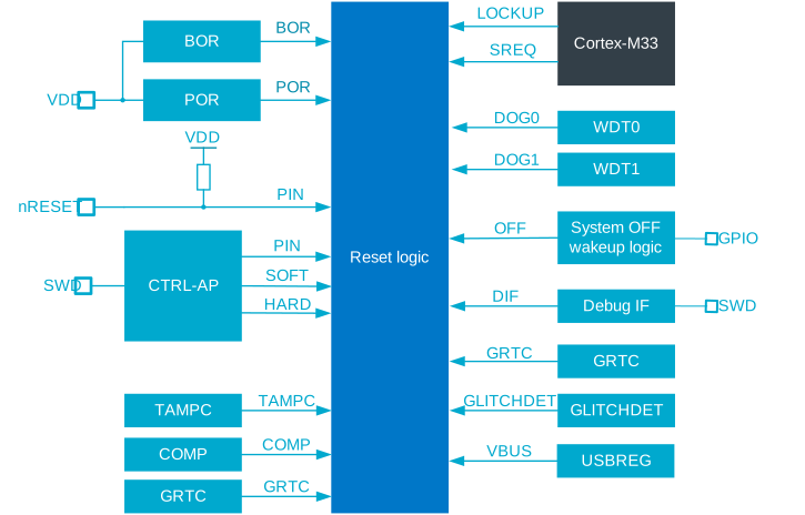
After a reset, the device automatically starts up. The register RESETREAS can be read to determine which source generated the reset.
Power-on reset
The power-on reset (POR) generator initializes the system when the supply voltage is above the power-on threshold.
The system is held in a reset state until the supply reaches the minimum operating voltage and the internal voltage regulators start. After a power-on reset, the device starts up.
Pin reset
A pin reset is generated when the physical reset pin on the device is asserted.
Pin reset is available on the reset pin nRESET, see Pin assignments. The device starts after nRESET is deasserted.
The reset pin has an internal pull-up resistor with the same resistance as GPIO pull-ups, see GPIO Electrical Specification.
CTRL-AP can also reset a pin, see CTRL-AP resets.
Brownout reset
The brownout reset (BOR) generator puts the system in RESET state if the supply voltage drops below the brownout reset threshold.
Similar to a power-on reset, the device starts after BOR is deasserted.
Glitch detector
The glitch detector (GLITCHDET) sets the system to the RESET state when the supply voltage or the device internal digital voltage drops below safe thresholds.
Similar to a power-on reset and a brownout reset, the device starts after GLITCHDET is deasserted.
For more information about the glitch detector, see GLITCHDET — Voltage glitch detectors.
Wakeup from System OFF mode reset
The device is reset when it wakes up from System OFF mode.
Similar to a power-on reset (POR), the device is started after waking up from System OFF.
If the device is in Debug interface mode, the debug access port (DAP) is not reset after a wakeup from System OFF mode. For more information, see Debug and trace.
For details on the System OFF mode, see System OFF mode.
Soft reset
A soft reset is generated when the SYSRESETREQ bit of the application interrupt and reset control register (AIRCR) in the Arm® CPU is set. For more information, see Arm documentation.
A soft reset can also be generated using CTRL-AP, see CTRL-AP resets.
Similar to a power-on reset (POR), the device is restarted after a soft reset.
CTRL-AP resets
CTRL-AP can generate the following resets.
- Soft reset
- Pin reset
- Hard reset. This is used during an Erase ALL operation and is less intrusive than Pin reset. For more details, see Reset behavior.
Through the debugger interface, CTRL-AP can generate three resets using register RESET. For more details, see CTRL-AP — Control access port.
Similar to a power-on reset (POR), the device is restarted after a CTRL-AP reset.
Watchdog timer reset
A watchdog timer (WDT) reset is generated when the watchdog timer times out.
Similar to a power-on reset (POR), the device is started after a watchdog reset.
Retained registers
A retained register is one that will retain its value in System OFF mode and through a reset, depending on the reset source. See the individual peripheral chapters for information on which of their registers are retained.
Reset behavior
The reset source determines the behavior of the device after a reset.
In System OFF mode, the watchdog timer is not running and CPU lockup is not possible. RAM may be fully or partially retained, depending on RAM retention settings in MEMCONF — Memory configuration.
If the device is in Debug Interface mode, the debug components are not reset. Additionally, CPU lockup does not generate a reset. See Debug and trace for more information about the different debug components in the system.
An 'x' in the table means that the specific module or register is reset. The table also explicitly lists which reset sources are commonly referred to as 'cold boot'.
| Retained registers | |||||||||||
|---|---|---|---|---|---|---|---|---|---|---|---|
| Reset source | Cold boot | CM33 | Peripherals | Debug | RAM | WDT | REGULATORS, OSCILLATORS and CPU speed | RESETREAS | POWER.GPRETREG | GPIO | GRTC. SYSCOUNTER |
| CPU lockup | x | x | x1 | x | |||||||
| Soft reset and CTRL-AP soft reset | x | x | x1 | ||||||||
| Wakeup from System Off mode | x | x | x | x | |||||||
| CTRL-AP hard reset | x | x | x | x | x | x | x | x | |||
| CTRL-AP pin reset | x | x | x | x | x | x | x | x | |||
| Watchdog timer reset | x | x | x | x | x | x | x | x | |||
| Pin reset | x | x | x | x | x | x | x | x | |||
| TAMPC reset | x | x | x | x | x | x | x | x | |||
| GLITCHDET reset | x | x | x | x | x | x | x | x | x | x | x |
| Brownout reset | x | x | x | x | x | x | x | x | x | x | x |
| Power-on reset | x | x | x | x | x | x | x | x | x | x | x |
1Except the CTRLSEL field.
For TAMPC reset sources, see TAMPC — Tamper controller.
Registers
Instances
| Instance | Domain | Base address | TrustZone | Split access | Description | ||
|---|---|---|---|---|---|---|---|
| Map | Att | DMA | |||||
RESET : S | GLOBAL | 0x5010E000 | US | S | NA | No | Reset status |
Register overview
| Register | Offset | TZ | Description |
|---|---|---|---|
| RESETREAS | 0x600 | Reset reason |
RESETREAS
Address offset: 0x600
Reset reason
Before entering System OFF mode, the RESETREAS register must be cleared.
| Bit number | 31 | 30 | 29 | 28 | 27 | 26 | 25 | 24 | 23 | 22 | 21 | 20 | 19 | 18 | 17 | 16 | 15 | 14 | 13 | 12 | 11 | 10 | 9 | 8 | 7 | 6 | 5 | 4 | 3 | 2 | 1 | 0 | |||
|---|---|---|---|---|---|---|---|---|---|---|---|---|---|---|---|---|---|---|---|---|---|---|---|---|---|---|---|---|---|---|---|---|---|---|---|
| ID | O | N | M | L | K | J | I | H | G | F | E | D | C | B | A | ||||||||||||||||||||
| Reset 0x00000000 | 0 | 0 | 0 | 0 | 0 | 0 | 0 | 0 | 0 | 0 | 0 | 0 | 0 | 0 | 0 | 0 | 0 | 0 | 0 | 0 | 0 | 0 | 0 | 0 | 0 | 0 | 0 | 0 | 0 | 0 | 0 | 0 | |||
| ID | R/W | Field | Value ID | Value | Description | ||||||||||||||||||||||||||||||
| A | RW | RESETPIN | Reset from pin reset detected CTRL-AP generating a pin reset has its own bit. | ||||||||||||||||||||||||||||||||
NotDetected | 0 | Not detected | |||||||||||||||||||||||||||||||||
Detected | 1 | Detected | |||||||||||||||||||||||||||||||||
| B | RW | DOG0 | Reset from watchdog timer 0 detected | ||||||||||||||||||||||||||||||||
NotDetected | 0 | Not detected | |||||||||||||||||||||||||||||||||
Detected | 1 | Detected | |||||||||||||||||||||||||||||||||
| C | RW | DOG1 | Reset from watchdog timer 1 detected | ||||||||||||||||||||||||||||||||
NotDetected | 0 | Not detected | |||||||||||||||||||||||||||||||||
Detected | 1 | Detected | |||||||||||||||||||||||||||||||||
| D | RW | CTRLAPSOFT | Soft reset from CTRL-AP detected | ||||||||||||||||||||||||||||||||
NotDetected | 0 | Not detected | |||||||||||||||||||||||||||||||||
Detected | 1 | Detected | |||||||||||||||||||||||||||||||||
| E | RW | CTRLAPHARD | Reset due to CTRL-AP hard reset | ||||||||||||||||||||||||||||||||
NotDetected | 0 | Not detected | |||||||||||||||||||||||||||||||||
Detected | 1 | Detected | |||||||||||||||||||||||||||||||||
| F | RW | CTRLAPPIN | Reset due to CTRL-AP pin reset | ||||||||||||||||||||||||||||||||
NotDetected | 0 | Not detected | |||||||||||||||||||||||||||||||||
Detected | 1 | Detected | |||||||||||||||||||||||||||||||||
| G | RW | SREQ | Reset from soft reset detected | ||||||||||||||||||||||||||||||||
NotDetected | 0 | Not detected | |||||||||||||||||||||||||||||||||
Detected | 1 | Detected | |||||||||||||||||||||||||||||||||
| H | RW | LOCKUP | Reset from CPU lockup detected | ||||||||||||||||||||||||||||||||
NotDetected | 0 | Not detected | |||||||||||||||||||||||||||||||||
Detected | 1 | Detected | |||||||||||||||||||||||||||||||||
| I | RW | OFF | Reset due to wakeup from System OFF mode when wakeup is triggered by DETECT signal from GPIO | ||||||||||||||||||||||||||||||||
NotDetected | 0 | Not detected | |||||||||||||||||||||||||||||||||
Detected | 1 | Detected | |||||||||||||||||||||||||||||||||
| J | RW | LPCOMP | Reset due to wakeup from System OFF mode when wakeup is triggered by ANADETECT signal from LPCOMP | ||||||||||||||||||||||||||||||||
NotDetected | 0 | Not detected | |||||||||||||||||||||||||||||||||
Detected | 1 | Detected | |||||||||||||||||||||||||||||||||
| K | RW | DIF | Reset triggered by Debug Interface | ||||||||||||||||||||||||||||||||
NotDetected | 0 | Not detected | |||||||||||||||||||||||||||||||||
Detected | 1 | Detected | |||||||||||||||||||||||||||||||||
| L | RW | GRTC | Reset due to wakeup from GRTC | ||||||||||||||||||||||||||||||||
NotDetected | 0 | Not detected | |||||||||||||||||||||||||||||||||
Detected | 1 | Detected | |||||||||||||||||||||||||||||||||
| M | RW | NFC | Reset after wakeup from System OFF mode due to NFC field being detected | ||||||||||||||||||||||||||||||||
NotDetected | 0 | Not detected | |||||||||||||||||||||||||||||||||
Detected | 1 | Detected | |||||||||||||||||||||||||||||||||
| N | RW | SECTAMPER | Reset due to illegal tampering of the device | ||||||||||||||||||||||||||||||||
NotDetected | 0 | Not detected | |||||||||||||||||||||||||||||||||
Detected | 1 | Detected | |||||||||||||||||||||||||||||||||
| O | RW | VBUS | Reset after wakeup from System OFF mode due to VBUS rising into valid range | ||||||||||||||||||||||||||||||||
NotDetected | 0 | Not detected | |||||||||||||||||||||||||||||||||
Detected | 1 | Detected | |||||||||||||||||||||||||||||||||