PPIB — PPI Bridge
PPIB connects tasks and events of peripherals in two different PPI systems in different power-domains.
A PPI system contains a number of peripherals that can communicate with each other by using tasks and events. This functionality is enabled by the DPPI peripheral. In a PPI system, the peripherals and DPPI are instantiated in the same APB bus.
The following figure shows a PPI system including a PPIB:
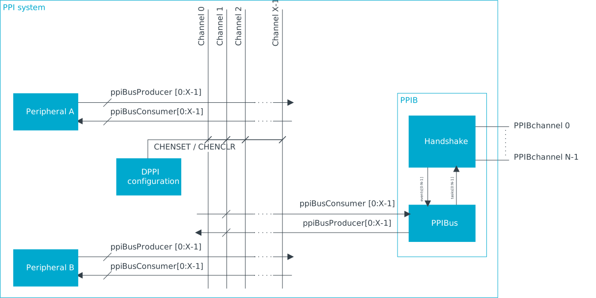
PPIB uses tasks and events like a standard peripheral, and connects to local DPPI channels via PPIBus. For more information on PPIBus module, see DPPI.
PPIB has a number of channels. Each PPIB channel connects to a single DPPI channel.
PPIB connections
A PPIB channel in one PPI system can be connected to a PPIB channel in another PPI system forming a PPIB connection.
A channel belonging to a PPIB instance in a PPI system is connected to a channel belonging to a PPIB instance in a different PPI system, creating a one-to-one PPIB connection between the two PPI systems. The connections are fixed and point-to-point, that is, a channel in a PPIB instance is connected only to a specific channel in another PPIB instance. For information on how the channels in the different PPIB instances are connected, see the Configuration table under the Registers section.
A PPIB channel can be configured as either source or sink. When configuring one side of the PPIB connection as source, the other side of the PPIB connection must be configured as sink, and viceversa. PPIB connections are unidirectional. Configuring both sides of a connection as source and sink at the same time will yield unexpected results.
On the source side of a PPIB connection, in order to send a (local) peripheral event to a different PPI system, the corresponding PPIB channel is configured as a consumer, subscribing to the same DPPI channel as the (local) peripheral publishes to, using the PPIB.SUBSCRIBE_SEND[n] register, with n the PPIB channel number.
On the sink side of a PPIB connection, for a (local) peripheral to be able to receive this event, the corresponding PPIB channel is configured as a producer, publishing to the same DPPI channel as the (local) peripheral subscribes to, using the PPIB.PUBLISH_RECEIVE[n] register, with n the PPIB channel number.
In a PPI system, several peripherals can publish to the same DPPI channel on the source side of a PPIB connection. Similarly, several peripherals can subscribe to the same DPPI channel on the sink side of a PPIB connection. This allows multiple connection options between peripherals in different PPI systems, same as DPPI allows in a local PPI system: one-to-one, one-to-many, many-to-one and many-to-many. However, when multiple peripherals can publish to the same DPPI channel on the source side of a PPIB connection, there is a risk of overflow. See Handshake and overflow.
Handshake and overflow
The two PPIB instances in a PPIB connection need a handshake to transfer a peripheral event.
This is handled by a Handshake module in the PPIB. If a handshake fails because an earlier event has not
been processed completely, the new event won't be sent. Instead, bit i in
OVERFLOW.SEND register on the source side will be set, with i
the correspoding PPIB channel number.
Connection examples
This section contains examples on how two connect two PPI systems using PPIB.
The following example shows how to create a PPIB connection between the TIMER10 compare event in the RADIO PD and the SAADC start task in PERI PD. PPIB11 in RADIO PD is hardwired to PPIB21 in PERI PD, which allows the PPI systems in the two separate power domains to connect. DPPI channel 0 is used by both power domains. Note that it is only necessary to use the same DPPI channel within the power domain; different DPPI channels can be used across power domains. An example of this is given further down in this section.
    // RADIO PD
    NRF_TIMER10->PUBLISH_COMPARE[0] = (0<<TIMER_PUBLISH_COMPARE_CHIDX_Pos) | TIMER_PUBLISH_COMPARE_EN_Msk;
    NRF_PPIB11->SUBSCRIBE_SEND[0] = (0<<PPIB_SUBSCRIBE_SEND_CHIDX_Pos) | PPIB_SUBSCRIBE_SEND_EN_Msk;
    NRF_DPPIC10->CHENSET = DPPIC_CHENSET_CH0_Msk;

    // PERI PD
    NRF_SAADC->SUBSCRIBE_START = (0<<SAADC_SUBSCRIBE_START_CHIDX_Pos) | SAADC_SUBSCRIBE_START_EN_Msk;
    NRF_PPIB21->PUBLISH_RECEIVE[0] = (0<<PPIB_PUBLISH_RECEIVE_CHIDX_Pos) | PPIB_PUBLISH_RECEIVE_EN_Msk;
    NRF_DPPIC20->CHENSET = DPPIC_CHENSET_CH0_Msk;
The following example shows how to create a PPIB connection between the TIMER10 compare event in the RADIO PD and the GPIOTE SET task in LP PD. The two PPI systems must be connected through PPIB instances PPIB21 and PPIB22 in PERI PD. These PPIB instances are not connected to any peripheral, only to the PPIB instances in RADIO and LP power domains. PERI PD acts as a central system that connects the two systems by means of local PPIB and DPPIC instances. This allows scaling to larger PPI systems, since multiple PPI systems can be interconnected through a central PPI system. DPPI channel 0 is used for internal RADIO PD connections, channel 1 is used by LP PD, and channel 5 is used by PERI PD. It is important that same DPPI channels are used within a power domain, but across domains the DPPI channel number does not matter.
    // RADIO PD
    NRF_TIMER10->PUBLISH_COMPARE[0] = (0<<TIMER_PUBLISH_COMPARE_CHIDX_Pos) | TIMER_PUBLISH_COMPARE_EN_Msk;
    NRF_PPIB11->SUBSCRIBE_SEND[0] = (0<<PPIB_SUBSCRIBE_SEND_CHIDX_Pos) | PPIB_SUBSCRIBE_SEND_EN_Msk;
    NRF_DPPIC10->CHENSET = DPPIC_CHENSET_CH0_Msk;

    // LP PD
    NRF_GPIOTE30->SUBSCRIBE_START = (1<<GPIOTE_SUBSCRIBE_SET_CHIDX_Pos) | GPIOTE_SUBSCRIBE_SET_EN_Msk;
    NRF_PPIB30->PUBLISH_RECEIVE[0] = (1<<PPIB_PUBLISH_RECEIVE_CHIDX_Pos) | PPIB_PUBLISH_RECEIVE_EN_Msk;
    NRF_DPPIC30->CHENSET = DPPIC_CHENSET_CH1_Msk;

    // PERI PD
    NRF_PPIB21->PUBLISH_RECEIVE[0] = (5<<PPIB_PUBLISH_RECEIVE_CHIDX_Pos) | PPIB_PUBLISH_RECEIVE_EN_Msk;
    NRF_PPIB22->SUBSCRIBE_SEND[0] = (5<<PPIB_SUBSCRIBE_SEND_CHIDX_Pos) | PPIB_SUBSCRIBE_SEND_EN_Msk;
    NRF_DPPIC20->CHENSET = DPPIC_CHENSET_CH5_Msk;
Registers
Instances
| Instance | Domain | Base address | Description |
|---|---|---|---|
| PPIB00 | GLOBAL | 0x40044000 | PPI bridge PPIB00 |
| PPIB01 | GLOBAL | 0x40045000 | PPI bridge PPIB01 |
| PPIB10 | GLOBAL | 0x40083000 | PPI bridge PPIB10 |
| PPIB11 | GLOBAL | 0x40084000 | PPI bridge PPIB11 |
| PPIB20 | GLOBAL | 0x400C3000 | PPI bridge PPIB20 |
| PPIB21 | GLOBAL | 0x400C4000 | PPI bridge PPIB21 |
| PPIB22 | GLOBAL | 0x400C5000 | PPI bridge PPIB22 |
| PPIB30 | GLOBAL | 0x40103000 | PPI bridge PPIB30 |
Configuration
| Instance | Domain | Configuration |
|---|---|---|
| PPIB00 | GLOBAL | Bridges PPI channels 0-11 between PPIB_00 (MCU) and PPIB_10 (RADIO) |
| PPIB01 | GLOBAL | Bridges PPI channels 0-7 between PPIB_01 (MCU) and PPIB_20 (PERI) |
| PPIB10 | GLOBAL | Bridges PPI channels 0-11 between PPIB_10 (RADIO) and PPIB_00 (MCU) |
| PPIB11 | GLOBAL | Bridges PPI channels 0-15 between PPIB_11 (RADIO) and PPIB_21 (PERI) |
| PPIB20 | GLOBAL | Bridges PPI channels 0-7 between PPIB_20 (PERI) and PPIB_01 (MCU) |
| PPIB21 | GLOBAL | Bridges PPI channels 0-15 between PPIB_21 (PERI) and PPIB_11 (RADIO) |
| PPIB22 | GLOBAL | Bridges PPI channels 0-3 between PPIB_22 (PERI) and PPIB_30 (LP) |
| PPIB30 | GLOBAL | Bridges PPI channels 0-3 between PPIB_30 (LP) and PPIB_22 (PERI) |
Register overview
| Register | Offset | Description |
|---|---|---|
| TASKS_SEND[n] | 0x000 | This task is unused, but the PPIB provides the SUBSCRIBE task to connect SEND [n] task. |
| SUBSCRIBE_SEND[n] | 0x080 | Subscribe configuration for task SEND[n] |
| EVENTS_RECEIVE[n] | 0x100 | This event is unused, but the PPIB provides the PUBLISH event to connect RECEIVE [n] event. |
| PUBLISH_RECEIVE[n] | 0x180 | Publish configuration for event RECEIVE[n] |
| OVERFLOW.SEND | 0x400 | The task overflow for SEND tasks using SUBSCRIBE_SEND. Write 0 to clear. |
TASKS_SEND[n]
Address offset: 0x000 + (n × 0x4)
This task is unused, but the PPIB provides the SUBSCRIBE task to connect SEND [n] task.
Writes to SEND [n] task are ignored.
| Bit number | 31 | 30 | 29 | 28 | 27 | 26 | 25 | 24 | 23 | 22 | 21 | 20 | 19 | 18 | 17 | 16 | 15 | 14 | 13 | 12 | 11 | 10 | 9 | 8 | 7 | 6 | 5 | 4 | 3 | 2 | 1 | 0 | |||
|---|---|---|---|---|---|---|---|---|---|---|---|---|---|---|---|---|---|---|---|---|---|---|---|---|---|---|---|---|---|---|---|---|---|---|---|
| ID | A | ||||||||||||||||||||||||||||||||||
| Reset 0x00000000 | 0 | 0 | 0 | 0 | 0 | 0 | 0 | 0 | 0 | 0 | 0 | 0 | 0 | 0 | 0 | 0 | 0 | 0 | 0 | 0 | 0 | 0 | 0 | 0 | 0 | 0 | 0 | 0 | 0 | 0 | 0 | 0 | |||
| ID | R/W | Field | Value ID | Value | Description | ||||||||||||||||||||||||||||||
| A | W | TASKS_SEND | This task is unused, but the PPIB provides the SUBSCRIBE task to connect SEND [n] task. Writes to SEND [n] task are ignored. | ||||||||||||||||||||||||||||||||
Trigger | 1 | Trigger task | |||||||||||||||||||||||||||||||||
SUBSCRIBE_SEND[n]
Address offset: 0x080 + (n × 0x4)
Subscribe configuration for task SEND[n]
Writes to SEND [n] task are ignored.
| Bit number | 31 | 30 | 29 | 28 | 27 | 26 | 25 | 24 | 23 | 22 | 21 | 20 | 19 | 18 | 17 | 16 | 15 | 14 | 13 | 12 | 11 | 10 | 9 | 8 | 7 | 6 | 5 | 4 | 3 | 2 | 1 | 0 | |||
|---|---|---|---|---|---|---|---|---|---|---|---|---|---|---|---|---|---|---|---|---|---|---|---|---|---|---|---|---|---|---|---|---|---|---|---|
| ID | B | A | A | A | A | A | A | A | A | ||||||||||||||||||||||||||
| Reset 0x00000000 | 0 | 0 | 0 | 0 | 0 | 0 | 0 | 0 | 0 | 0 | 0 | 0 | 0 | 0 | 0 | 0 | 0 | 0 | 0 | 0 | 0 | 0 | 0 | 0 | 0 | 0 | 0 | 0 | 0 | 0 | 0 | 0 | |||
| ID | R/W | Field | Value ID | Value | Description | ||||||||||||||||||||||||||||||
| A | RW | CHIDX | [0..255] | DPPI channel that task SEND[n] will subscribe to | |||||||||||||||||||||||||||||||
| B | RW | EN | |||||||||||||||||||||||||||||||||
Disabled | 0 | Disable subscription | |||||||||||||||||||||||||||||||||
Enabled | 1 | Enable subscription | |||||||||||||||||||||||||||||||||
EVENTS_RECEIVE[n]
Address offset: 0x100 + (n × 0x4)
This event is unused, but the PPIB provides the PUBLISH event to connect RECEIVE [n] event.
| Bit number | 31 | 30 | 29 | 28 | 27 | 26 | 25 | 24 | 23 | 22 | 21 | 20 | 19 | 18 | 17 | 16 | 15 | 14 | 13 | 12 | 11 | 10 | 9 | 8 | 7 | 6 | 5 | 4 | 3 | 2 | 1 | 0 | |||
|---|---|---|---|---|---|---|---|---|---|---|---|---|---|---|---|---|---|---|---|---|---|---|---|---|---|---|---|---|---|---|---|---|---|---|---|
| ID | A | ||||||||||||||||||||||||||||||||||
| Reset 0x00000000 | 0 | 0 | 0 | 0 | 0 | 0 | 0 | 0 | 0 | 0 | 0 | 0 | 0 | 0 | 0 | 0 | 0 | 0 | 0 | 0 | 0 | 0 | 0 | 0 | 0 | 0 | 0 | 0 | 0 | 0 | 0 | 0 | |||
| ID | R/W | Field | Value ID | Value | Description | ||||||||||||||||||||||||||||||
| A | RW | EVENTS_RECEIVE | This event is unused, but the PPIB provides the PUBLISH event to connect RECEIVE [n] event. | ||||||||||||||||||||||||||||||||
NotGenerated | 0 | Event not generated | |||||||||||||||||||||||||||||||||
Generated | 1 | Event generated | |||||||||||||||||||||||||||||||||
PUBLISH_RECEIVE[n]
Address offset: 0x180 + (n × 0x4)
Publish configuration for event RECEIVE[n]
| Bit number | 31 | 30 | 29 | 28 | 27 | 26 | 25 | 24 | 23 | 22 | 21 | 20 | 19 | 18 | 17 | 16 | 15 | 14 | 13 | 12 | 11 | 10 | 9 | 8 | 7 | 6 | 5 | 4 | 3 | 2 | 1 | 0 | |||
|---|---|---|---|---|---|---|---|---|---|---|---|---|---|---|---|---|---|---|---|---|---|---|---|---|---|---|---|---|---|---|---|---|---|---|---|
| ID | B | A | A | A | A | A | A | A | A | ||||||||||||||||||||||||||
| Reset 0x00000000 | 0 | 0 | 0 | 0 | 0 | 0 | 0 | 0 | 0 | 0 | 0 | 0 | 0 | 0 | 0 | 0 | 0 | 0 | 0 | 0 | 0 | 0 | 0 | 0 | 0 | 0 | 0 | 0 | 0 | 0 | 0 | 0 | |||
| ID | R/W | Field | Value ID | Value | Description | ||||||||||||||||||||||||||||||
| A | RW | CHIDX | [0..255] | DPPI channel that event RECEIVE[n] will publish to | |||||||||||||||||||||||||||||||
| B | RW | EN | |||||||||||||||||||||||||||||||||
Disabled | 0 | Disable publishing | |||||||||||||||||||||||||||||||||
Enabled | 1 | Enable publishing | |||||||||||||||||||||||||||||||||
OVERFLOW.SEND
Address offset: 0x400
The task overflow for SEND tasks using SUBSCRIBE_SEND.
Write 0 to clear.
| Bit number | 31 | 30 | 29 | 28 | 27 | 26 | 25 | 24 | 23 | 22 | 21 | 20 | 19 | 18 | 17 | 16 | 15 | 14 | 13 | 12 | 11 | 10 | 9 | 8 | 7 | 6 | 5 | 4 | 3 | 2 | 1 | 0 | |||
|---|---|---|---|---|---|---|---|---|---|---|---|---|---|---|---|---|---|---|---|---|---|---|---|---|---|---|---|---|---|---|---|---|---|---|---|
| ID | f | e | d | c | b | a | Z | Y | X | W | V | U | T | S | R | Q | P | O | N | M | L | K | J | I | H | G | F | E | D | C | B | A | |||
| Reset 0x00000000 | 0 | 0 | 0 | 0 | 0 | 0 | 0 | 0 | 0 | 0 | 0 | 0 | 0 | 0 | 0 | 0 | 0 | 0 | 0 | 0 | 0 | 0 | 0 | 0 | 0 | 0 | 0 | 0 | 0 | 0 | 0 | 0 | |||
| ID | R/W | Field | Value ID | Value | Description | ||||||||||||||||||||||||||||||
| A-f | RW | SEND[i] (i=0..31) | The status for tasks overflow at SUBSCRIBE_SEND[i]. | ||||||||||||||||||||||||||||||||
Overflow | 1 | Task overflow is happened. | |||||||||||||||||||||||||||||||||
NoOverflow | 0 | Task overflow is not happened. | |||||||||||||||||||||||||||||||||