CRACEN TRNG — True Random Number Generator
The CRACEN TRNG provides true random number generation using the CRACEN peripheral, with only the random number generator functionality enabled.
To use the CRACEN TRNG, the CRACEN peripheral must first be configured.
After a reset, the TRNG function is disabled by default. Enable it by writing to the ENABLE register.
Once the TRNG is enabled through the CRACEN peripheral, configure and activate it using the RNGCONTROL.CONTROL register to begin random number generation.
Random Number Generator
The NIST-800-90B non-deterministic, true random number generator, can be used by cryptographic modules as an entropy source.
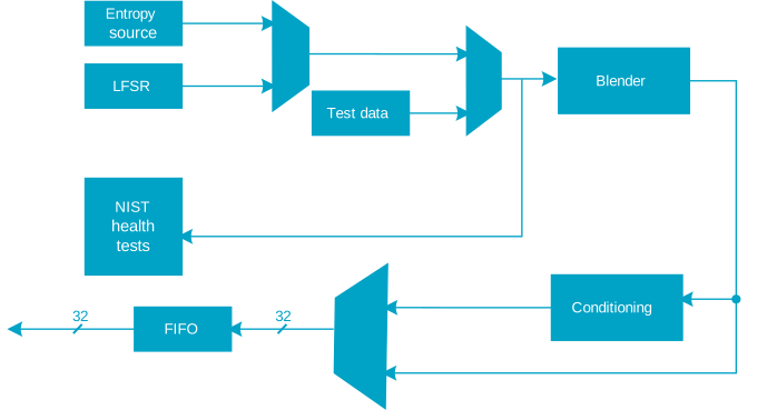
Entropy Source
The entropy source is a set of distinct oscillator rings, where each ring is composed of an odd number of inverters and oscillates at a much higher frequency than the digital sampling frequency. The analog signal from all rings is converted into a digital signal by sampling it at a regular clock frequency.
It is possible to observe the samples from this noise source by bypassing the conditioning function (by setting the bit CONTROL.CONDBYPASS to 1).
Blender
There are 4 shares (sets) of 8 distinct ring oscillators. The output bitstream from each set has its own set of tests as described in Continuous Testing. These bitstreams are merged by a blender to produce a single stream of entropy.
The most efficient way to generate random data with minimal latency is to concatenate the ring oscillator output streams (the hardware default). However, these outputs can be blended to increase entropy. The blender can be configured to use different methods for entropy enhancement via the BLENDINGMETHOD field. XORLEVEL1 reduces 4×8 bits to 4 bits, while XORLEVEL2 further reduces the 4 bits to 1. Another blending option is the Von-Neumann debiasing algorithm (VONNEUMANN), which assumes the input bits are independent and identically distributed (IID), producing a likely uniform output. When the Von-Neumann debiasing method is selected, the XORLEVEL1 and XORLEVEL2 compression methods are applied first, then 00 and 11 bit pairs are discarded while 10 and 01 pairs are retained, with only the first bit of each retained pair being output.
Sampling Process
When the output node of a high frequency ring oscillator (RO) is sampled at the rate of a low-frequency clock, then the sampled bit is random. The device ensures that Tosc >> TRO, where Tosc is the duration during which the ring oscillator is free-running.
Two oscillation modes are supported: warm mode and cold mode.


Note that in reality DOSC is typically larger than what is suggested by the above figures, ensuring that TOSC >> TRST.
Warm mode could theoretically exhibit temporal correlations, unlike cold mode, which is rendered memoryless by resetting to a predefined state before each random data generation. To mitigate this in warm mode, an additional margin can be applied to TOSC, by using the SAMPLINGPERIOD register. Health tests will activate if issues arise.
Cold mode may be more susceptible to side-channel attacks, as the cessation of oscillation offers a synchronization point, potentially allowing an attacker to more readily determine when samples are generated. Warm mode is not entirely immune to such vulnerabilities either, because the AES can produce a power signature that also serves as a synchronization point.
The warm mode will have a better throughput.
The choice between the two options depends on the application requirements. Both approaches are valid and pass the relevant test suites .
Continuous Testing
The samples from entropy source are monitored permanently by repetition and proportion tests running in parallel. Tests are run on the raw samples, i.e. not influenced by the CONTROL.BLENDINGMETHOD setting. Optionally, correlation and auto-correlation tests can be used as well.
Repetition Count Test
The repetition count test as described in section 4.4.1 of NIST Special Publication 800-90 is implemented. The acceptable false-positive rate defaults to α = 2-20.
For a min-entropy of H=8.0, the default repetition cut-off value (REPEATTHRESHOLD) is 4. Test can be disabled via DISREPETTESTS bit in the CONTROL register. Failures in the repetition test for each share are reported in the REPTESTFAILPERSHARE bits in the STATUS register.
Adaptive Proportion Test
The proportion count test as described in section 4.4.2 of NIST Special Publication 800-90 has been implemented with a window size of W = 512 non-binary samples. The acceptable false-positive rate has been fixed to α = 2-20. The entropy source delivers 1-bit sample and after chosen blending method non-binary samples are created. For a min-entropy of H=8.0, default proportion cut-off value is C = 1+CRITBINOM(W, 2-H,1-α) = 13. Cut-off value is programmed in PROPTESTCUTOFF register. This test can be disabled via CONTROL.DISPROPTESTS. Failing per share proportion test is reported via STATUS.PROPTESTFAILPERSHARE.
NIST-800-90B Start-up Test
Compliant with NIST-800-90B, the Repetition Count Test and the Adaptive Proportion Test are required to pass before any data is read from the FIFO.
Correlation Count Test
When two ring oscillators are coupled through injection locking, their bitstreams become correlated. Correlation count test can detect this occurrence. It uses time-division multiplexing and even single pair of ring oscillators case is supported. Window size of W = 128 samples is used with cut-off values defined in CORRTESTCUTOFF registers. Specific delay checks (or all checks) can be disabled via CONTROL.DISCORRTESTS.
Autocorrelation Count Test
When a ring oscillator is continuously sampled without accumulating enough jitter, the produced bitstream shows periodic behavior. Autocorrelation count test is able to detect this behavior. It uses time-division multiplexing and even single ring oscillator case is supported. Window size of W = 128 samples is used with cut-off values defined as in AUTOCORRTESTCUTOFF registers. Specific delay checks (or all checks) can be disabled via CONTROL.DISAUTOCORRTESTS.
Conditioning
The CBC-MAC mode (as described in section 3.1.5.1.1 and Appendix F in NIST Special Publication 800-90) of AES128 has been used as FIPS-approved keyed conditioning function. The conditioning function takes CONTROL.NB128BITBLOCKS x 128 bits from the entropy source as input and generates 128 bits as output. Assuming a min-entropy of 50% and NB128BITBLOCKS = 4, the input entropy is hin=512 x 50%=256 bits. According to section 3.1.5.1.2 in NIST Special Publication 800-90, the output of the conditioning function can be considered to have 128 bits of full entropy. The conditioning function can be tested by sending known data (using TESTDATA with CONTROL.TESTEN=1).
FIFO
The output entropy is split into 32-bit words and stored in the output FIFO. The FIFO size in 32-bit words can be read from the FIFODEPTH register. The FIFO operates as a single word stream - the first available word is returned regardless of which FIFO entry is accessed. When a word is read from the FIFO, the FIFOLEVEL register automatically decreases to reflect the number of remaining 32-bit random numbers. The FIFOTHRESHOLD register determines when the RNG state machine starts refilling the FIFO.
Depending on the configuration of the conditioning function, either raw noise samples or conditioned samples are written to the FIFO when the ENABLE bit is set. For details on the state machine that manages the filling of the FIFO, see Control FSM state diagram . If the CONTROL.FIFOWRITESTARTUP bit is set, the statemachine will start filling the FIFO immediately after the FIFO is enabled, ignoring startup failures. If the CONTROL.IGNOREHEALTHTESTSFAILFORFSM bit is set the state machine ignores all the health test failures and allows data to be written to the FIFO even if health tests fail. It is not recommended to set either of these bits, as it may lead to the FIFO being filled with data of poor quality.
When deviating from recommended hardware settings, it is the user's responsibility to verify the validity of the data in the FIFO.
Control FSM
The RNG is controlled by an finite state machine (FSM) which handles all the low-level interactions between the different hardware components described in Random number generator block diagram . During normal operation the FSM ensures that the entropy source is controlled in a NIST-800-90B compatible way, as shown in the following figure.
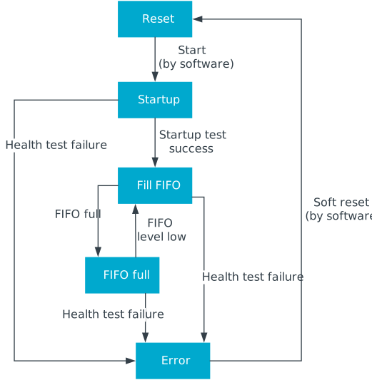
The state diagram does not show that asserting the hard or soft resets and/or de-asserting the enable bit cause the state to be reset to "Reset".
Check the Conditioning Function
- Apply software reset (RNGCONTROL.CONTROL.SOFTRST = 1)
- Write the control register
- Write the KEY register
- Write the data to the TESTDATA register (after each write, wait until the TESTDATABUSY flag becomes low)
- Read the result from the FIFO
The table below shows an example of data (taken from section F.2.1 in NIST Special Publication 800-38A)
| 128-bit format | 32-bit APB format | |
|---|---|---|
| Key | 0x2B7E151628AED2A6ABF7158809CF4F3C | 0x16157E2B 0xA6D2AE28 0x8815F7AB 0x3C4FCF09 |
| Input | 0x6BC0BCE12A459991E134741A7F9E1925 | 0xE1BCC06B 0x9199452A 0x1A7434E1 0x25199E7F |
| 0xAE2D8A571E03AC9C9EB76FAC45AF8E51 | 0x578A2DAE 0x9CAC031E 0xAC6FB79E 0x518EAF45 | |
| 0x30C81C46A35CE411E5FBC1191A0A52EF | 0x461CC830 0x11E45CA3 0x19C1FBE5 0xEF520A1A | |
| 0xF69F2445DF4F9B17AD2B417BE66C3710 | 0x45249FF6 0x179B4FDF 0x7B412BAD 0x10376CE6 | |
| Expected output | 0x3FF1CAA1681FAC09120ECA307586E1A7 | 0xA1CAF13F 0x09AC1F68 0x30CA0E12 0xA7E18675 |
Check the entropy source
- Apply software reset
- Write the CONTROL register ensuring that none of the health tests are bypassed and set the ENABLE bit.
- Wait until the STATE is not Reset, Startup or Error. When this is the case, all start-up tests have passed and the entropy source is working correctly.
- If the state is Error, select different values for SAMPLINGPERIOD and WARMUPPERIOD and go back to 1.
Program the Key
- Check the FIFOLEVEL register to monitor the amount of generated random numbers or wait for the FULLINT IRQ.
- When FIFOLEVEL has reached the expected value or when an IRQ has been received, read the random numbers from the FIFO.
- Use 4 x 32-bit random values to program a random key in the KEY register.
- Apply software reset to flush the FIFO. By toggling the SOFTRST bit in the CONTROL register.
Get Samples
Change Configuration
Data Format - Byte Ordering
All cryptographic data are handled following the big-endian format (AES standard). That means that the first byte (lowest address) of the data is the Most Significant Byte (MSB).
The APB bus uses little endian format. That means that the Least Significant Byte (LSB) is stored at the lowest address.
For example, a 128-bit block D[A] = 0x00112233445566778899AABBCCDDEEFF stored at address A (multiple of 4) appears on APB bus as the following 32-bit words:
- D[A+0] = 0x33221100
- D[A+4] = 0x77665544
- D[A+8] = 0xBBAA9988
- D[A+12] = 0xFFDDEEC
Performance
When conditioning is enabled, the number of cycles required for the RNG to generate the first N words of data can be estimated with the following formula:
Nbcycles ≈ C + 1024 * (SAMPLINGPERIOD + COOLDOWNPERIOD) + 128 * NB128BITBLOCKS * max(1/8, (SAMPLINGPERIOD + COOLDOWNPERIOD + 1) * BLENDING_RATIO / 128) * max(0, N - 4) + WARMUPPERIOD
where C is the number of cycles required to initialize the RNG state machine.
BLENDING_RATIO is the ratio of bit reduction due to the chosen BLENDINGMETHOD (1 for CONCATENATION, 8 for XORLEVEL1, 32 for XORLEVEL2, and 128 for VONNEUMANN).
Interrupt
To enable the RNG interrupt, enable the RNG field in the CRACEN.INTEN register and set the necessary INTEN bits in the CRACENCORE.RNGCONTROL.CONTROL register.
The RNG has two interrupt causes:
- FULLINT: set when the FIFO becomes full. It can be cleared when FIFO is no longer full by writing to the FIFOLEVEL register or activating soft-reset.
- ANYHEALTHTESTFAIL: set when an error is detected in any of the health tests. It is cleared when writing a zero to the corresponding bit in the status register or when the soft-reset is activated.
For each interrupt, there is a status bit in the STATUS register and an enable bit in the CONTROL register. The STATUS register state does not depend on the interrupt enable bits in the control register. The interrupt enable bits are only used to control the generation of the event CRACEN.EVENTS_RNG and the signal to the interrupt handler.
Registers
Instances
| Instance | Domain | Base address | Description |
|---|---|---|---|
| CRACEN | GLOBAL | 0x40059000 | True Random Number Generator |
Register overview
| Register | Offset | Description |
|---|---|---|
| EVENTS_RNG | 0x104 | Event indicating that interrupt triggered at RNG |
| INTEN | 0x300 | Enable or disable interrupt |
| INTENSET | 0x304 | Enable interrupt |
| INTENCLR | 0x308 | Disable interrupt |
| INTPEND | 0x30C | Pending interrupts |
| ENABLE | 0x400 | Enable RNG peripheral module. |
EVENTS_RNG
Address offset: 0x104
Event indicating that interrupt triggered at RNG
The interrupt source must be cleared at RNG before clearing this event.
| Bit number | 31 | 30 | 29 | 28 | 27 | 26 | 25 | 24 | 23 | 22 | 21 | 20 | 19 | 18 | 17 | 16 | 15 | 14 | 13 | 12 | 11 | 10 | 9 | 8 | 7 | 6 | 5 | 4 | 3 | 2 | 1 | 0 | |||
|---|---|---|---|---|---|---|---|---|---|---|---|---|---|---|---|---|---|---|---|---|---|---|---|---|---|---|---|---|---|---|---|---|---|---|---|
| ID | A | ||||||||||||||||||||||||||||||||||
| Reset 0x00000000 | 0 | 0 | 0 | 0 | 0 | 0 | 0 | 0 | 0 | 0 | 0 | 0 | 0 | 0 | 0 | 0 | 0 | 0 | 0 | 0 | 0 | 0 | 0 | 0 | 0 | 0 | 0 | 0 | 0 | 0 | 0 | 0 | |||
| ID | R/W | Field | Value ID | Value | Description | ||||||||||||||||||||||||||||||
| A | RW | EVENTS_RNG | Event indicating that interrupt triggered at RNG The interrupt source must be cleared at RNG before clearing this event. | ||||||||||||||||||||||||||||||||
NotGenerated | 0 | Event not generated | |||||||||||||||||||||||||||||||||
Generated | 1 | Event generated | |||||||||||||||||||||||||||||||||
INTEN
Address offset: 0x300
Enable or disable interrupt
| Bit number | 31 | 30 | 29 | 28 | 27 | 26 | 25 | 24 | 23 | 22 | 21 | 20 | 19 | 18 | 17 | 16 | 15 | 14 | 13 | 12 | 11 | 10 | 9 | 8 | 7 | 6 | 5 | 4 | 3 | 2 | 1 | 0 | |||
|---|---|---|---|---|---|---|---|---|---|---|---|---|---|---|---|---|---|---|---|---|---|---|---|---|---|---|---|---|---|---|---|---|---|---|---|
| ID | A | ||||||||||||||||||||||||||||||||||
| Reset 0x00000000 | 0 | 0 | 0 | 0 | 0 | 0 | 0 | 0 | 0 | 0 | 0 | 0 | 0 | 0 | 0 | 0 | 0 | 0 | 0 | 0 | 0 | 0 | 0 | 0 | 0 | 0 | 0 | 0 | 0 | 0 | 0 | 0 | |||
| ID | R/W | Field | Value ID | Value | Description | ||||||||||||||||||||||||||||||
| A | RW | RNG | Enable or disable interrupt for event RNG The interrupt source must be cleared at RNG before clearing this event. | ||||||||||||||||||||||||||||||||
Disabled | 0 | Disable | |||||||||||||||||||||||||||||||||
Enabled | 1 | Enable | |||||||||||||||||||||||||||||||||
INTENSET
Address offset: 0x304
Enable interrupt
| Bit number | 31 | 30 | 29 | 28 | 27 | 26 | 25 | 24 | 23 | 22 | 21 | 20 | 19 | 18 | 17 | 16 | 15 | 14 | 13 | 12 | 11 | 10 | 9 | 8 | 7 | 6 | 5 | 4 | 3 | 2 | 1 | 0 | |||
|---|---|---|---|---|---|---|---|---|---|---|---|---|---|---|---|---|---|---|---|---|---|---|---|---|---|---|---|---|---|---|---|---|---|---|---|
| ID | A | ||||||||||||||||||||||||||||||||||
| Reset 0x00000000 | 0 | 0 | 0 | 0 | 0 | 0 | 0 | 0 | 0 | 0 | 0 | 0 | 0 | 0 | 0 | 0 | 0 | 0 | 0 | 0 | 0 | 0 | 0 | 0 | 0 | 0 | 0 | 0 | 0 | 0 | 0 | 0 | |||
| ID | R/W | Field | Value ID | Value | Description | ||||||||||||||||||||||||||||||
| A | RW | RNG | Write '1' to enable interrupt for event RNG The interrupt source must be cleared at RNG before clearing this event. | ||||||||||||||||||||||||||||||||
Set | 1 | Enable | |||||||||||||||||||||||||||||||||
Disabled | 0 | Read: Disabled | |||||||||||||||||||||||||||||||||
Enabled | 1 | Read: Enabled | |||||||||||||||||||||||||||||||||
INTENCLR
Address offset: 0x308
Disable interrupt
| Bit number | 31 | 30 | 29 | 28 | 27 | 26 | 25 | 24 | 23 | 22 | 21 | 20 | 19 | 18 | 17 | 16 | 15 | 14 | 13 | 12 | 11 | 10 | 9 | 8 | 7 | 6 | 5 | 4 | 3 | 2 | 1 | 0 | |||
|---|---|---|---|---|---|---|---|---|---|---|---|---|---|---|---|---|---|---|---|---|---|---|---|---|---|---|---|---|---|---|---|---|---|---|---|
| ID | A | ||||||||||||||||||||||||||||||||||
| Reset 0x00000000 | 0 | 0 | 0 | 0 | 0 | 0 | 0 | 0 | 0 | 0 | 0 | 0 | 0 | 0 | 0 | 0 | 0 | 0 | 0 | 0 | 0 | 0 | 0 | 0 | 0 | 0 | 0 | 0 | 0 | 0 | 0 | 0 | |||
| ID | R/W | Field | Value ID | Value | Description | ||||||||||||||||||||||||||||||
| A | RW | RNG | Write '1' to disable interrupt for event RNG The interrupt source must be cleared at RNG before clearing this event. | ||||||||||||||||||||||||||||||||
Clear | 1 | Disable | |||||||||||||||||||||||||||||||||
Disabled | 0 | Read: Disabled | |||||||||||||||||||||||||||||||||
Enabled | 1 | Read: Enabled | |||||||||||||||||||||||||||||||||
INTPEND
Address offset: 0x30C
Pending interrupts
| Bit number | 31 | 30 | 29 | 28 | 27 | 26 | 25 | 24 | 23 | 22 | 21 | 20 | 19 | 18 | 17 | 16 | 15 | 14 | 13 | 12 | 11 | 10 | 9 | 8 | 7 | 6 | 5 | 4 | 3 | 2 | 1 | 0 | |||
|---|---|---|---|---|---|---|---|---|---|---|---|---|---|---|---|---|---|---|---|---|---|---|---|---|---|---|---|---|---|---|---|---|---|---|---|
| ID | A | ||||||||||||||||||||||||||||||||||
| Reset 0x00000000 | 0 | 0 | 0 | 0 | 0 | 0 | 0 | 0 | 0 | 0 | 0 | 0 | 0 | 0 | 0 | 0 | 0 | 0 | 0 | 0 | 0 | 0 | 0 | 0 | 0 | 0 | 0 | 0 | 0 | 0 | 0 | 0 | |||
| ID | R/W | Field | Value ID | Value | Description | ||||||||||||||||||||||||||||||
| A | R | RNG | Read pending status of interrupt for event RNG The interrupt source must be cleared at RNG before clearing this event. | ||||||||||||||||||||||||||||||||
NotPending | 0 | Read: Not pending | |||||||||||||||||||||||||||||||||
Pending | 1 | Read: Pending | |||||||||||||||||||||||||||||||||
ENABLE
Address offset: 0x400
Enable RNG peripheral module.
| Bit number | 31 | 30 | 29 | 28 | 27 | 26 | 25 | 24 | 23 | 22 | 21 | 20 | 19 | 18 | 17 | 16 | 15 | 14 | 13 | 12 | 11 | 10 | 9 | 8 | 7 | 6 | 5 | 4 | 3 | 2 | 1 | 0 | |||
|---|---|---|---|---|---|---|---|---|---|---|---|---|---|---|---|---|---|---|---|---|---|---|---|---|---|---|---|---|---|---|---|---|---|---|---|
| ID | A | ||||||||||||||||||||||||||||||||||
| Reset 0x00000000 | 0 | 0 | 0 | 0 | 0 | 0 | 0 | 0 | 0 | 0 | 0 | 0 | 0 | 0 | 0 | 0 | 0 | 0 | 0 | 0 | 0 | 0 | 0 | 0 | 0 | 0 | 0 | 0 | 0 | 0 | 0 | 0 | |||
| ID | R/W | Field | Value ID | Value | Description | ||||||||||||||||||||||||||||||
| A | RW | RNG | Enable RNG | ||||||||||||||||||||||||||||||||
Disabled | 0 | RNG disabled. | |||||||||||||||||||||||||||||||||
Enabled | 1 | RNG enabled. | |||||||||||||||||||||||||||||||||
Registers
Instances
| Instance | Domain | Base address | Description |
|---|---|---|---|
| CRACENCORE | GLOBAL | 0x40059000 | True Random Number Generator |
Configuration
| Instance | Domain | Configuration |
|---|---|---|
| CRACENCORE | GLOBAL | RNGCONTROL registers included |
Register overview
| Register | Offset | Description |
|---|---|---|
| RNGCONTROL.CONTROL | 0x500 | Control register |
| RNGCONTROL.FIFOLEVEL | 0x504 | FIFO level register. |
| RNGCONTROL.FIFOTHRESHOLD | 0x508 | FIFO threshold register. |
| RNGCONTROL.FIFODEPTH | 0x50C | FIFO depth register. |
| RNGCONTROL.KEY[n] | 0x510 | Key register. |
| RNGCONTROL.TESTDATA | 0x520 | Test data register. |
| RNGCONTROL.REPEATTHRESHOLD | 0x524 | Repetition test cut-off register. |
| RNGCONTROL.PROPTESTCUTOFF | 0x528 | Proportion test cut-off register. |
| RNGCONTROL.LFSRSEED | 0x52C | LFSR seed register. |
| RNGCONTROL.STATUS | 0x530 | Status register. |
| RNGCONTROL.WARMUPPERIOD | 0x534 | Number of clock cycles in warm-up sequence. |
| RNGCONTROL.DISABLEOSC | 0x538 | DisableOsc register. |
| RNGCONTROL.SAMPLINGPERIOD | 0x544 | Number of clock cycles between sampling moments. |
| RNGCONTROL.HWCONFIG | 0x558 | Hardware configuration register. |
| RNGCONTROL.COOLDOWNPERIOD | 0x55C | Number of clock cycles in cool-down sequence. |
| RNGCONTROL.AUTOCORRTESTCUTOFF0 | 0x560 | AutoCorrTestCutoff register 0 |
| RNGCONTROL.AUTOCORRTESTCUTOFF1 | 0x564 | AutoCorrTestCutoff register 1 |
| RNGCONTROL.CORRTESTCUTOFF0 | 0x568 | CorrTestCutoff register 0 |
| RNGCONTROL.CORRTESTCUTOFF1 | 0x56C | CorrTestCutoff register 1 |
| RNGCONTROL.AUTOCORRTESTFAILED | 0x570 | Auto-correlation test failing ring(s). |
| RNGCONTROL.CORRTESTFAILED | 0x574 | Correlation test failing ring. |
| RNGCONTROL.HWVERSION | 0x57C | Fixed to 1 for this version. |
| RNGCONTROL.FIFO[n] | 0x580 | FIFO data |
RNGCONTROL.CONTROL
Address offset: 0x500
Control register
| Bit number | 31 | 30 | 29 | 28 | 27 | 26 | 25 | 24 | 23 | 22 | 21 | 20 | 19 | 18 | 17 | 16 | 15 | 14 | 13 | 12 | 11 | 10 | 9 | 8 | 7 | 6 | 5 | 4 | 3 | 2 | 1 | 0 | |||
|---|---|---|---|---|---|---|---|---|---|---|---|---|---|---|---|---|---|---|---|---|---|---|---|---|---|---|---|---|---|---|---|---|---|---|---|
| ID | P | P | O | O | O | N | N | M | L | K | J | J | J | J | I | H | G | F | E | D | C | B | A | ||||||||||||
| Reset 0x00040000 | 0 | 0 | 0 | 0 | 0 | 0 | 0 | 0 | 0 | 0 | 0 | 0 | 0 | 1 | 0 | 0 | 0 | 0 | 0 | 0 | 0 | 0 | 0 | 0 | 0 | 0 | 0 | 0 | 0 | 0 | 0 | 0 | |||
| ID | R/W | Field | Value ID | Value | Description | ||||||||||||||||||||||||||||||
| A | W | ENABLE | Start the NDRNG. Self-clearing bit. | ||||||||||||||||||||||||||||||||
| B | RW | LFSREN | Select between the NDRNG with asynchronous free running oscillators (when 0) and the Pseudo-Random generator with synchronous oscillators for simulation purpose (when 1). | ||||||||||||||||||||||||||||||||
| C | RW | TESTEN | Select input for conditioning function and continuous tests: | ||||||||||||||||||||||||||||||||
NORMAL | 0 | Noise source (normal mode). | |||||||||||||||||||||||||||||||||
TEST | 1 | Test data register (test mode). | |||||||||||||||||||||||||||||||||
| D | RW | CONDBYPASS | Conditioning function bypass. | ||||||||||||||||||||||||||||||||
NORMAL | 0 | the conditioning function is used (normal mode). | |||||||||||||||||||||||||||||||||
BYPASS | 1 | the conditioning function is bypassed (to observe entropy source directly). | |||||||||||||||||||||||||||||||||
| E | RW | INTENREP | Enable interrupt if any of the health test fails. | ||||||||||||||||||||||||||||||||
| F | RW | INTENFULL | Enable interrupt if FIFO is full. | ||||||||||||||||||||||||||||||||
| G | RW | SOFTRST | Datapath content flush and control FSM | ||||||||||||||||||||||||||||||||
| H | RW | FORCEACTIVEROS | Force oscillators to run when FIFO is full. | ||||||||||||||||||||||||||||||||
| I | RW | IGNOREHEALTHTESTSFAILFORFSM | Results of the health tests during start-up and online test do not affect the control FSM state. It also bypass control FSM StartUp phase. | ||||||||||||||||||||||||||||||||
| J | RW | NB128BITBLOCKS | Number of 128 bit blocks used in conditioning (AES-CBC-MAC) post-processing. Zero value is not allowed. | ||||||||||||||||||||||||||||||||
| K | RW | FIFOWRITESTARTUP | Enable write of the samples in the FIFO during start-up. | ||||||||||||||||||||||||||||||||
| L | RW | DISREPETTESTS | All repetition tests (each share) are disabled via this single bit. | ||||||||||||||||||||||||||||||||
| M | RW | DISPROPTESTS | All proportion tests (each share) are disabled via this single bit. | ||||||||||||||||||||||||||||||||
| N | RW | DISAUTOCORRTESTS | Disable specific delay(s) check in auto-correlation test - same RO: x1: vs. the following sample of the same RO -> (0) delay check 1x: vs. the later sample of the same RO -> (+1) delay check | ||||||||||||||||||||||||||||||||
| O | RW | DISCORRTESTS | Disable specific delay(s) check in correlation test - different ROs: xx1: vs. the same sample of the other RO -> (0) delay check x1x: vs. the preceding sample of the other RO -> (-1) delay check 1xx: vs. the next sample of the other RO -> (+1) delay check | ||||||||||||||||||||||||||||||||
| P | RW | BLENDINGMETHOD | Select blending method | ||||||||||||||||||||||||||||||||
CONCATENATION | 0 | Concatenation | |||||||||||||||||||||||||||||||||
XORLEVEL1 | 1 | XOR level 1 | |||||||||||||||||||||||||||||||||
XORLEVEL2 | 2 | XOR level 2 | |||||||||||||||||||||||||||||||||
VONNEUMANN | 3 | VON-NEUMANN debiasing | |||||||||||||||||||||||||||||||||
RNGCONTROL.FIFOLEVEL
Address offset: 0x504
FIFO level register.
| Bit number | 31 | 30 | 29 | 28 | 27 | 26 | 25 | 24 | 23 | 22 | 21 | 20 | 19 | 18 | 17 | 16 | 15 | 14 | 13 | 12 | 11 | 10 | 9 | 8 | 7 | 6 | 5 | 4 | 3 | 2 | 1 | 0 | |||
|---|---|---|---|---|---|---|---|---|---|---|---|---|---|---|---|---|---|---|---|---|---|---|---|---|---|---|---|---|---|---|---|---|---|---|---|
| ID | A | A | A | A | A | A | A | A | A | A | A | A | A | A | A | A | A | A | A | A | A | A | A | A | A | A | A | A | A | A | A | A | |||
| Reset 0x00000000 | 0 | 0 | 0 | 0 | 0 | 0 | 0 | 0 | 0 | 0 | 0 | 0 | 0 | 0 | 0 | 0 | 0 | 0 | 0 | 0 | 0 | 0 | 0 | 0 | 0 | 0 | 0 | 0 | 0 | 0 | 0 | 0 | |||
| ID | R/W | Field | Value ID | Value | Description | ||||||||||||||||||||||||||||||
| A | RW | FIFOLEVEL | Number of 32 bits words of random values available in the FIFO. Any write to this register clears the FULLINT flag in the STATUS register, but does not affect this register content. Note that if the FIFO is still full when writing this register, the status flag and interrupt will be set back up right away | ||||||||||||||||||||||||||||||||
RNGCONTROL.FIFOTHRESHOLD
Address offset: 0x508
FIFO threshold register.
| Bit number | 31 | 30 | 29 | 28 | 27 | 26 | 25 | 24 | 23 | 22 | 21 | 20 | 19 | 18 | 17 | 16 | 15 | 14 | 13 | 12 | 11 | 10 | 9 | 8 | 7 | 6 | 5 | 4 | 3 | 2 | 1 | 0 | |||
|---|---|---|---|---|---|---|---|---|---|---|---|---|---|---|---|---|---|---|---|---|---|---|---|---|---|---|---|---|---|---|---|---|---|---|---|
| ID | A | A | A | ||||||||||||||||||||||||||||||||
| Reset 0x00000003 | 0 | 0 | 0 | 0 | 0 | 0 | 0 | 0 | 0 | 0 | 0 | 0 | 0 | 0 | 0 | 0 | 0 | 0 | 0 | 0 | 0 | 0 | 0 | 0 | 0 | 0 | 0 | 0 | 0 | 0 | 1 | 1 | |||
| ID | R/W | Field | Value ID | Value | Description | ||||||||||||||||||||||||||||||
| A | RW | FIFOTHRESHOLD | FIFO level threshold below which the module leaves the idle state to refill the FIFO. Expressed in number of 128bit blocks. After a FIFO read, the RNG will start refilling the FIFO if FIFOLEVEL is smaller than (FIFOTHRESHOLD + 1) * 4 | ||||||||||||||||||||||||||||||||
RNGCONTROL.FIFODEPTH
Address offset: 0x50C
FIFO depth register.
| Bit number | 31 | 30 | 29 | 28 | 27 | 26 | 25 | 24 | 23 | 22 | 21 | 20 | 19 | 18 | 17 | 16 | 15 | 14 | 13 | 12 | 11 | 10 | 9 | 8 | 7 | 6 | 5 | 4 | 3 | 2 | 1 | 0 | |||
|---|---|---|---|---|---|---|---|---|---|---|---|---|---|---|---|---|---|---|---|---|---|---|---|---|---|---|---|---|---|---|---|---|---|---|---|
| ID | A | A | A | A | A | A | A | A | A | A | A | A | A | A | A | A | A | A | A | A | A | A | A | A | A | A | A | A | A | A | A | A | |||
| Reset 0x00000010 | 0 | 0 | 0 | 0 | 0 | 0 | 0 | 0 | 0 | 0 | 0 | 0 | 0 | 0 | 0 | 0 | 0 | 0 | 0 | 0 | 0 | 0 | 0 | 0 | 0 | 0 | 0 | 1 | 0 | 0 | 0 | 0 | |||
| ID | R/W | Field | Value ID | Value | Description | ||||||||||||||||||||||||||||||
| A | R | FIFODEPTH | Maximum number of 32 bits words that can be stored in the FIFO. | ||||||||||||||||||||||||||||||||
RNGCONTROL.KEY[n]
Address offset: 0x510 + (n × 0x4)
Key register.
| Bit number | 31 | 30 | 29 | 28 | 27 | 26 | 25 | 24 | 23 | 22 | 21 | 20 | 19 | 18 | 17 | 16 | 15 | 14 | 13 | 12 | 11 | 10 | 9 | 8 | 7 | 6 | 5 | 4 | 3 | 2 | 1 | 0 | |||
|---|---|---|---|---|---|---|---|---|---|---|---|---|---|---|---|---|---|---|---|---|---|---|---|---|---|---|---|---|---|---|---|---|---|---|---|
| ID | A | A | A | A | A | A | A | A | A | A | A | A | A | A | A | A | A | A | A | A | A | A | A | A | A | A | A | A | A | A | A | A | |||
| Reset 0x00000000 | 0 | 0 | 0 | 0 | 0 | 0 | 0 | 0 | 0 | 0 | 0 | 0 | 0 | 0 | 0 | 0 | 0 | 0 | 0 | 0 | 0 | 0 | 0 | 0 | 0 | 0 | 0 | 0 | 0 | 0 | 0 | 0 | |||
| ID | R/W | Field | Value ID | Value | Description | ||||||||||||||||||||||||||||||
| A | RW | KEY | Key register. Key0 is byte 0-3, Key1 is byte 4-7, Key2 is byte 8-11 and Key3 is byte 12-15. | ||||||||||||||||||||||||||||||||
RNGCONTROL.TESTDATA
Address offset: 0x520
Test data register.
This register is used to feed known data to the conditioning function or to the continuous tests. When one word is written into this register, the 32-bit are sent to those modules. Since some time is needed for processing, there is one busy flag (TESTDATABUSY in the STATUS register) going high as soon as data is written, and going low when the next word can be written. Write access to this register is ignored when CONTROL.TESTEN is 0. Test data written through this interface is expected to be a multiple of 128 bits.
| Bit number | 31 | 30 | 29 | 28 | 27 | 26 | 25 | 24 | 23 | 22 | 21 | 20 | 19 | 18 | 17 | 16 | 15 | 14 | 13 | 12 | 11 | 10 | 9 | 8 | 7 | 6 | 5 | 4 | 3 | 2 | 1 | 0 | |||
|---|---|---|---|---|---|---|---|---|---|---|---|---|---|---|---|---|---|---|---|---|---|---|---|---|---|---|---|---|---|---|---|---|---|---|---|
| ID | A | A | A | A | A | A | A | A | A | A | A | A | A | A | A | A | A | A | A | A | A | A | A | A | A | A | A | A | A | A | A | A | |||
| Reset 0x00000000 | 0 | 0 | 0 | 0 | 0 | 0 | 0 | 0 | 0 | 0 | 0 | 0 | 0 | 0 | 0 | 0 | 0 | 0 | 0 | 0 | 0 | 0 | 0 | 0 | 0 | 0 | 0 | 0 | 0 | 0 | 0 | 0 | |||
| ID | R/W | Field | Value ID | Value | Description | ||||||||||||||||||||||||||||||
| A | W | TESTDATA | Test data register. | ||||||||||||||||||||||||||||||||
RNGCONTROL.REPEATTHRESHOLD
Address offset: 0x524
Repetition test cut-off register.
| Bit number | 31 | 30 | 29 | 28 | 27 | 26 | 25 | 24 | 23 | 22 | 21 | 20 | 19 | 18 | 17 | 16 | 15 | 14 | 13 | 12 | 11 | 10 | 9 | 8 | 7 | 6 | 5 | 4 | 3 | 2 | 1 | 0 | |||
|---|---|---|---|---|---|---|---|---|---|---|---|---|---|---|---|---|---|---|---|---|---|---|---|---|---|---|---|---|---|---|---|---|---|---|---|
| ID | A | A | A | A | A | A | |||||||||||||||||||||||||||||
| Reset 0x00000004 | 0 | 0 | 0 | 0 | 0 | 0 | 0 | 0 | 0 | 0 | 0 | 0 | 0 | 0 | 0 | 0 | 0 | 0 | 0 | 0 | 0 | 0 | 0 | 0 | 0 | 0 | 0 | 0 | 0 | 1 | 0 | 0 | |||
| ID | R/W | Field | Value ID | Value | Description | ||||||||||||||||||||||||||||||
| A | RW | REPEATTHRESHOLD | Repetition Test cut-off value. | ||||||||||||||||||||||||||||||||
RNGCONTROL.PROPTESTCUTOFF
Address offset: 0x528
Proportion test cut-off register.
| Bit number | 31 | 30 | 29 | 28 | 27 | 26 | 25 | 24 | 23 | 22 | 21 | 20 | 19 | 18 | 17 | 16 | 15 | 14 | 13 | 12 | 11 | 10 | 9 | 8 | 7 | 6 | 5 | 4 | 3 | 2 | 1 | 0 | |||
|---|---|---|---|---|---|---|---|---|---|---|---|---|---|---|---|---|---|---|---|---|---|---|---|---|---|---|---|---|---|---|---|---|---|---|---|
| ID | A | A | A | A | A | A | A | A | A | ||||||||||||||||||||||||||
| Reset 0x0000000D | 0 | 0 | 0 | 0 | 0 | 0 | 0 | 0 | 0 | 0 | 0 | 0 | 0 | 0 | 0 | 0 | 0 | 0 | 0 | 0 | 0 | 0 | 0 | 0 | 0 | 0 | 0 | 0 | 1 | 1 | 0 | 1 | |||
| ID | R/W | Field | Value ID | Value | Description | ||||||||||||||||||||||||||||||
| A | RW | PROPTESTCUTOFF | Proportion test cut-off value. | ||||||||||||||||||||||||||||||||
RNGCONTROL.LFSRSEED
Address offset: 0x52C
LFSR seed register.
| Bit number | 31 | 30 | 29 | 28 | 27 | 26 | 25 | 24 | 23 | 22 | 21 | 20 | 19 | 18 | 17 | 16 | 15 | 14 | 13 | 12 | 11 | 10 | 9 | 8 | 7 | 6 | 5 | 4 | 3 | 2 | 1 | 0 | |||
|---|---|---|---|---|---|---|---|---|---|---|---|---|---|---|---|---|---|---|---|---|---|---|---|---|---|---|---|---|---|---|---|---|---|---|---|
| ID | B | B | A | A | A | A | A | A | A | A | A | A | A | A | A | A | A | A | A | A | A | A | A | A | A | A | |||||||||
| Reset 0x00FFFFFF | 0 | 0 | 0 | 0 | 0 | 0 | 0 | 0 | 1 | 1 | 1 | 1 | 1 | 1 | 1 | 1 | 1 | 1 | 1 | 1 | 1 | 1 | 1 | 1 | 1 | 1 | 1 | 1 | 1 | 1 | 1 | 1 | |||
| ID | R/W | Field | Value ID | Value | Description | ||||||||||||||||||||||||||||||
| A | RW | LFSRSEED | LFSR initialization value. | ||||||||||||||||||||||||||||||||
| B | W | LFSRSSELECTION | Share index for which initialization value should be used. | ||||||||||||||||||||||||||||||||
RNGCONTROL.STATUS
Address offset: 0x530
Status register.
| Bit number | 31 | 30 | 29 | 28 | 27 | 26 | 25 | 24 | 23 | 22 | 21 | 20 | 19 | 18 | 17 | 16 | 15 | 14 | 13 | 12 | 11 | 10 | 9 | 8 | 7 | 6 | 5 | 4 | 3 | 2 | 1 | 0 | |||
|---|---|---|---|---|---|---|---|---|---|---|---|---|---|---|---|---|---|---|---|---|---|---|---|---|---|---|---|---|---|---|---|---|---|---|---|
| ID | J | I | I | I | I | H | H | H | H | G | F | E | D | C | B | B | B | A | |||||||||||||||||
| Reset 0x00000000 | 0 | 0 | 0 | 0 | 0 | 0 | 0 | 0 | 0 | 0 | 0 | 0 | 0 | 0 | 0 | 0 | 0 | 0 | 0 | 0 | 0 | 0 | 0 | 0 | 0 | 0 | 0 | 0 | 0 | 0 | 0 | 0 | |||
| ID | R/W | Field | Value ID | Value | Description | ||||||||||||||||||||||||||||||
| A | R | TESTDATABUSY | High when data written to TestData register is being processed. | ||||||||||||||||||||||||||||||||
| B | R | STATE | State of the control FSM: | ||||||||||||||||||||||||||||||||
RESET | 0 | Reset | |||||||||||||||||||||||||||||||||
STARTUP | 1 | Startup | |||||||||||||||||||||||||||||||||
IDLERON | 2 | Idle / FIFO full | |||||||||||||||||||||||||||||||||
FILLFIFO | 4 | Fill FIFO | |||||||||||||||||||||||||||||||||
ERROR | 5 | Error | |||||||||||||||||||||||||||||||||
| C | R | REPFAIL | NIST repetition test(s) failure. | ||||||||||||||||||||||||||||||||
| D | R | PROPFAIL | NIST proportion test(s) failure. | ||||||||||||||||||||||||||||||||
| E | RW | ANYHEALTHTESTFAIL | Any of the enabled health tests is failing. | ||||||||||||||||||||||||||||||||
| F | R | FULLINT | FIFO full status. | ||||||||||||||||||||||||||||||||
| G | RW | STARTUPFAIL | Start-up test(s) failure. | ||||||||||||||||||||||||||||||||
| H | R | REPTESTFAILPERSHARE | NIST Repetition test failure per share. | ||||||||||||||||||||||||||||||||
| I | R | PROPTESTFAILPERSHARE | NIST Proportion test failure per share. | ||||||||||||||||||||||||||||||||
| J | RW | CONDITIONINGISTOOSLOW | Conditioning consumes data slower than they are provided to it. This can happen for SAMPLINGPERIOD < 15, BLENDINGMETHOD = CONCATENATION, or four shares. | ||||||||||||||||||||||||||||||||
RNGCONTROL.WARMUPPERIOD
Address offset: 0x534
Number of clock cycles in warm-up sequence.
| Bit number | 31 | 30 | 29 | 28 | 27 | 26 | 25 | 24 | 23 | 22 | 21 | 20 | 19 | 18 | 17 | 16 | 15 | 14 | 13 | 12 | 11 | 10 | 9 | 8 | 7 | 6 | 5 | 4 | 3 | 2 | 1 | 0 | |||
|---|---|---|---|---|---|---|---|---|---|---|---|---|---|---|---|---|---|---|---|---|---|---|---|---|---|---|---|---|---|---|---|---|---|---|---|
| ID | A | A | A | A | A | A | A | A | A | A | A | A | |||||||||||||||||||||||
| Reset 0x00000200 | 0 | 0 | 0 | 0 | 0 | 0 | 0 | 0 | 0 | 0 | 0 | 0 | 0 | 0 | 0 | 0 | 0 | 0 | 0 | 0 | 0 | 0 | 1 | 0 | 0 | 0 | 0 | 0 | 0 | 0 | 0 | 0 | |||
| ID | R/W | Field | Value ID | Value | Description | ||||||||||||||||||||||||||||||
| A | RW | WARMUPPERIOD | Number of clock cycles in warm-up sequence. | ||||||||||||||||||||||||||||||||
RNGCONTROL.DISABLEOSC
Address offset: 0x538
DisableOsc register.
| Bit number | 31 | 30 | 29 | 28 | 27 | 26 | 25 | 24 | 23 | 22 | 21 | 20 | 19 | 18 | 17 | 16 | 15 | 14 | 13 | 12 | 11 | 10 | 9 | 8 | 7 | 6 | 5 | 4 | 3 | 2 | 1 | 0 | |||
|---|---|---|---|---|---|---|---|---|---|---|---|---|---|---|---|---|---|---|---|---|---|---|---|---|---|---|---|---|---|---|---|---|---|---|---|
| ID | A | A | A | A | A | A | A | A | A | A | A | A | A | A | A | A | A | A | A | A | A | A | A | A | A | A | A | A | A | A | A | A | |||
| Reset 0x00000000 | 0 | 0 | 0 | 0 | 0 | 0 | 0 | 0 | 0 | 0 | 0 | 0 | 0 | 0 | 0 | 0 | 0 | 0 | 0 | 0 | 0 | 0 | 0 | 0 | 0 | 0 | 0 | 0 | 0 | 0 | 0 | 0 | |||
| ID | R/W | Field | Value ID | Value | Description | ||||||||||||||||||||||||||||||
| A | RW | DISABLEOSC | Disable oscillator rings. Oscillators are grouped in shares. Each group of 8 bits controls one share: bits [7:0] disable oscillators from the first share, bits [15:8] disable oscillators from the second share, bits [23:16] disable oscillators from the third share, and bits [31:24] disable oscillators from the fourth share. | ||||||||||||||||||||||||||||||||
RNGCONTROL.SAMPLINGPERIOD
Address offset: 0x544
Number of clock cycles between sampling moments.
| Bit number | 31 | 30 | 29 | 28 | 27 | 26 | 25 | 24 | 23 | 22 | 21 | 20 | 19 | 18 | 17 | 16 | 15 | 14 | 13 | 12 | 11 | 10 | 9 | 8 | 7 | 6 | 5 | 4 | 3 | 2 | 1 | 0 | |||
|---|---|---|---|---|---|---|---|---|---|---|---|---|---|---|---|---|---|---|---|---|---|---|---|---|---|---|---|---|---|---|---|---|---|---|---|
| ID | A | A | A | A | A | A | A | A | A | A | A | A | |||||||||||||||||||||||
| Reset 0x00000FFF | 0 | 0 | 0 | 0 | 0 | 0 | 0 | 0 | 0 | 0 | 0 | 0 | 0 | 0 | 0 | 0 | 0 | 0 | 0 | 0 | 1 | 1 | 1 | 1 | 1 | 1 | 1 | 1 | 1 | 1 | 1 | 1 | |||
| ID | R/W | Field | Value ID | Value | Description | ||||||||||||||||||||||||||||||
| A | RW | SAMPLINGPERIOD | Number of clock cycles between sampling moments. | ||||||||||||||||||||||||||||||||
RNGCONTROL.HWCONFIG
Address offset: 0x558
Hardware configuration register.
| Bit number | 31 | 30 | 29 | 28 | 27 | 26 | 25 | 24 | 23 | 22 | 21 | 20 | 19 | 18 | 17 | 16 | 15 | 14 | 13 | 12 | 11 | 10 | 9 | 8 | 7 | 6 | 5 | 4 | 3 | 2 | 1 | 0 | |||
|---|---|---|---|---|---|---|---|---|---|---|---|---|---|---|---|---|---|---|---|---|---|---|---|---|---|---|---|---|---|---|---|---|---|---|---|
| ID | D | D | C | C | C | C | B | B | B | B | A | A | A | A | A | A | A | A | |||||||||||||||||
| Reset 0x0002410F | 0 | 0 | 0 | 0 | 0 | 0 | 0 | 0 | 0 | 0 | 0 | 0 | 0 | 0 | 1 | 0 | 0 | 1 | 0 | 0 | 0 | 0 | 0 | 1 | 0 | 0 | 0 | 0 | 1 | 1 | 1 | 1 | |||
| ID | R/W | Field | Value ID | Value | Description | ||||||||||||||||||||||||||||||
| A | R | NBOFINV | Generic g_NbOfInverters value. | ||||||||||||||||||||||||||||||||
| B | R | LOG2NBOFAUTOCORRTESTSPERSHARE | Generic g_Log2NbOfAutoCorrTestsPerShare value. | ||||||||||||||||||||||||||||||||
| C | R | LOG2FIFODEPTH | Generic g_Log2FifoDepth value. | ||||||||||||||||||||||||||||||||
| D | R | LOG2NBOFSHARES | Generic g_Log2NbOfShares value. | ||||||||||||||||||||||||||||||||
RNGCONTROL.COOLDOWNPERIOD
Address offset: 0x55C
Number of clock cycles in cool-down sequence.
| Bit number | 31 | 30 | 29 | 28 | 27 | 26 | 25 | 24 | 23 | 22 | 21 | 20 | 19 | 18 | 17 | 16 | 15 | 14 | 13 | 12 | 11 | 10 | 9 | 8 | 7 | 6 | 5 | 4 | 3 | 2 | 1 | 0 | |||
|---|---|---|---|---|---|---|---|---|---|---|---|---|---|---|---|---|---|---|---|---|---|---|---|---|---|---|---|---|---|---|---|---|---|---|---|
| ID | A | A | A | A | A | A | A | A | A | A | A | A | |||||||||||||||||||||||
| Reset 0x00000000 | 0 | 0 | 0 | 0 | 0 | 0 | 0 | 0 | 0 | 0 | 0 | 0 | 0 | 0 | 0 | 0 | 0 | 0 | 0 | 0 | 0 | 0 | 0 | 0 | 0 | 0 | 0 | 0 | 0 | 0 | 0 | 0 | |||
| ID | R/W | Field | Value ID | Value | Description | ||||||||||||||||||||||||||||||
| A | RW | COOLDOWNPERIOD | Number of clock cycles in cool-down sequence. | ||||||||||||||||||||||||||||||||
RNGCONTROL.AUTOCORRTESTCUTOFF0
Address offset: 0x560
AutoCorrTestCutoff register 0
| Bit number | 31 | 30 | 29 | 28 | 27 | 26 | 25 | 24 | 23 | 22 | 21 | 20 | 19 | 18 | 17 | 16 | 15 | 14 | 13 | 12 | 11 | 10 | 9 | 8 | 7 | 6 | 5 | 4 | 3 | 2 | 1 | 0 | |||
|---|---|---|---|---|---|---|---|---|---|---|---|---|---|---|---|---|---|---|---|---|---|---|---|---|---|---|---|---|---|---|---|---|---|---|---|
| ID | B | B | B | B | B | B | B | A | A | A | A | A | A | A | |||||||||||||||||||||
| Reset 0x007F007F | 0 | 0 | 0 | 0 | 0 | 0 | 0 | 0 | 0 | 1 | 1 | 1 | 1 | 1 | 1 | 1 | 0 | 0 | 0 | 0 | 0 | 0 | 0 | 0 | 0 | 1 | 1 | 1 | 1 | 1 | 1 | 1 | |||
| ID | R/W | Field | Value ID | Value | Description | ||||||||||||||||||||||||||||||
| A | RW | DLYZEROCUTOFF | Auto-correlation test cut-off value for delay of 0 samples. | ||||||||||||||||||||||||||||||||
| B | RW | DLYONECUTOFF | Auto-correlation test cut-off value for delay of +1 sample. | ||||||||||||||||||||||||||||||||
RNGCONTROL.AUTOCORRTESTCUTOFF1
Address offset: 0x564
AutoCorrTestCutoff register 1
| Bit number | 31 | 30 | 29 | 28 | 27 | 26 | 25 | 24 | 23 | 22 | 21 | 20 | 19 | 18 | 17 | 16 | 15 | 14 | 13 | 12 | 11 | 10 | 9 | 8 | 7 | 6 | 5 | 4 | 3 | 2 | 1 | 0 | |||
|---|---|---|---|---|---|---|---|---|---|---|---|---|---|---|---|---|---|---|---|---|---|---|---|---|---|---|---|---|---|---|---|---|---|---|---|
| ID | B | B | B | B | B | B | B | A | A | A | A | A | A | A | |||||||||||||||||||||
| Reset 0x007F007F | 0 | 0 | 0 | 0 | 0 | 0 | 0 | 0 | 0 | 1 | 1 | 1 | 1 | 1 | 1 | 1 | 0 | 0 | 0 | 0 | 0 | 0 | 0 | 0 | 0 | 1 | 1 | 1 | 1 | 1 | 1 | 1 | |||
| ID | R/W | Field | Value ID | Value | Description | ||||||||||||||||||||||||||||||
| A | RW | DLYTWOCUTOFF | Auto-correlation test cut-off value for delay of +2 samples. | ||||||||||||||||||||||||||||||||
| B | RW | DLYTHREECUTOFF | Auto-correlation test cut-off value for delay of +3 samples. | ||||||||||||||||||||||||||||||||
RNGCONTROL.CORRTESTCUTOFF0
Address offset: 0x568
CorrTestCutoff register 0
| Bit number | 31 | 30 | 29 | 28 | 27 | 26 | 25 | 24 | 23 | 22 | 21 | 20 | 19 | 18 | 17 | 16 | 15 | 14 | 13 | 12 | 11 | 10 | 9 | 8 | 7 | 6 | 5 | 4 | 3 | 2 | 1 | 0 | |||
|---|---|---|---|---|---|---|---|---|---|---|---|---|---|---|---|---|---|---|---|---|---|---|---|---|---|---|---|---|---|---|---|---|---|---|---|
| ID | B | B | B | B | B | B | B | A | A | A | A | A | A | A | |||||||||||||||||||||
| Reset 0x007F007F | 0 | 0 | 0 | 0 | 0 | 0 | 0 | 0 | 0 | 1 | 1 | 1 | 1 | 1 | 1 | 1 | 0 | 0 | 0 | 0 | 0 | 0 | 0 | 0 | 0 | 1 | 1 | 1 | 1 | 1 | 1 | 1 | |||
| ID | R/W | Field | Value ID | Value | Description | ||||||||||||||||||||||||||||||
| A | RW | DLYZEROCUTOFF | Correlation test cut-off value for delay of 0 samples. | ||||||||||||||||||||||||||||||||
| B | RW | DLYONECUTOFF | Correlation test cut-off value for delay of +/-1 sample. | ||||||||||||||||||||||||||||||||
RNGCONTROL.CORRTESTCUTOFF1
Address offset: 0x56C
CorrTestCutoff register 1
| Bit number | 31 | 30 | 29 | 28 | 27 | 26 | 25 | 24 | 23 | 22 | 21 | 20 | 19 | 18 | 17 | 16 | 15 | 14 | 13 | 12 | 11 | 10 | 9 | 8 | 7 | 6 | 5 | 4 | 3 | 2 | 1 | 0 | |||
|---|---|---|---|---|---|---|---|---|---|---|---|---|---|---|---|---|---|---|---|---|---|---|---|---|---|---|---|---|---|---|---|---|---|---|---|
| ID | B | B | B | B | B | B | B | B | B | B | B | B | B | B | B | B | A | A | A | A | A | A | A | A | A | A | A | A | A | A | A | A | |||
| Reset 0x007F007F | 0 | 0 | 0 | 0 | 0 | 0 | 0 | 0 | 0 | 1 | 1 | 1 | 1 | 1 | 1 | 1 | 0 | 0 | 0 | 0 | 0 | 0 | 0 | 0 | 0 | 1 | 1 | 1 | 1 | 1 | 1 | 1 | |||
| ID | R/W | Field | Value ID | Value | Description | ||||||||||||||||||||||||||||||
| A | RW | DLYTWOCUTOFF | Correlation test cut-off value for delay of +/- 2 samples. | ||||||||||||||||||||||||||||||||
| B | RW | DLYTHREECUTOFF | Correlation test cut-off value for delay of +/- 3 samples. | ||||||||||||||||||||||||||||||||
RNGCONTROL.AUTOCORRTESTFAILED
Address offset: 0x570
Auto-correlation test failing ring(s).
| Bit number | 31 | 30 | 29 | 28 | 27 | 26 | 25 | 24 | 23 | 22 | 21 | 20 | 19 | 18 | 17 | 16 | 15 | 14 | 13 | 12 | 11 | 10 | 9 | 8 | 7 | 6 | 5 | 4 | 3 | 2 | 1 | 0 | |||
|---|---|---|---|---|---|---|---|---|---|---|---|---|---|---|---|---|---|---|---|---|---|---|---|---|---|---|---|---|---|---|---|---|---|---|---|
| ID | A | A | A | A | A | A | A | A | A | A | A | A | A | A | A | A | A | A | A | A | A | A | A | A | A | A | A | A | A | A | A | A | |||
| Reset 0x00000000 | 0 | 0 | 0 | 0 | 0 | 0 | 0 | 0 | 0 | 0 | 0 | 0 | 0 | 0 | 0 | 0 | 0 | 0 | 0 | 0 | 0 | 0 | 0 | 0 | 0 | 0 | 0 | 0 | 0 | 0 | 0 | 0 | |||
| ID | R/W | Field | Value ID | Value | Description | ||||||||||||||||||||||||||||||
| A | R | AUTOCORRTESTFAILED | Auto-correlation test failing ring(s). | ||||||||||||||||||||||||||||||||
RNGCONTROL.CORRTESTFAILED
Address offset: 0x574
Correlation test failing ring.
| Bit number | 31 | 30 | 29 | 28 | 27 | 26 | 25 | 24 | 23 | 22 | 21 | 20 | 19 | 18 | 17 | 16 | 15 | 14 | 13 | 12 | 11 | 10 | 9 | 8 | 7 | 6 | 5 | 4 | 3 | 2 | 1 | 0 | |||
|---|---|---|---|---|---|---|---|---|---|---|---|---|---|---|---|---|---|---|---|---|---|---|---|---|---|---|---|---|---|---|---|---|---|---|---|
| ID | A | A | A | A | A | A | A | A | A | A | A | A | A | A | A | A | A | A | A | A | A | A | A | A | A | A | A | A | A | A | A | A | |||
| Reset 0x00000000 | 0 | 0 | 0 | 0 | 0 | 0 | 0 | 0 | 0 | 0 | 0 | 0 | 0 | 0 | 0 | 0 | 0 | 0 | 0 | 0 | 0 | 0 | 0 | 0 | 0 | 0 | 0 | 0 | 0 | 0 | 0 | 0 | |||
| ID | R/W | Field | Value ID | Value | Description | ||||||||||||||||||||||||||||||
| A | R | CORRTESTFAILED | Correlation test failing ring. | ||||||||||||||||||||||||||||||||
RNGCONTROL.HWVERSION
Address offset: 0x57C
Fixed to 1 for this version.
| Bit number | 31 | 30 | 29 | 28 | 27 | 26 | 25 | 24 | 23 | 22 | 21 | 20 | 19 | 18 | 17 | 16 | 15 | 14 | 13 | 12 | 11 | 10 | 9 | 8 | 7 | 6 | 5 | 4 | 3 | 2 | 1 | 0 | |||
|---|---|---|---|---|---|---|---|---|---|---|---|---|---|---|---|---|---|---|---|---|---|---|---|---|---|---|---|---|---|---|---|---|---|---|---|
| ID | A | A | A | A | A | A | A | A | A | A | A | A | A | A | A | A | A | A | A | A | A | A | A | A | A | A | A | A | A | A | A | A | |||
| Reset 0x00000001 | 0 | 0 | 0 | 0 | 0 | 0 | 0 | 0 | 0 | 0 | 0 | 0 | 0 | 0 | 0 | 0 | 0 | 0 | 0 | 0 | 0 | 0 | 0 | 0 | 0 | 0 | 0 | 0 | 0 | 0 | 0 | 1 | |||
| ID | R/W | Field | Value ID | Value | Description | ||||||||||||||||||||||||||||||
| A | R | HWVERSION | Fixed to 1 for this version. | ||||||||||||||||||||||||||||||||
RNGCONTROL.FIFO[n]
Address offset: 0x580 + (n × 0x4)
FIFO data
The FIFO contains the RNG output data.
| Bit number | 31 | 30 | 29 | 28 | 27 | 26 | 25 | 24 | 23 | 22 | 21 | 20 | 19 | 18 | 17 | 16 | 15 | 14 | 13 | 12 | 11 | 10 | 9 | 8 | 7 | 6 | 5 | 4 | 3 | 2 | 1 | 0 | |||
|---|---|---|---|---|---|---|---|---|---|---|---|---|---|---|---|---|---|---|---|---|---|---|---|---|---|---|---|---|---|---|---|---|---|---|---|
| ID | A | A | A | A | A | A | A | A | A | A | A | A | A | A | A | A | A | A | A | A | A | A | A | A | A | A | A | A | A | A | A | A | |||
| Reset 0x00000000 | 0 | 0 | 0 | 0 | 0 | 0 | 0 | 0 | 0 | 0 | 0 | 0 | 0 | 0 | 0 | 0 | 0 | 0 | 0 | 0 | 0 | 0 | 0 | 0 | 0 | 0 | 0 | 0 | 0 | 0 | 0 | 0 | |||
| ID | R/W | Field | Value ID | Value | Description | ||||||||||||||||||||||||||||||
| A | R | DATA | FIFO data | ||||||||||||||||||||||||||||||||