SPIM Electrical specification
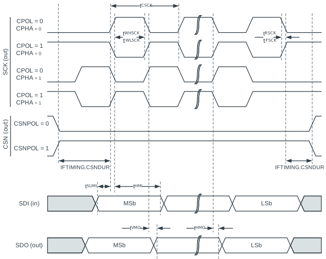
Timing specifications
| Symbol | Description | Min. | Typ. | Max. | Units |
|---|---|---|---|---|---|
| fSPIM | Bit rates for SPIM1 | 8 | Mbps | ||
| tSPIM,START | Time from START task to transmission started | 1 | µs | ||
| tSPIM,CSCK | SCK period | 31.25 | ns | ||
| tSPIM,RSCK,LD | SCK rise time, standard drivea | tRF,25pF | |||
| tSPIM,RSCK,HD | SCK rise time, high drivea | tHRF,25pF | |||
| tSPIM,FSCK,LD | SCK fall time, standard drivea | tRF,25pF | |||
| tSPIM,FSCK,HD | SCK fall time, high drivea | tHRF,25pF | |||
| tSPIM,WHSCK | SCK high timea | (tCSCK/2) - tRSCK - 1.5 ns | |||
| tSPIM,WLSCK | SCK low timea | (tCSCK/2) - tFSCK - 1.5 ns |
1 High bit rates may require GPIOs to be set as High Drive or Extra High Drive, see GPIO chapter for more details.
2 At 25pF load, including GPIO pin capacitance, see GPIO spec.
Timing specifications for GPIO port P1 using Standard drive strength
| Symbol | Description | Min. | Typ. | Max. | Units |
|---|---|---|---|---|---|
| tSPIM,SUMI | SDI to CLK edge setup time | 35 | ns | ||
| tSPIM,HMI | CLK edge to SDI hold time | 0 | ns | ||
| tSPIM,VMO | CLK edge to SDO valid | 4 | ns | ||
| tSPIM,HMO | SDO hold time after CLK edge | -4 | ns |
Timing specifications for GPIO port P1 using High drive strength
| Symbol | Description | Min. | Typ. | Max. | Units |
|---|---|---|---|---|---|
| tSPIM,SUMI | SDI to CLK edge setup time | 32 | ns | ||
| tSPIM,HMI | CLK edge to SDI hold time | 0 | ns | ||
| tSPIM,VMO | CLK edge to SDO valid | 7 | ns | ||
| tSPIM,HMO | SDO hold time after CLK edge | -6 | ns |