Reset
A system reset can be triggered by multiple sources. After a reset the CPU can query the RESETREAS (reset reason register) to find out which source generated the reset.
Power-on reset
The power-on reset generator initializes the system at power-on. The system is held in reset state until the supply has reached the minimum operating voltage and the internal voltage regulators have started.
Pin reset
A pin reset is generated when the physical reset pin (nRESET) on the device is pulled low.
To ensure that reset is issued correctly, the reset pin should be held low for the time specified in Pin reset.
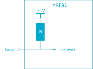
nRESET pin has an always-on internal pull-up resistor connected to nRF9160 internal voltage typically of 2.2 V level, as illustrated in the following figure. The value of the pull-up resistor is given in Pin reset.
Wakeup from System OFF mode reset
The device is reset when it wakes up from System OFF mode.
The Debug access port is not reset following a wake up from System OFF mode if the device is in debug interface mode, see Debug and trace chapter for more information.
Soft reset
A soft reset is generated when the SYSRESETREQ bit of the application interrupt and reset control register (AIRCR register) in the Arm® core is set.
Watchdog reset
A watchdog reset is generated when the watchdog timer (WDT) times out.
See WDT — Watchdog timer chapter for more information.
Brownout reset
The brownout reset generator puts the system in reset state if the supply voltage drops below the brownout reset threshold.
Retained registers
A retained register is a register that will retain its value in System OFF mode, and through a reset depending on reset source. For information on which peripheral registers are retained, see the corresponding peripheral's chapter.
Reset behavior
Reset behavior depends on the reset source.
The reset behavior is summarized in the table below.
| Reset source | Reset target | |||||||
|---|---|---|---|---|---|---|---|---|
| CPU | Modem | Debug1 | SWJ-DP | Not retained RAM2 | Retained RAM2 | WDT | RESETREAS | |
| CPU lockup 3 | x | x | ||||||
| Soft reset | x | x | ||||||
| Wakeup from System OFF mode reset | x | x | x 4 | x | x | |||
| Watchdog reset 5 | x | x | x | x | x | x | ||
| Pin reset | x | x | x | x | x | x | x | |
| Brownout reset | x | x | x | x | x | x | x | x |
| Power-on reset | x | x | x | x | x | x | x | |
| Reset source | Reset target | |||||
|---|---|---|---|---|---|---|
| Regular peripheral registers | GPIO, SPU | NVMC WAITSTATENUM | NVMC IFCREADDELAY | REGULATORS, OSCILLATORS | POWER.GPREGRET | |
| CPU lockup3 | x | x | x | |||
| Soft reset | x | x | x | |||
| Wakeup from System OFF mode reset | x | x | ||||
| Watchdog reset5 | x | x | x | x | ||
| Pin reset | x | x | x | x | ||
| Brownout reset | x | x | x | x | x | x |
| Power-on reset | x | x | x | x | x | x |
Electrical specification
Pin reset
| Symbol | Description | Min. | Typ. | Max. | Units |
|---|---|---|---|---|---|
| tHOLDRESET | Hold time for reset pin when doing a pin reset | 5 | µs | ||
| RPULL-UP | Value of the internal pull-up resistor | 13 | kΩ |