5. Bootrom
Each RP2350 device contains 32 kB of mask ROM: a physically immutable memory resource described in Section 4.1 . The RP2350 bootrom is the binary image etched into this ROM that contains the first instructions executed at reset.
The bootrom concepts section ( Section 5.1 ) covers the following topics, which are necessary background for understanding the bootrom features and their implementation:
- • Partition tables and their associated flash permissions
- • Bootable images , and the block loops that store their metadata
- • Versioning for images and partition tables, and A/B versions to support double-buffered upgrades
- • Hashing and signing to support secure boot with public key fingerprint in OTP (see also Section 10.1.1 in the security chapter)
- • Load maps for bootable images, and packaged binaries that the bootrom loads from flash into RAM according to the image's load map
- • Anti-rollback protection to revoke older, compromised versions of software
- • Three forms of flash boot:
- ◦ Flash image boot , with a single binary image written directly into flash
- ◦ Flash partition boot , with the boot image selected from the partition table
- ◦ Partition-table-in-image boot , where the boot image is not contained in a partition table, but still embeds a partition table data structure to divide the flash address space
- • Boot slots for A/B versions of partition tables
- • Flash update boot , a special one-time boot mode that enables version downgrades following an image download
- • Try before you buy support for phased upgrades with image self-test
- • Address translation for flash images, which provides a consistent runtime address to images regardless of physical storage location
- • Automatic architecture switch when attempting to run a RISC-V binary on Arm, or vice versa
- • Targeting UF2 downloads to different flash partitions based on their permissions and the UF2 family ID
Besides features mentioned as concepts above, the RP2350 bootrom implements:
- • The core 0 initial boot sequence ( Section 5.2 )
- • The core 1 low-power wait and launch protocol ( Section 5.3 )
- • Runtime APIs ( Section 5.4 ) exported through the ROM symbol table, such as flash and OTP programming
- • A subset of runtime APIs available to Non-secure code, with permission for each API entry point individually configured by Secure code
- • A USB MSC class-compliant bootloader with UF2 support for downloading code/data to flash or RAM ( Section 5.5 ), including support for versioning and A/B partitions
- • The USB PICOBOT interface for advanced operations like OTP programming ( Section 5.6 ) and to support picotool or other host side tools
- • Support for white-labelling all USB exposed information/identifiers ( Section 5.7 )
- • A UART bootloader providing a minimal shell to load an SRAM binary from a host microcontroller ( Section 5.8 )
You should read the bootrom concepts section before diving into the features in the list above. RP2350 adds a considerable amount of new functionality compared to the RP2040 bootrom. If you are in a terrible hurry, Section 5.9.5 covers the absolute minimum requirements for a binary to be bootable on RP2350 when secure boot is not enabled.
Bootrom source code
All source files for the RP2350 bootrom are available under the terms of the 3-clause BSD licence:
github.com/raspberrypi/pico-bootrom-rp2350
5.1. Bootrom concepts
Bold type in the following sections introduces a concept . This chapter frequently refers back to these concepts.
5.1.1. Secure and Non-secure
This datasheet uses the (capitalised) terms Secure and Non-secure to refer to the Arm execution states of the same name, defined in the Armv8-M Architecture Reference Manual . The uncapitalised term "secure" has no special meaning.
In some contexts, Secure can also refer to a RISC-V core, usually one running at the Machine privilege level. For example, the low-level flash APIs are exported to Arm Secure code and RISC-V code only, so Secure serves as a shorthand for this type of API.
A secured RP2350 is a device where secure boot is enabled ( Section 5.10.1 ). This is not the same as the Secure state, since the device may run a mixture of Secure and Non-secure code after completing the secure boot process.
5.1.2. Partition tables
A
partition table
divides flash into a maximum of 16 distinct regions, known as
partitions
. Each partition defines attributes such as
flash permissions
for a contiguous range of flash addresses. The
PARTITION_TABLE
data structure describes a partition table, and is an example of a
block
. Use of partition tables is strictly optional.
Dividing flash into multiple partitions enables you to:
- • Store more than one executable image on the device. For example:
- ◦ For A/B boot versions ( Section 5.1.7 )
- ◦ For different architectures (Arm/RISC-V) or Secure/Non-secure
- ◦ For use with a custom bootloader
- • Provision space for data. For example:
- ◦ Embedded file systems
- ◦ Shared Wi-Fi firmware
- ◦ Application resources
- • Provide different security attributes for different regions of flash ( Section 5.1.3 )
- • Target UF2 downloads to different partitions based on family ID ( Section 5.1.18 ), including custom-defined UF2 families specific to your platform
For more information about
PARTITION_TABLE
discovery during flash boot, see
Section 5.1.5.2
.
Partition tables can be versioned to support A/B upgrades. They can also be hashed and signed for security and integrity purposes. We recommend hashing partition tables to ensure that they haven't been corrupted. This is especially important when using boot slots to update your partition table, since a corrupted partition table with a higher version could be chosen over a non-corrupted partition table with a lower version.
5.1.2.1. Partition attributes
Each partition specifies partition attributes for the flash addresses it encompasses, including:
- • Start/end offsets within the logical 32 MB address space of the two flash windows; these offsets are specified in multiples of a flash sector (4 kB)
- ◦ Bootable partitions must reside wholly in the first 16 MB flash window, due to limitations of the address translation hardware
- • Access permissions for the partition: read/write for each of Secure ( S ), Non-secure ( NS ) and bootloader ( BL ) access
- • Information on which UF2 family IDs may be dropped into the partition via the UF2 bootloader
- • An optional 64-bit identifier
- • An optional name (a string for human-readable identification)
- • Whether to ignore the partition during Arm or RISC-V boot
- • Information to group partitions together (see Section 5.1.7 and Section 5.1.18 )
Section 5.9.4 documents the full list of partition attributes, along with the PARTITION_TABLE binary format.
If there is no partition table, the entirety of flash is considered a single region, with no restricted permissions. Without a partition table, there is no support for custom UF2 family IDs, therefore you must use one of the standard IDs specified in Table 455 .
5.1.3. Flash permissions
One of the roles of the partition tables introduced in Section 5.1.2 is to define flash permissions , or simply permissions. The partition table stores one set of permission flags for each partition: all bytes covered by a single partition have the same permissions. The partition table separately defines permissions for unpartitioned space : flash addresses which do not match any of partitions defined in the partition table.
Separate read/write permissions are specified for each of Secure ( S ), Non-secure ( NS ) and bootloader ( BL ) access. Bootloader permissions control where UF2s can be written to, and what can be accessed via picotool when the device is in BOOTSEL mode.
Because flash permissions may be changed dynamically at runtime, part of the partition table is resident in RAM at runtime. You can modify this table to add permissions for other areas of flash at runtime, without changing the partition table stored in flash itself. There is no bootrom API for this, however the in-memory partition table format is documented, and a pointer is available in the ROM table. The SDK provides APIs to wrap this functionality.
5.1.4. Image definitions
An image is a contiguous data blob which may contain code, or data, or a mixture. An image definition is a block of metadata embedded near the start of an image. The metadata stored in the image definition allows the bootrom to recognise valid executable and non-executable images. The IMAGE_DEF data structure represents the image definition in a binary format, and is an example of a block .
For executable images, the IMAGE_DEF could be considered similar to an ELF header, as it can include image attributes such as architecture/chip, entry-point, load addresses, etc.
All IMAGE_DEFS can contain version information and be hashed or signed. Whilst the bootrom only directly boots executable images, it does provide facilities for selecting a valid (possibly signed) data image from one or more partitions on behalf of a user application.
The presence of a valid IMAGE_DEF allows the bootrom to discern a valid application in flash from random data. As a result, you must include a valid IMAGE_DEF in any executable binary that you intend to boot.
For more information about how the bootrom discovers IMAGE_DEFS , see the section on block loops .
For details about the
IMAGE_DEF
format itself, see
Section 5.9.3
.
For a description of the minimum requirements for a bootable image, see Section 5.9.5 .
5.1.5. Blocks and block loops
5.1.5.1. Blocks
IMAGE_DEFS
and
PARTITION_TABLES
are both examples of
blocks
. A block is a recognisable, self-checking data structure containing one or more distinct data
items
. The type of the first item in a block defines the type of that entire block.
Blocks are backwards and forwards compatible; item types will not be changed in the future in ways that could cause existing code to misinterpret data. Consumers of blocks (including the bootrom) must skip items within the block whose types are currently listed as reserved; encountering reserved item types must not cause a block to fail validation.
To be considered valid , a block must have the following properties:
- • it must begin with the 4 byte magic header,
PICOBIN_BLOCK_MARKER_START(0xffffded3) - • the end of each (variably-sized) item must also be the start of another valid item
- • the last item must have type
PICOBIN_BLOCK_ITEM_2BS_LASTand specify the correct full length of the block - • it must end with the 4 byte magic footer,
PICOBIN_BLOCK_MARKER_END(0xab123579)
The magic header and footer values are chosen to be unlikely to appear in executable Arm and RISC-V code. For more information about the block format, see Section 5.9.1 .
Given a region of memory or flash (such as a partition), blocks are found by searching the first 4 kB of that given region (for flash boot) or the entire region (for RAM/OTP image boots) for a valid block which is part of a valid block loop .
Currently
IMAGE_DEFS
and
PARTITION_TABLES
are the only types of block used by the RP2350 bootrom, but the block format reserves encoding space for future expansion.
5.1.5.2. Block loops
A block loop is a cyclic linked list of blocks (a linked loop). Each block has a relative pointer to the next block, and the last block must link to the first. A single block can form a block loop by linking back to itself with a relative pointer of 0. The first block in a loop must have the lowest address of all blocks in the loop.
The purpose of a block loop is threefold:
- • to discover which blocks belong to the same image without a brute-force search
- • to allow metadata to be appended in post-link processing steps
- • to detect parts of the binary being overwritten in a way that breaks the loop
For flash image boot the bootrom searches the first 4 kB of flash; the 4 kB size is a compromise between allowing flexibility for different languages' memory layouts, while avoiding scanning too much flash when trying different flash access modes and QSPI clock frequencies. flash partition boot also limits its search to the first 4 kB of the partition.
The search window may be larger, such as a RAM image boot following a UF2 SRAM download, where the search window is all of SRAM. For the fastest boot time, locate the first block as close to the beginning of the binary as possible.
Block loops support multiple blocks because:
- • Signing an image duplicates the existing
IMAGE_DEFand adds another (bigger)IMAGE_DEFwith additional signature information. - • An image may contain multiple
IMAGE_DEFS, for example, with different signing keys.
- • Placing a block at both the beginning and end of an image can detect some partial overwrites of the image (for example, due to an overly enthusiastic absolute-addressed UF2 download). The SDK does this by default. Hashing or signing the entire image is more robust, since it detects corruption in the middle of the image.
- • A universal binary image might contain code for both Arm and RISC-V, including
IMAGE_DEFSfor both. - •
PARTITION_TABLESandIMAGE_DEFSare both present in the same block loop in the case of an embedded partition table .
If a block loop contains multiple
IMAGE_DEFS
or multiple
PARTITION_TABLES
, the winner is generally the last one seen in linked-list order. The exception is the case of two
IMAGE_DEFS
for different architectures (Arm and RISC-V); an
IMAGE_DEF
for the architecture currently executing the bootrom is always preferred over one for a different architecture.
5.1.6. Block versioning
Any block may contain a
version
. Version information consists of a tuple of either two or three 16-bit values:
(rollback).major.minor
, where the rollback part is optional. An item of type
VERSION
contains the binary data structure which defines the version of a block.
The rollback version may only be specified for
IMAGE_DEFS
and defaults to zero if not present. You cannot specify this version for partition tables. The rollback version can be used on a
secured RP2350
, where it, along with a current rollback version number stored in OTP, can prevent installation of older, vulnerable code once a newer version is installed (
Section 5.1.11
).
The full version number can be used to pick the latest version between two
IMAGE_DEFS
or two
PARTITION_TABLES
(see
Section 5.1.7
). Versions compare in lexicographic order:
- 1. If version x has a different rollback version than version y, then the greater rollback version determines which version is greater overall
- 2. Else if version x has a different major version than version y, then the greater major version determines which version is greater overall
- 3. Else the minor version determines which of x and y is greater
See
Section 5.9.2.1
for full details on the
VERSION
item in a block.
5.1.7. A/B versions
A pair of partitions may be grouped into an A/B pair. By logically grouping A and B partitions, you can keep the current executable image (or data) in one partition, and write a newer version into the other partition. When you finish writing a new version, you can safely switch to it, reverting to the older version if problems arise. This avoids partially written states that could render RP2350 un-bootable.
- • When booting an A/B partition pair, the bootrom typically uses the partition with the higher version. For scenarios where this is not the case, see Section 5.1.16 .
- • When dragging a UF2 onto the BOOTSEL USB drive, the UF2 targets the opposite A/B partition to the one preferred at boot. See Section 5.1.18 for more details.
i NOTE
It is also possible to have A/B versions of the partition table. For more information about this advanced topic, see Section 5.1.15 .
5.1.8. Hashing and signing
Any block may be hashed or signed . A hashed block stores the image hash value (see Section 5.9.2.3 ). At runtime, the bootrom calculates a hash and compares it to the stored hash to determine if the block is valid. Hashes guard against
corruption of an image, but do not provide any security guarantees.
On a secured RP2350, a hash is not sufficient for an image to be considered valid. All images must have a
signature
: a hash encrypted by a private key, plus metadata (also covered by the hash) describing how the hash was generated. This signature is stored as part of an
IMAGE_DEF
block. An image with a signature in its
IMAGE_DEF
block is called a
signed image
.
NOTE
For background on signatures and boot keys, see the introduction to secure boot in the security chapter ( Section 10.1.1 ).
To verify a signed image, the bootrom decrypts the hash stored in the signature using a secp256k1 public key. The bootrom also computes its own hash of the image and compares its measured hash value with the one in the signature.
The public key is also stored in the block via a
SIGNATURE
item (see
Section 5.9.2.4
): this key's (SHA-256) hash must match one of the boot key hashes stored in OTP locations
BOOTKEY0_0
onwards. Up to four public keys can be registered in OTP, with the count defined by
BOOT_FLAGS1.KEY_VALID
and
BOOT_FLAGS1.KEY_INVALID
. A hash of a key is also referred to as a
key fingerprint
.
The data to be hashed is defined by a
HASH_DEF
item (see
Section 5.9.2.2
), which indicates the type of hash. It also indicates how much of the block itself is to be hashed. For a signed block, the hash
must
contain all contents of the block up to the final
SIGNATURE
item.
To be useful your hash or signature must cover actual image data in addition to the metadata stored in the block. The block's
load map
item specifies which data the bootrom hashes during hash or signature verification.
The above discussion mostly applies to
IMAGE_DEFS
. On a secured RP2350 with the
BOOT_FLAGS0.SECURE_PARTITION_TABLE
flag set, the bootrom also enforces signatures on
PARTITION_TABLES
.
5.1.9. Load maps
A load map describes regions of the binary and what to do with them before the bootrom runs the binary.
The load map supports:
- • Copying portions of the binary from flash to RAM (or to the XIP cache)
- • Clearing parts of RAM (either
.bssclear, or erasing uninitialised memory during secure boot) - • Defining what parts of the binary are included in a hash or signature
- • Preventing the flushing of the XIP cache when to keep loaded lines pinned up to the point the binary starts
For full details on the
LOAD_MAP
item type of
IMAGE_DEF
blocks, see
Section 5.9.3.2
.
When booting a signed binary from flash, it is desirable to load the signed data and code into RAM
before
checking the signature and subsequently executing it. Otherwise, an adversary could replace the flash device in between the signature check and execution, subverting the check. For this reason, the load map also serves as a convenient description of what to include in a hash or signature. The load map itself is covered by the hash or signature, and the entire metadata
block
is loaded into RAM before processing, so it is not itself subject to this time-of-check versus time-of-use concern.
5.1.10. Packaged binaries
As described in Section 5.1.9 , signed binaries in flash on a secured RP2350 are commonly loaded from flash into RAM, go through signature verification in RAM, and then execute from the verified version in RAM.
A
packaged binary
is a binary stored in flash that runs entirely from RAM. The binary is likely compiled to run from RAM as a RAM-only binary (unfortunately named
no_flash
in SDK parlance), but subsequently post-processed for flash
residence. The bootrom unpacks the binary into RAM before execution.
As part of the packaging process, tooling like
picotool
adds a
LOAD_MAP
that tells the bootrom which parts of the flash-resident image it must load into RAM, and where to put them. This tooling may also
hash or sign
the binary in the same step. In this case, the bootrom hashes the data it loads as it unpacks the binary, as well as relevant metadata such as the
LOAD_MAP
itself. The bootrom compares the resulting hash to the precomputed hash or signature in the
IMAGE_DEF
to verify the unpacked contents in RAM before running those contents.
Compare this with RP2040, where a flash-resident binary which executes from RAM (a
copy_to_ram
binary in SDK parlance) must begin by executing from flash, then copy itself to RAM before continuing from there. In the RP2040 case, the loader itself (or rather the SDK
crt0
) executes in-place in flash to perform the copy. This makes it impossible to perform any trustworthy level of verification, because the loader itself executes in untrusted memory.
5.1.11. Anti-rollback protection
Anti-rollback on a secured RP2350 prevents booting an older binary which may have known vulnerabilities. It prevents this even if the binary is correctly signed and meets all other requirements for bootability.
Full
IMAGE_DEF
version information is of the form
(rollback).major.minor
, where the rollback part is optional. If a
rollback version
is present, it is accompanied by a list of OTP rows whose ordered values are used to form a
thermometer
of bits indicating the minimum rollback version that may run on the device.
A thermometer code is a base-1 (unary) number where the integer value is one plus the index of the most-significant set bit. For example, the bit strings
00001111
,
00001001
, and
00001000
all encode a value of four, and the all-zeroes bit pattern encodes a value of zero. The bootrom uses this encoding because:
- • it allows OTP rows containing counters to be incremented, and
- • it does not allow them to be decremented
On a secured RP2350, the bootrom compares the rollback version of the
IMAGE_DEF
against the thermometer-coded minimum rollback version stored in OTP. If the
IMAGE_DEF
value is lower, the bootrom refuses to boot the image.
The
IMAGE_DEF
rollback version is covered by the image's signature, thus cannot be modified by an adversary who does not know the signing key. The list of OTP rows which define the chip's minimum rollback version is also stored in the program image, and also covered by the image signature.
The list of OTP rows in the
IMAGE_DEF
must always have at least one bit spare beyond the
IMAGE_DEF
's rollback version (enforced by
picotool
). As a result, older binaries always contain enough information for the bootrom to detect that the chip's minimum rollback version has been incremented past the rollback version in the
IMAGE_DEF
. You can append more rows to the list on newer binaries to accommodate higher rollback versions without ambiguity.
When an executable image with a non-zero rollback version is successfully booted, its rollback version is written to the OTP thermometer. The
BOOT_FLAGS0.ROLLBACK_REQUIRED
flag may be used to
require
an
IMAGE_DEF
have a rollback version on a secured RP2350. This flag is set automatically when updating the rollback version in OTP.
i NOTE
An
IMAGE_DEF
with a rollback version of 0 will not automatically set the
BOOT_FLAGS0.ROLLBACK_REQUIRED
flag, so it is recommended that the minimum rollback version used is 1, unless the
BOOT_FLAGS0.ROLLBACK_REQUIRED
flag is manually set during provisioning.
5.1.12. Flash image boot
RP2350 is designed primarily to run code from a QSPI flash device, either in-package or soldered separately to the circuit board. Code runs either in-place in flash, or in SRAM after being loaded from flash.
Flash boot
is the process of discovering that code and preparing to run it.
Flash image boot
uses a program binary stored directly in flash rather than in a
flash partition
. Flash image boot requires the bootrom to discover a block loop starting within the first 4 kB of flash which contains a valid
IMAGE_DEF
(and no
PARTITION_TABLE
).
Flash image boot has no partition table, so it cannot be used with A/B version checking, which requires separate A/B partitions. The
IMAGE_DEF
will boot if it is valid (which includes requiring a signature on a secured RP2350).
For the non-signed case, the
IMAGE_DEF
can be as small as a 20-bytes; see
Section 5.9.5
.
 TIP
TIP
A more complicated version of this scenario stores multiple
IMAGE_DEFS
in the block loop. In this case, the last
IMAGE_DEF
for the current architecture is booted, if valid. You can use this to implement universal binaries for various supported architectures, or to include multiple signatures for targeting devices with different keys.
5.1.13. Flash partition boot
If a
PARTITION_TABLE
, but no
IMAGE_DEF
, is found in the valid block loop that starts within the first 4 kB of flash, and it is valid (including signature if necessary on a secured RP2350), the bootrom searches that partition table's partitions for an executable image to boot. This process, when successful, is referred to as
flash partition boot
.
The partitions are searched in order, skipping those marked as ignored for the current architecture. The bootrom ignores partitions as an optimisation, or to prevent automatic architecture switching .
If the partition is not part of an A/B pair, the first 4 kB is searched for the start of a valid block loop. If a valid block loop is found, and it contains an executable image with a valid (including signature on a secured RP2350)
IMAGE_DEF
, then that executable image is chosen for boot.
If the partition is the A partition of an A/B pair, the bootrom searches both partitions as described above. If both partitions result in a bootable
IMAGE_DEF
, the
IMAGE_DEF
with the higher version number is chosen. Otherwise, the valid
IMAGE_DEF
is chosen. There are some exceptions to this rule in advanced scenarios; see
Section 5.1.16
and
Section 5.1.17
for details.
5.1.14. Partition-Table-in-Image boot
If both a
PARTITION_TABLE
and an
IMAGE_DEF
block are found in the valid block loop that starts within the first 4 kB of flash, a third type of flash boot takes place. The
IMAGE_DEF
and
PARTITION_TABLE
must only be recognised, not necessarily valid or correctly signed. This stipulation prevents a causality loop.
This is known as partition-table-in-image boot, since the application contains the partition table (instead of vice versa). This partition table is referred to as an embedded partition table .
The
PARTITION_TABLE
is loaded as the current partition table, and the
IMAGE_DEF
is launched directly. The table defined by the
PARTITION_TABLE
is
not
searched for
IMAGE_DEFS
to boot.
The following common cases might use this scenario:
- • You are only using the
PARTITION_TABLEfor flash permissions. You want to load that partition table, then boot as normal. - • The
IMAGE_DEFcontains a small bootloader stored alongside the partition table. In this case, the partition table will once again be loaded, and the associated image entered. The entered image will then likely pick a partition from the partition table, and launch an image from there itself.
5.1.15. Flash boot slots
The previous sections within this chapter discuss block loops starting within the first 4 kB of flash. Such a block loop contained either an
IMAGE_DEF
, a partition table (searched for
IMAGE_DEFS
), or an
IMAGE_DEF
and a
PARTITION_TABLE
(not searched).
All the previously mentioned cases discovered their block loop in slot 0 . Under certain circumstances, the neighbouring slot 1 is also searched.
Slot 0 starts at the beginning of flash, and has a size of
\(
n \times 4
\)
kB sectors. Slot 1 has the same size and follows immediately after slot 0. The value of
\(
n
\)
defaults to 1. Both slots are 4 kB in size, but you can override this value by specifying a value in
FLASH_PARTITION_SLOT_SIZE
and then setting
BOOT_FLAGS0.OVERRIDE_FLASH_PARTITION_SLOT_SIZE
.
Similarly to how a choice can be made between
IMAGE_DEFS
in A/B partitions, a choice can be made between A/B
PARTITION_TABLES
via the two
boot slots
. This allows for versioning partition tables, targeted drag and drop of UF2s (Section 5.1.18) containing partition tables, etc. similar to the process used for images.
Slot 1 is only of use when potentially using partition tables. In the simple case of an
IMAGE_DEF
and no
PARTITION_TABLE
found in a block loop starting in slot 0, that image likely actually overlays the space where slot 1 would be, but in any case, slot 1 is ignored since there is no
PARTITION_TABLE
.
If slot 0 contains a
PARTITION_TABLE
or does not contain an
IMAGE_DEF
(including nothing/garbage in slot 0), slot 1 can be considered. As an optimisation, in the former case, the scanning of slot 1 can be prevented by setting the singleton flag in the
PARTITION_TABLE
.
i NOTE
When
IMAGE_DEFS
are also present in the slots, the
PARTITION_TABLE
's
VERSION
item determines which of slot 0 and slot 1 to use. The
IMAGE_DEF
metadata is ignored for the purpose of version comparison.
5.1.16. Flash update boot and version downgrade
Normally the choice of slot 0 versus slot 1, and partition A versus partition B, is made based on the
version
of the valid
PARTITION_TABLE
or
IMAGE_DEF
in those slots or partitions respectively. The greater of the two versions wins.
It is however perfectly valid to downgrade to a lower-versioned
IMAGE_DEF
when using A/B partitions, provided this does not violate
anti-rollback
rules on a secured RP2350.
Downloading the new image (and its
IMAGE_DEF
) into the non-currently-booting partition and doing a normal reboot will not work in this case, as the newly downloaded image has a lower version.
For this purpose, you can enable a
flash update boot
by passing the
FLASH_UPDATE
boot type constant flag through the watchdog scratch registers and a pointer to the start of the region of flash that has just been updated.
The bootrom automatically performs a flash update boot after programming a flash UF2 written to the USB Mass Storage drive. You can also invoke a flash update boot programmatically via the
reboot()
API (see Section 5.4.8.24).
The flash address range passed through the reboot parameters is treated specially during a flash update boot. A
PARTITION_TABLE
in a slot, or
IMAGE_DEF
in a partition, will be chosen for boot irrespective of version, if the start of the region is the start of the respective slot or partition.
In order for the downgrade to persist, the first sector of the previously booting slot or partition must be erased so that the newly installed
PARTITION_TABLE
or
IMAGE_DEF
will continue to be chosen on subsequent boots. This erase is performed as follows during a
FLASH_UPDATE
boot.
- 1. When a
PARTITION_TABLEis valid (and correctly signed if necessary) and its slot is chosen for boot, the first sector of the other slot is erased. - 2. When a valid (and correctly signed if necessary)
IMAGE_DEFis launched, the first sector of the other image is erased. - 3. On explicit request by the image, after it is launched, the first sector of the other image is erased. This is an alternative to the standard behaviour in the previous bullet, and is selected by a special "Try Before You Buy" flag in the
IMAGE_DEF. For more information about this feature, see Section 5.1.17.
Flash update and version downgrade have no effect when using a single slot, or standalone (non A/B) partitions.
5.1.17. Try before you buy
Try before you buy (abbreviated TBYB ) is an IMAGE_DEF -only feature that allows for a completely safe cycle of version upgrade:
- 1. An executable image is running from say partition B.
- 2. A new image is downloaded into partition A.
- 3. On download completion, a FLASH_UPDATE reboot is performed for the newly updated partition A.
- 4. The bootrom will preferentially try to boot partition A (due to the flash update). Note that a non TBYB image will always be chosen over a TBYB image in A/B partitions during a normal non-
FLASH_UPDATE
boot.
- ◦ If the new image fails validation/signature then the old image in partition B will be used on subsequent (non- FLASH_UPDATE ) boots, recovering from the failed upgrade.
- 5. If the new image is valid (and correctly signed if necessary), it is entered under a watchdog timer, and has 16.7 seconds to mark itself OK via the
explicit_buy()
function.
- ◦ If the image calls back, the first 4 kB sector of the other partition (containing image B) is erased, and the TBYB flag of the current image is cleared, so that A becomes the preferred partition for subsequent boots.
- ◦ If the image does not call back within the allotted time, then the system reboots, and will continue to boot partition B (containing the original image) as partition A is still marked as TBYB image.
The erase of the first sector of the opposite partition in the A/B pair severs its image's block loop , rendering it unbootable. This ensures the tentative image booted under TBYB becomes the preferred boot image going forward, even if the opposite image had a higher version.
The watchdog timeout is fixed at 16.7 seconds (24-bit count on a 1-microsecond timebase). This can be shortened after entering the target image, for example if it only needs a few hundred milliseconds for its self-test routine. It can also be extended by reloading the watchdog counter, at the risk of getting stuck in the tentative image if it fails in a way that repeatedly reloads the watchdog.
5.1.18. UF2 targeting
Section 5.5 describes the USB Mass Storage drive, and the ability to download UF2 files to that drive to store and/or execute code/data on the RP2350.
Since RP2350 supports multiple processor architectures, and partition tables with multiple partitions, some information on the device must be used to determine what to do with a flash-addressed UF2. Depending on the context, the flash addresses in the UF2 may be absolute flash storage addresses (as was always the case on RP2040), or runtime addresses of code and data within a flash partition. UF2 targeting refers to the rules the bootrom applies to interpret flash addresses in a UF2 file.
UF2 supports a 32-bit family ID embedded in the file. This enables the device to recognise firmware that targets it specifically, as opposed to firmware intended for some other device. The RP2350 bootrom recognises some standard UF2 family IDs ( rp2040 , rp2350-arm-s , rp2350-arm-ns , rp2350-riscv , data and absolute ) defined in Table 455 . You may define your own family IDs in the partition table for more refined targeting.
The UF2 family ID is used as follows:
- 1. A UF2 with the absolute family ID is downloaded without regard to partition boundaries. A partition table (if present) or OTP configuration define whether absolute family ID downloads are allowed. The default factory settings do allow for absolute family ID downloads.
- 2. If there is no partition table, then the
data,rp2350-arm-s(if Arm is enabled) andrp2350-riscv(if RISC-V is enabled) family IDs are allowed by default. The UF2 is always downloaded to the start of flash. - 3. If there is a partition table, then non-
absolutefamily IDs target a single partition under the control of the partition table:- a. A UF2 will not be downloaded to a partition that doesn't have BL-write flash permissions
- b. Each partition lists which family IDs it accepts (both RP2350 standard and user defined)
- c. With A/B partitions; the A partition indicates the family IDs supported, and the UF2 goes to the partition that isn't the currently booting one (strictly the one that won't be the one chosen if the device were rebooted now).
- d. Further refinement with A/B is allowed to support secondary A/B partitions containing data/executables used (owned) by the main partitions; see Section 5.1.18.1 for detailed information.
For details of the exact rules used when picking a UF2 target partition, see Section 5.5.3 .
NOTE
UF2 family ids are used for partition targeting when copying UF2s to the USB drive, or when using
picotool load -p
. When using
picotool load
without the
-p
flag images can be written anywhere in flash that has BL-write permissions.
5.1.18.1. Owned partitions
An executable might require data from another partition (such as Wi-Fi firmware). When the main executable is stored in A/B partitions , for safe upgrades, it may be desirable to associate two other partitions C and D with the primary A and B partitions, such that:
- • the data in partition C is used for executable in partition A, and
- • the data in partition D is used for the executable in partition B.
In this scenario A is marked as the owner of C in the partition table, and C is A's owned partition . This affects UF2 image downloads which (due to their UF2 family ID) target partitions C and D.
When a UF2 download targets the C/D partition pair, the bootrom checks the state of the A and B owning partitions to determine which of the owned partitions (C and D) receives the download. By default:
- • If B would be the target partition for a UF2 with an A/B-compatible family ID, then D is the target for a UF2 with the C/D compatible family ID.
- • Conversely, when A is the target partition for A/B downloads, C is the target partition for C/D downloads.
The
FLAGS_UF2_DOWNLOAD_AB_NON_BOOTABLE_OWNER_AFFINITY
flag in the partition table reverses this mapping.
5.1.19. Address translation
RP2040 required images to be stored at the beginning of flash (
0x10000000
). RP2350 supports storing executable images in a partitions at arbitrary locations, to support more robust upgrade cycles via
A/B versions
, among other uses. This presents the issue that the address an executable is linked at, and therefore the binary contents of the image, would have to depend on the address it is stored at. This can be worked around to an extent with position-independent code, at cost to code size and performance.
RP2350 avoids this pitfall with hardware and bootrom support for
address translation
. An image stored at any 4 kB-aligned location in flash can appear at flash address
0x10000000
at runtime. The SDK continues to assume an image base of
0x10000000
by default.
When launching an image from a partition, the bootrom initialises QMI registers
ATRANS0
through
ATRANS3
to map a flash
runtime address
of
0x10000000
(by default) to the flash
storage address
of the start of the partition. It sets the total size of the mapped region to the size of the partition, with a maximum size of 16 MB. Accessing flash addresses beyond the size of the booted partition (but below the
0x11000000
chip select watermark) returns a bus fault.
As an example, if the booted partition was 6 MB big, starting 1 MB into flash, the registers would be set up as follows:
| Name / Memory Start | Flash Start | Size |
|---|---|---|
| ATRANS0 / 0x10000000 | 0x10100000 | 4 MB |
| ATRANS1 / 0x10400000 | 0x10500000 | 2 MB |
| ATRANS2 / 0x10800000 | - | 0 |
| ATRANS3 / 0x10c00000 | - | 0 |
This maps the physical flash range from 0x10100000-0x10700000 to flash addresses 0x10000000-0x10600000, ensuring the partition appears at the start of flash at runtime.
In this case, since ATRANS2 and ATRANS3 aren't needed to map the partition, they could be used by the application to map another part of flash.
Mapping the start of the partition to a runtime address of 0x10000000 is the default behaviour, but you may choose a different address, with some restrictions. The bootrom allows for runtime address values of 0x10000000, 0x10400000, 0x10800000, and 0x10c00000 for the beginning of the mapped regions, with the choice specified in the IMAGE_DEF. You must link your binary to run at the correct, higher base address. This is useful, for example, when an application runs from a high flash address and remains mapped there while launching a second application at address 0x10000000. You might use this setup when a Secure image provides services to a Non-secure client image.
This custom address translation is enabled by a negative ROLLING_WINDOW_DELTA value (see Section 5.9.3.5). The above four runtime addresses translate to a ROLLING_WINDOW_DELTA of 0, -0x400000, -0x800000, or -0xc00000, which are the only supported non-positive values. The delta indicates how many bytes into the partition the runtime address 0x10000000 appears. A negative delta value indicates that address 0x10000000 appears before the start of the partition; the partition starts that many bytes higher than 0x10000000.
Positive values are also useful, for example, when prepending data to an already linked image as a post-processing step. Positive deltas must be multiples of 4 kB. For example, a ROLLING_WINDOW_DELTA of 0x1000 will set up address translation so that the image data starting at offset 0x1000 within the partition is mapped to 0x10000000 at runtime, omitting the first 4 kB of the image from the mapped region. The first 4 kB is inaccessible except through the untranslated XIP window, which defaults to Secure access only.
i NOTE
Because address translation within the 0x10000000 → 0x11000000 and 0x11000000 → 0x12000000 windows is independent, it is only possible to boot from partitions which are entirely contained within the first 16 MB of flash.
This address translation is performed by hardware in the QMI. For more information, see Section 12.14.4.
5.1.20. Automatic architecture switching
If the bootrom encounters a valid and correctly signed IMAGE_DEF for the non-current architecture (RISC-V when booted in Arm mode, or Arm when booted in RISC-V), it performs an automatic architecture switch . The bootrom initiates a reboot into the correct architecture for the binary it discovered, which then boots successfully on the second attempt. Information passed in watchdog scratch registers (such as a RAM image boot type) is retained, so that the second boot makes the same decisions as the first, and arrives at the same preferred image to boot.
This happens only when:
- • The architecture to be switched to is available according to OTP critical flags
- • The architecture switch feature is not disabled by the BOOT_FLAGS0.DISABLE_AUTO_SWITCH_ARCH flag
- • The bootrom found no valid binary for the current architecture before finding one for the other architecture
 TIP
TIPWhen storing executable images for both architectures in flash, it's usually preferable to boot an image for the current architecture. To do this, keep the images in different partitions, marking the partition for Arm as ignored during boot under RISC-V and vice versa. This avoids always picking the image in the first partition and auto-switching to run it under the other architecture.
For hardware support details for architecture switching, see Section 3.9 .
5.2. Processor-controlled boot sequence
The bootrom contains the first instructions the processors execute following a reset. Both processors enter the bootrom at the same time, and in the same location, but the boot sequence runs mostly on core 0.
Core 1 redirects very early in the boot sequence to a low-power state where it waits to be launched, after boot, by user software on core 0. If core 1 is unused, it remains in this low-power state.
Source Code Reference
The sequence described in this section is implemented on Arm by the source files
arm8_bootrom_rt0.S
and
varm_boot_path.c
in the bootrom source code repository. RISC-V cores instead begin from
riscv_bootrom_rt0.S
, but share the boot path implementation with Arm.
5.2.1. Boot outcomes
The bootrom decides the boot outcome based on the following system state:
- • The contents of the attached QSPI memory device on chip select 0, if any
- • The contents of POWMAN registers
BOOT0throughBOOT3 - • The contents of watchdog registers
SCRATCH4throughSCRATCH7 - • The contents of OTP, particularly
CRIT1,BOOT_FLAGS0andBOOT_FLAGS1 - • The QSPI
CSnpin being driven low externally (to select BOOTSEL) - • The QSPI
SD1pin being driven high externally (to select UART boot in BOOTSEL mode)
Based on these, the outcome of the boot sequence may be to:
- • Call code through a
vector
specified in
SCRATCHorBOOTregisters prior to the most recent reboot, for example, into code retained in RAM following a power-up from a low-power state. - • Run an image from external flash.
- ◦ This can happen in one of two ways: either the image runs in-place directly from external flash, or the image is loaded into RAM during the boot sequence.
- ◦ In-package flash on RP2354 is external for boot purposes. It's a separate silicon die, and the RP2350 die doesn't implicitly trust it.
- • Run an image preloaded into SRAM (distinct from the vector case).
- • Load and run an image from OTP into SRAM.
- • Enter the USB bootloader.
- • Enter the UART bootloader.
- • Perform a one-shot operation requested via the
reboot()API, such as a flash update boot . This may be requested
by the user, or by the UART or UF2 bootloaders.
- • Refuse to boot, due to lack of suitable images and the UART and USB bootloaders being disabled via OTP.
This section makes no distinction between the different types of flash boot (flash image boot, flash partition boot and flash partition-table-in-image boot). Likewise, it does not distinguish these types from packaged binaries, which are loaded into RAM at boot time, because these are just flash binaries with a special load map. This section just describes the sequence of decisions the bootrom makes to decide which medium to boot from.
5.2.2. Sequence
This section enumerates the steps of the processor-controlled boot sequence for Arm processors. There are some minor differences on Arm versus RISC-V, which are discussed in Section 5.2.2.2.
A valid image in Table 451 refers to one that contains a valid block loop, with one of those blocks being a valid image definition. On a secured RP2350 this image must be (correctly) signed, and must meet all other security requirements such as minimum rollback version.
Shaded cells in the Action column of Table 451 indicate a boot outcome as described in Section 5.2.1. Other cells are transitory states which continue through the sequence. Both cores start the sequence at Entry.
The main sequential steps in Table 451 are:
- • Entry
- • Core 1 Wait
- • Boot Path Start
- • Await Rescue
- • Generate Boot Random
- • Check POWMAN Vector
- • Check Watchdog Vector
- • Prepare for Image Boot
- • Try RAM Image Boot
- • Check BOOTSEL
- • Try OTP Boot
- • Try Flash Boot
- • Prepare for BOOTSEL
- • Enter USB Boot
- • Enter UART Boot
- • Boot Failure
For a summary of Table 451 in pseudocode form, see Section 5.2.2.1.
Table 451. Processor-controlled boot sequence
| Condition (If...) | Action (Then...) |
|---|---|
| Step: Entry | |
| Always | Check core number in CPUID or MHARTID. |
| Running on core 0 | Clear boot RAM (except for core 1 region and the always region). |
| Go to Boot Path Start. | |
| Running on core 1 | Go to Core 1 Wait. |
| Condition (If...) | Action (Then...) |
|---|---|
| Step: Core 1 Wait | |
| Always | Wait for RCP salt register to be marked valid by core 0. |
| Wait for core 0 to provide an entry point through Secure SIO FIFO, using the protocol described in Section 5.3 . | |
Outcome: Set Secure main
sp
and
VTOR
, then jump into the entry point provided. | |
| Step: Boot Path Start | |
| Always | Check rescue flag,
CHIP_RESET.RESCUE_FLAG |
| Rescue flag set | Go to Await Rescue . |
| Rescue flag clear | Go to Generate Boot Random . |
| Step: Await Rescue | |
| Always | Clear the rescue flag to acknowledge the request. |
| Outcome: Halt in place. The debugger attaches to give the processor further instruction. | |
| Step: Generate Boot Random | |
| Always | Sample TRNG ROSC into the SHA-256 to generate a 256-bit per-boot random number. |
Store 128 bits in boot RAM for retrieval by
get_sys_info()
, and distribute the remainder to the RCP salt registers. | |
| Go to Check POWMAN Vector . | |
| Step: Check POWMAN Vector | |
| Always | Read
BOOT0
through
BOOT3
to determine requested boot type. |
| Boot type parity is valid | Clear
BOOT0
so this is ignored on subsequent boots. |
A
BOOTDIS
flag is set | Go to Check Watchdog Vector . |
Boot type is
VECTOR | Outcome: Set Secure main
sp
, then call into the entry point provided. |
(Return from
VECTOR
) | Go to Check Watchdog Vector . |
| Other or invalid boot type | Go to Check Watchdog Vector . |
| Step: Check Watchdog Vector | |
| Always | Read watchdog
SCRATCH4
through
SCRATCH7
to determine requested boot type. |
| Boot type parity is valid | Clear
SCRATCH4
so this is ignored on subsequent boots. |
Boot type is
BOOTSEL | Make note for later: equivalent to selecting
BOOTSEL
by driving QSPI
CSn
low. |
A
BOOTDIS
flag is set | Go to
Prepare for Image Boot
(so
BOOTSEL
is the only permitted type when the OTP
BOOTDIS.NOW
or POWMAN
BOOTDIS.NOW
flag is set). |
Boot type is
VECTOR | Outcome: Set Secure main
sp
, then call into the entry point provided. |
(Return from
VECTOR
) | Go to Prepare for Image Boot . |
Boot type is
RAM_IMAGE | Make note for later: this requests a scan of a RAM region for a preloaded image. |
Boot type is
FLASH_UPDATE | Make note for later: modifies some flash boot behaviour, as described in Section 5.1.16 . |
| Always | Go to Prepare for Image Boot . |
| Step: Prepare for Image Boot | |
| Condition (If...) | Action (Then...) |
|---|---|
| Always | Clear BOOTDIS flags (OTP BOOTDIS.NOW and POWMAN BOOTDIS.NOW ). |
| Power up SRAM0 and SRAM1 power domains (XIP RAM domain is already powered). | |
| Reset all PADS and IO registers, and remove isolation from QSPI pads. | |
| Release USB reset and clear upper 3 kB of USB RAM (for search workspace). | |
| Go to Try RAM Image Boot . | |
| Step: Try RAM Image Boot | |
| Watchdog type is not RAM_IMAGE | Go to Check BOOTSEL . |
| BOOT_FLAGS0.DISABLE_SRAM_WINDOW_BOOT is set | Go to Check BOOTSEL . |
| Otherwise | Scan indicated RAM address range for a valid image (base in SCRATCH2 , length in SCRATCH3 ). This is used to boot into a RAM image downloaded via UF2, for example. |
| RAM image is valid | Outcome: Enter RAM image in the manner specified by its image definition. |
| No valid image | Go to Prepare for Bootsel (skipping flash and OTP boot). |
| Step: Check BOOTSEL | |
| Always | Check BOOTSEL request: QSPI CSn is low (BOOTSEL button), watchdog type is BOOTSEL , or RUN pin double-tap was detected (enabled by BOOT_FLAGS1.DOUBLE_TAP ). |
| BOOTSEL requested | Go to Prepare for BOOTSEL (skipping flash and OTP boot). |
| Otherwise | Go to Try OTP Boot . |
| Step: Try OTP Boot | |
| Always | Check BOOT_FLAGS0.DISABLE_OTP_BOOT and BOOT_FLAGS0.ENABLE_OTP_BOOT (the disable takes precedence). |
| OTP boot disabled | Go to Try Flash Boot . |
| OTP boot enabled | Load data from OTPBOOT_SRC (in OTP) to OTPBOOT_DST0/OTPBOOT_DST1 (in SRAM), with the length specified by OTPBOOT_LEN . |
| Check validity of the image in-place in SRAM. | |
| Image is valid | Outcome: Enter RAM image in the manner specified by its image definition. |
| No valid image | Go to Try Flash Boot . |
| Step: Try Flash Boot | |
| Flash boot disabled by BOOT_FLAGS0 | Go to Prepare for BOOTSEL . |
| Always | Issue XIP exit sequence to chip select 0. |
| FLASH_DEVINFO has GPIO and size for chip select 1 | Issue XIP exit sequence to chip select 1. |
| Always | Scan flash for a valid image (potentially in a partition) with a range of instructions (EBh, BBh, 0Bh, 03h) and SCK divisors (3 to 24) |
| Condition (If...) | Action (Then...) |
|---|---|
| Valid image found | Outcome: Enter flash image in the manner specified by its image definition. This may including loading some flash contents into RAM. Save the current flash read mode as an XIP setup function at the base of boot RAM, which can be called later to restore the current mode (for example, following a serial programming operation). |
| No valid image | Go to Prepare for BOOTSEL . |
| Step: Prepare for BOOTSEL | |
| Always | Erase SRAM0 through SRAM9, XIP cache and USB RAM to all-zeroes before relinquishing memory and peripherals to Non-secure. |
| Enable XOSC and configure PLL for 48 MHz, according to BOOTSEL_XOSC_CFG and BOOTSEL_PLL_CFG (default is to expect a 12 MHz crystal). | |
| Check QSPI SD1 pin (with default pull-down resistor) for UART/USB boot select. | |
| Scan flash for a partition table (always using an 03h serial read command with an SCK divisor of 6). The USB bootloader may download UF2s to different flash addresses depending on partitions and their contents. | |
| Advance all OTP soft locks to the BL state from OTP, if more restrictive than their S state. | |
| QSPI SD1 pulled low | Go to Enter USB Boot . |
| QSPI SD1 driven high | Go to Enter UART boot . |
| Step: Enter USB Boot | |
| Always | Check BOOT_FLAGS0.DISABLE_BOOTSEL_USB_PICOB00T_IFC and BOOT_FLAGS0.DISABLE_BOOTSEL_USB_MSD_IFC to see which USB interfaces are permitted. |
| Both USB interfaces disabled | Go to Boot Failure . |
| Otherwise | Outcome: Enter USB bootloader. The bootloader reboots if a UF2 image is downloaded, marking a FLASH_UPDATE in the watchdog scratch registers if applicable, and the boot path restarts from Entry . Valid images boot; invalid images usually end up back in the USB bootloader. |
| Step: Enter UART Boot | |
| Always | Check BOOT_FLAGS0.DISABLE_BOOTSEL_UART_BOOT to see if UART boot is permitted. |
| UART boot disabled | Go to Boot Failure . |
| Otherwise | Outcome: Enter UART bootloader. The bootloader reboots once an image has been downloaded, with a RAM_IMAGE boot type, and the boot path restarts from Entry . Valid images boot; invalid images usually end up back in the UART bootloader. |
| Step: Boot Failure | |
| Always | Outcome: Take no further action. No valid boot image was discovered, and the selected BOOTSEL interface was disabled. Attach the debugger to give the processor further instruction. See the boot reason in boot RAM for diagnostics on why the boot failed. |
 TIP
TIPThe bootrom internally refers to BOOTSEL mode as NSBOOT, because the USB and UART bootloaders run in the Non-secure state under Arm. This chapter may also occasionally refer to BOOTSEL as NSBOOT.
5.2.2.1. Boot sequence pseudocodeThe following pseudocode summarises Table 451 .
if (powman_vector_valid && powman_reboot_mode_is_pcp) {
    // This call may return and continue the boot path
    if (correct_arch) powman_vector_pc(); else hang();
}
if (watchdog_vector_valid) {
    // Make note of RAM_IMAGE, FLASH_UPDATE, BOOTSEL reboot types
    check_special_reboot_mode();
    if (watchdog_reboot_mode_is_pcp) {
        // This call may return and continue the boot path
        if (correct_arch) watchdog_vector_pc(); else hang();
    }
}

// RAM image window specified by watchdog_scratch, e.g. after a UF2 RAM
// download: either execute the RAM image or fall back to UART/USB boot.
if (watchdog_reboot_mode_is_ram_image && !ram_boot_disabled_in_otp) {
    // This only returns if there is no valid RAM image to enter.
    // You can't return from the RAM image.
    try_boot_ram_image(ram_image_window);
} else {
    // Otherwise try OTP and flash boot (unless there is a request to skip)
    skip_flash_and_otp_boot =
        bootsel_button_pressed() ||
        watchdog_reboot_mode_is_bootsel ||
        (double_tap_enabled_in_otp() && double_run_reset_detected());

    if (!skip_flash_and_otp_boot) {
        if (otp_boot_enabled_in_otp && !otp_boot_disabled_in_otp) {
            // This only returns if there is no valid OTP image to enter.
            // You can't return from the OTP image.
            try_otp_boot();
        }
        if (!flash_boot_disabled_in_otp) {
            // This only returns if there is no valid flash image to enter.
            // You can't return from the flash image.
            try_flash_boot();
        }
    }
}

// Failed to find an image, so drop down into one of the bootloaders
if (sd1_high_select_uart) {
    // Does not return except via reboot
    if (nsboot_uart_disabled) hang(); else nsboot(uart);
} else {
    // Does not return except via reboot
    if (nsboot_usb_disabled) hang(); else nsboot(usb);
}
5.2.2.2. Differences between Arm and RISC-V
The boot sequence outlined in Table 451 has the following differences on RISC-V:
- • Secure boot is not supported (from any image source).
- • Anti-rollback checking is not supported as it applies only to secure boot.
- • Additional security checks such as the use of the RCP to validate booleans are disabled.
- • The UART and USB bootloaders continue to run in Machine mode, rather than transitioning from the Arm Secure to Non-secure state, meaning there is no hardware-enforced security boundary between these boot phases.
- • The XIP setup function written to boot RAM on a successful flash boot contains RISC-V rather than Arm instructions.
5.2.3. POWMAN boot vector
POWMAN contains scratch registers similar to the watchdog scratch registers, which persist over power-down of the switched core power domain, in addition to most system resets. These registers allow users to install their own boot handler, and divert control away from the main boot sequence on non-POR/BOR resets. It recognises the following values written to BOOT0 through BOOT3 :
- •
BOOT0
: magic number
0xb007c0d3 - •
BOOT1
: Entry point Xored with magic
-0xb007c0d3(0x4ff83f2d) - • BOOT2 : Stack pointer
- • BOOT3 : Entry point
Use this to vector into code preloaded in RAM which was retained during a low-power state.
If either of the magic numbers mismatch, POWMAN vector boot does not take place. If the numbers match, the bootrom zeroes BOOT0 before entering the vector, so that the behaviour does not persist over subsequent reboots.
The POWMAN boot vector is permitted to return. The boot sequence continues as normal after a return from POWMAN vector boot, as though the vector boot had not taken place. There is no requirement for the vector to preserve the global pointer ( gp ) register on RISC-V. Use this to perform any additional setup required for the boot path, such as issuing a power-up command to an external QSPI device that may have been powered down (for example, through a B9h power-down command).
The entry point ( pc ) must have the LSB set on Arm (the Thumb bit) and clear on RISC-V. If this condition is not met, the bootrom assumes you have passed a RISC-V function pointer to an Arm processor (or vice versa) and hangs the core rather than continuing, since executing code for the wrong architecture has spectacularly undefined consequences.
The linker should automatically set the Thumb bit appropriately for a function pointer relocation, but this is something to be aware of if you pass hardcoded values such as the base of SRAM: this is correctly passed as
0x20000001
on Arm (Thumb bit set) and
0x20000000
on RISC-V (no Thumb bit, halfword-aligned).
5.2.4. Watchdog boot vector
Watchdog boot allows users to install their own boot handler, and divert control away from the main boot sequence on non-POR/BOR resets. It recognises the following values written to the watchdog's upper scratch registers:
- •
SCRATCH4
: magic number
0xb007c0d3 - •
SCRATCH5
: entry point Xored with magic
-0xb007c0d3(0x4ff83f2d) - • SCRATCH6 : stack pointer
- • SCRATCH7 : entry point
If either of the magic numbers mismatch, watchdog boot does not take place. If the numbers match, the Bootrom
zeroes SCRATCH4 before transferring control, so that the behaviour does not persist over subsequent reboots.
Watchdog boot can also be used to select the bootrom's special one-shot boot modes, described in
Section 5.2.4.1
. The term
one-shot
refers to the fact these only affect the next boot (and not subsequent ones) due to the bootrom clearing
SCRATCH4
each boot. These boot types are encoded by setting a special entry point (
pc
) value of
0xb007c0d3
, which is otherwise not a valid entry address, and then setting the boot type in the stack pointer (
sp
) value.
Section 5.2.4.1
lists the supported values.
The watchdog boot vector is permitted to return. The boot path continues as normal when it returns: use this to perform any additional setup required for the boot path, such as issuing additional commands to an external QSPI device. On RISC-V the vector is permitted to use its own global pointer ( gp ) value, as the bootrom only uses gp during USB boot, which installs its own value.
With the exception of the magic boot type entry point (
0xb007c0d3
), the vector entry point
pc
must have the LSB set on Arm (the Thumb bit) and clear on RISC-V. If this condition is not met, the bootrom assumes you have passed a RISC-V function pointer to an Arm processor (or vice versa) and hangs the core rather than continuing.
5.2.4.1. Special watchdog boot types
The magic entry point
0xb007c0d3
indicates a special one-shot boot type, identified by the stack pointer value:
BOOTSEL
Selected by sp = 2. Boot into BOOTSEL mode. This will be either UART or USB boot depending on whether QSPI SD1 is driven high (default pull-down selects USB boot). See Section 5.2.8 for more details.
RAM_IMAGE
Selected by sp = 3. Boot into an image stored in SRAM or XIP SRAM. BOOTSEL mode uses this to request execution of an image it loaded into RAM before rebooting. See Section 5.2.5 for more details.
FLASH_UPDATE
Selected by sp = 4. BOOTSEL selects this mode when rebooting following a flash download. Changes some flash boot behaviour, such as allowing older versions to boot in preference to newer ones. See Section 5.1.16 for more details.
Parameters to the one-shot boot type are passed in:
These directly correspond to the p0 and p1 boot parameters passed into the reboot() API. For example, on a RAM_IMAGE boot, this specifies the base and size of the RAM region to be searched for a valid IMAGE_DEF . See the API listing in Section 5.4.8.24 for more details. When not performing one of the listed boot types, SCRATCH2 and SCRATCH3 remain free for arbitrary user values, and the bootrom doesn't modify or interpret their contents.
5.2.5. RAM image boot
The bootrom is directed (through values in the watchdog registers) to boot into an image in SRAM or XIP SRAM. The two parameters indicate the start and size of the region to search for a block loop containing a valid (and correctly signed if necessary) IMAGE_DEF . These are passed as parameter 0/1, in watchdog scratch 2/3.
If the image to be booted is contained in XIP SRAM, the XIP SRAM must be pinned in place by the bootrom prior to launch. For this reason, if you are using XIP SRAM for your binaries, you must add a special entry to the LOAD_MAP item (see Section 5.9.3.2 ).
5.2.6. OTP boot
If OTP boot is enabled, then code from OTP is executed in preference to code from flash. Note that the OTP code is free to "chain" into an executable stored in flash.
Code from OTP is copied into SRAM at the specified location, then execution proceeds similarly to RAM Image Boot. The SRAM with the data copied from OTP is searched for a valid (and correctly signed if necessary)
IMAGE_DEF
. If found, it is booted; otherwise OTP boot falls through to Flash Boot (if enabled).
OTP boot could, for example, be used to execute some hidden decryption code to decode a flash image on startup. The OTP boot code can hide itself (in OTP) even from Secure code, once it is done.
5.2.7. Flash boot
The bootrom scans flash up to 16 times until it finds a valid
IMAGE_DEF
or
PARTITION_TABLE
. At this point, the flash settings are considered valid, and the flash boot proceeds if a valid bootable
IMAGE_DEF
is found with these settings. It uses the following combinations of flash read instruction and SCK divisor for the 16 attempts:
Table 452. QSPI read modes supported by the bootrom, in the order it attempts them.
| Mode | Clock Divisor |
|---|---|
| EBh quad | 3 |
| BBh dual | 3 |
| 0Bh serial | 3 |
| 03h serial | 3 |
| EBh quad | 6 |
| BBh dual | 6 |
| 0Bh serial | 6 |
| 03h serial | 6 |
| EBh quad | 12 |
| BBh dual | 12 |
| 0Bh serial | 12 |
| 03h serial | 12 |
| EBh quad | 24 |
| BBh dual | 24 |
| 0Bh serial | 24 |
| 03h serial | 24 |
QSPI does not provide a reliable method to detect whether a device is attached. However, this is not much of an issue for boot purposes: either there is a device with valid and bootable contents, or there are no such contents (either due to lack of a connected device, invalid device contents, or failure to communicate in the current QSPI mode).
When there is no device (or no recognisable contents), the bootrom tries all 16 modes in Table 452 before finally giving up. The size of the initial search region is limited to 4 kB to minimise the time spent scanning flash before falling through to USB or UART boot. This same 4 kB limit also applies to search within a flash partition , which allows the bootrom to reliably sever the contained image's block loop with a single 4 kB sector erase at the start of a partition, such as on a version downgrade .
There are three main ways that the bootrom locates flash images:
Flash image boot
A flash image can be written directly to flash storage address
0x0
, and the bootrom will find it from there. This is the most similar to flash boot on RP2040 (the main differences being the removal of a
boot2
in the first 256 bytes of the image, and the new requirement for a valid
image definition
anywhere within the first 4 kB of the image).
Flash partition boot
A flash image can be written into a partition of a
partition table
. The partition table is described by a
PARTITION_TABLE
block stored at the start of flash. The bootrom finds the partition table and scans its partitions to look for bootable images.
Partition-table-in-image boot
A flash image containing an
IMAGE_DEF
and
PARTITION_TABLE
block in a single
block loop
is written to the start of flash. The bootrom loads the embedded partition table, and enters the image in the same way as the
flash image boot
case.
Revisit the linked bootrom concepts sections to get the fullest understanding of each of these three forms of flash boot. For the purposes of this section, all that matters is whether the bootrom can discover a valid, bootable image or not. In all three cases, the image must have a valid
IMAGE_DEF
, and meet all relevant security requirements such as being correctly
signed
, and having a
rollback version
greater than or equal to the one stored in OTP.
The bootrom enters the flash image in whatever QSPI mode it discovered to work during flash programming. Any further setup (such as prefixless continuous read modes) is performed by the flash image itself. This setup code, referred to as an XIP setup function , is usually copied into RAM before execution to avoid running from flash whilst the XIP interface is being reconfigured.
 TIP
TIP
The
PICO_EMBED_XIP_SETUP=1
flag in the SDK enables inclusion and execution of an XIP setup function on RP2350 builds. In this case the function executes on the core 0 stack during early startup, so no additional static memory need be allocated. This is not the case for subsequent calls, because the stack is often not executable post-startup.
You should save your XIP setup function in the first 256 bytes of boot RAM to make it easily locatable when the XIP mode is re-initialised following a serial flash programming operation which had to drop out of XIP mode. The bootrom writes a default XIP setup function to this address before entering the flash image, which restores the mode the bootrom discovered during flash programming.
 NOTE
NOTE
You cannot execute an XIP setup function directly from boot RAM, because boot RAM is never executable. You must copy it into SRAM before execution.
XIP setup functions should be fully position-independent, and no more than 256 bytes in size. If you are unable to meet these requirements, you should install a stub function which calls your XIP setup function elsewhere in RAM.
5.2.8. BOOTSEL (USB/UART) boot
The bootrom samples the state of QSPI
CSn
shortly after reset. Based on the result, the bootrom decides whether to enter BOOTSEL mode, which refers collectively to the USB and UART bootloaders.
The bootrom initialises the chip select to the following state:
- • Output disabled
- • Pulled high (note
CSnis an active-low signal, so this deselects the external QSPI device if there is one)
If the chip select remains high, the bootrom continues with its normal, non-BOOTSEL sequence. By default on a blank device, this means driving the chip select low and attempting to boot from an external flash or PSRAM device.
If chip select is driven low externally, the bootrom enters BOOTSEL mode. You must drive the chip select low with a
sufficiently low impedance to overcome the internal pull-up. A 4.7 kΩ resistance to ground is a good intermediate value which reliably creates a low input logic level, but will not affect the output levels when RP2350 drives the chip select.
The QSPI SD1 line, which RP2350 initially pulls low, selects which bootloader to enter:
USB boot is a low-friction method for programming an RP2350 from a sophisticated host like a Linux PC. It also directly exposes more advanced options like OTP programming. See Section 5.5 for the drag-and-drop mass storage interface, or Section 5.6 for the PICOBOT vendor interface.
UART boot is a minimal interface for bootstrapping a flashless RP2350 from another microcontroller. UART boot uses QSPI SD2 for UART TX, and QSPI SD3 for UART RX, at a fixed baud rate of 1 Mbaud. For more details about UART boot, see Section 5.8 .
5.2.8.1. BOOTSEL clock requirements
BOOTSEL mode requires either a crystal attached across the XIN and XOUT pins, or a clock signal from an external oscillator driven into the XIN pin. See Table 1439 for the electrical specifications of these two XOSC pins.
The bootrom assumes a default XOSC frequency of 12 MHz. It configures the USB PLL to derive a fixed 48 MHz frequency from the XOSC reference. For USB, this must be a precise frequency. If you use a non-12 MHz crystal, and intend to use USB boot, program BOOTSEL_PLL_CFG and BOOTSEL_XOSC_CFG in OTP, and then set BOOT_FLAGS0.ENABLE_BOOTSEL_NON_DEFAULT_PLL_XOSC_CFG . For details about calculating the correct PLL parameters for your crystal, see Section 8.6.3 .
UART boot uses the same PLL configuration as USB boot. However, the permissible range of crystal frequencies under the default PLL configuration is wider. See Section 5.8.1 .
5.2.9. Boot configuration (OTP)
User configuration stored in OTP can be found in Section 13.10 , starting at CRIT1 .
The main controls for the bootrom are stored in BOOT_FLAGS0 and BOOT_FLAGS1 . These are both in page 1 of OTP, which has the following default permissions on a blank device:
Boot key hashes are stored in page 2 of OTP, starting from BOOTKEY0_0 . There is space for up to four boot key hashes in this page. See Section 5.10.1 for an example of how keys can be installed.
5.3. Launching code on Processor Core 1
As described in Section 5.2 , after reset, processor core 1 sleeps at start-up, and remains asleep until woken by core 0 via the SIO FIFOs.
If you are using the SDK then you can use the
multicore_launch_core1()
function to launch code on processor core 1. However this section describes the procedure to launch code on processor core 1 yourself.
The procedure to start running on processor core 1 involves both cores moving in lockstep through a state machine coordinated by passing messages over the inter-processor FIFOs. This state machine is designed to be robust enough to cope with a recently reset processor core 1 which may be anywhere in its boot code, up to and including going to sleep. As result, the procedure may be performed at any point after processor core 1 has been reset (either by system
reset, or explicitly resetting just processor core 1).
The following C code describes the procedure:
// values to be sent in order over the FIFO from core 0 to core 1
//
// vector_table is value for VTOR register
// sp is initial stack pointer (SP)
// entry is the initial program counter (PC) (don't forget to set the thumb bit!)
const uint32_t cmd_sequence[] =
    {0, 0, 1, (uintptr_t) vector_table, (uintptr_t) sp, (uintptr_t) entry};

uint seq = 0;
do {
    uint cmd = cmd_sequence[seq];
    // always drain the READ FIFO (from core 1) before sending a 0
    if (!cmd) {
        // discard data from read FIFO until empty
        multicore_fifo_drain();
        // execute a SEV as core 1 may be waiting for FIFO space
        __sev();
    }
    // write 32 bit value to write FIFO
    multicore_fifo_push_blocking(cmd);
    // read 32 bit value from read FIFO once available
    uint32_t response = multicore_fifo_pop_blocking();
    // move to next state on correct response (echo-d value) otherwise start over
    seq = cmd == response ? seq + 1 : 0;
} while (seq < count_of(cmd_sequence));
5.4. Bootrom APIs
Whilst some ROM space is dedicated to the implementation of the boot sequence and USB/UART boot interfaces, the bootrom also contains public functions that provide useful RP2350 functionality that may be useful for any code or runtime running on the device.
A categorised list is available in Section 5.4.6 .
The full alphabetical list is available in Section 5.4.7 .
5.4.1. Locating the API functions
The API functions are normally made available to the user by wrappers in the SDK. However, a lower level method is provided to locate them (since their locations may change with each bootrom release) for other runtimes, or those who wish to locate them directly.
Table 453 shows the fixed memory layout of certain words in the bootrom used to locate these functions when using the Arm architecture. Table 454 shows the additional entries for use when using the RISC-V architecture.
Table 453. Bootrom contents at fixed (well known) addresses for Arm code
| Address | Contents | Description |
|---|---|---|
| 0x00000000 | 32-bit pointer | Initial boot stack pointer |
| 0x00000004 | 32-bit pointer | Pointer to boot reset handler function |
| 0x00000008 | 32-bit pointer | Pointer to boot NMI handler function |
| 0x0000000c | 32-bit pointer | Pointer to boot Hard fault handler function |
| Address | Contents | Description |
|---|---|---|
| 0x00000010 | 'M', 'u', 0x02 | Magic |
| 0x00000013 | byte | Bootrom version |
| 0x00000014 | 16-bit pointer | Pointer to ROM entry table (
BOOTROM_ROMTABLE_START
) |
| 0x00000016 | 16-bit pointer | Pointer to a helper function (
rom_table_lookup_val()
) |
| 0x00000018 | 16-bit pointer | Pointer to a helper function (
rom_table_lookup_entry()
) |
Table 454. Bootrom contents at fixed (well known) addresses for RISC-V code
| Address | Contents | Description |
|---|---|---|
| 0x00007df6 | 16-bit pointer | Pointer to ROM entry table (
BOOTROM_ROMTABLE_START
) |
| 0x00007df8 | 16-bit pointer | Pointer to a helper function (
rom_table_lookup_val()
) |
| 0x00007dfa | 16-bit pointer | Pointer to a helper function (
rom_table_lookup_entry()
) |
| 0x00007dfc | 32-bit instruction | RISC-V Entry Point |
Assuming the three bytes starting at address
0x00000010
are ('M', 'u',
0x02
), the other fixed location fields can be assumed to be valid and used to lookup bootrom functionality.
The version byte at offset
0x00000013
is informational, and should not be used to infer the exact location of any functions. It has the value 2 for A2 silicon.
The following code from the SDK shows how the SDK looks up a bootrom function:
static __force_inline void *rom_func_lookup_inline(uint32_t code) {
#ifdef __riscv
    // on RISC-V the code (a jmp) is actually embedded in the table
    rom_table_lookup_fn rom_table_lookup =
        (rom_table_lookup_fn) (uintptr_t)*(uint16_t*)(BOOTROM_TABLE_LOOKUP_ENTRY_OFFSET
            + rom_offset_adjust);
    return rom_table_lookup(code, RT_FLAG_FUNC_RISCV);
#else
    // on Arm the function pointer is stored in the table, so we dereference it
    // via lookup() rather than lookup_entry()
    rom_table_lookup_fn rom_table_lookup =
        (rom_table_lookup_fn) (uintptr_t)*(uint16_t*)(BOOTROM_TABLE_LOOKUP_OFFSET);
    if (pico_processor_state_is_nonsecure()) {
        return rom_table_lookup(code, RT_FLAG_FUNC_ARM_NONSEC);
    } else {
        return rom_table_lookup(code, RT_FLAG_FUNC_ARM_SEC);
    }
#endif
}
As well as API functions, there are a few data values that can be looked up. The following code demonstrates:
void *rom_data_lookup(uint32_t code) {
    rom_table_lookup_fn rom_table_lookup =
        (rom_table_lookup_fn) (uintptr_t)*(uint16_t*)(BOOTROM_TABLE_LOOKUP_OFFSET);
    return rom_table_lookup(code, RT_FLAG_DATA);
}
The
code
parameter correspond to the
CODE
values in the tables below, and is calculated as follows:
uint32_t rom_table_code(char c1, char c2) {
    return (c2 << 8) | c1;
}
These codes are also available in
bootrom.h
in the SDK as
#defines
.
5.4.2. API function availability
Some functions are not available under all architectures or security levels. The API listing in Section 5.4.6 uses the following terms to list the availability of each individual API entry point:
Arm-S
The function is available to Secure Arm code. The majority of functions are available for Arm-S unless they deal specifically with RISC-V or Non-secure functionality.
RISC-V
The function is available to RISC-V code. Most of the functions that are available under Arm-S are also exposed under RISC-V unless they deal specifically with Arm security states.
Arm-NS
The function is available to Non-secure Arm code. The function in this case performs additional permission and argument checks to prevent Secure data from leaking or being corrupted.
Each individual
Arm-NS
API function must be explicitly enabled by Secure code before use, via
set_ns_api_permission()
. A disabled Non-secure API returns
BOOTROM_ERROR_NOT_PERMITTED
if disabled by Secure code. All Non-secure APIs are disabled initially. There is no permission control on Non-secure code calling Secure-only
Arm-S
functions, but such a call will crash when it attempts to access Secure-only hardware.
The Arm-NS functions may escalate through a Secure Gateway (SG) instruction to allow Non-secure code to perform limited operations on nominally Secure-only hardware, such as QSPI direct-mode interface used for flash programming.
The RISC-V functions do not have separate entry points based on privilege level. Both M-mode and U-mode software can call bootrom APIs, assuming they have execute permissions on ROM addresses in the PMP. However, U-mode calls will crash if they attempt to access M-mode-only hardware.
5.4.3. API function return codes
Some functions do not support returning any error, and are marked
void
. The remainder return either 0 (
BOOTROM_OK
) or a positive value (if data needs to be returned) for success. These bootrom error codes are identical to the error codes used by the SDK, so they can be used interchangeably. This explains the gaps in the numbering for SDK error codes that aren't used by the bootrom.
| Name | Value | Description |
|---|---|---|
| value | >= 0 | The function succeeded and returned the value |
BOOTROM_OK | 0 | The function executed successfully |
BOOTROM_ERROR_NOT_PERMITTED | -4 | The operation was disallowed by a security constraint |
BOOTROM_ERROR_INVALID_ARG | -5 | One or more parameters passed to the function is outside the range of supported values;BOOTROM_ERROR_INVALID_ADDRESS
andBOOTROM_ERROR_BAD_ALIGNMENT
are more specific errors. |
| Name | Value | Description |
|---|---|---|
BOOTROM_ERROR_INVALID_ADDRESS | -10 | An address argument was out-of-bounds or was determined to be an address that the caller may not access. |
BOOTROM_ERROR_BAD_ALIGNMENT | -11 | An address passed to the function was not correctly aligned. |
BOOTROM_ERROR_INVALID_STATE | -12 | Something happened or failed to happen in the past, and consequently the request cannot currently be serviced. |
BOOTROM_ERROR_BUFFER_TOO_SMALL | -13 | A user-allocated buffer was too small to hold the result or working state of the function. |
BOOTROM_ERROR_PRECONDITION_NOT_MET | -14 | The call failed because another bootrom function must be called first. |
BOOTROM_ERROR_MODIFIED_DATA | -15 | Cached data was determined to be inconsistent with the full version of the data it was copied from. |
BOOTROM_ERROR_INVALID_DATA | -16 | The contents of a data structure are invalid |
BOOTROM_ERROR_NOT_FOUND | -17 | An attempt was made to access something that does not exist; or, a search failed. |
BOOTROM_ERROR_UNSUPPORTED_MODIFICATION | -18 | Modification is impossible based on current state. This might occur, for example, when attempting to clear an OTP bit. |
BOOTROM_ERROR_LOCK_REQUIRED | -19 | A required lock is not owned. See Section 5.4.4 . |
5.4.4. API functions and exclusive access
Various bootrom functions require access to parts of the system which:
- • cannot be safely accessed by both cores at once, or
- • limit the functionality of other hardware when in use
For example:
- • Programming OTP: it is not possible to read from the memory mapped OTP data regions at the same time as accessing its serial programming interface.
- • Use of the SHA-256 block: only one SHA-256 sum can be in progress at a time.
- • Using the QSPI direct-mode interface to program the flash causes XIP access to return a bus fault.
It is beyond the purview of the bootrom to implement a locking strategy, as the style and scope of the locking required is entirely up to how the application itself uses these resources.
Nevertheless, it is important that, say, a Non-secure call to a flash programming API can't cause a hard fault in other Secure code running from flash. There must be some way for user software to coordinate with bootrom APIs on such changes of state. The bootrom implements the mechanism but not the policy for mutual exclusion over bootrom API calls.
The solution the bootrom provides is to use the boot locks (boot RAM registers
BOOTLOCK0
through
BOOTLOCK7
) to inform the bootrom which resources are currently owned by the caller and therefore safe for it to use.
To enable lock checking in bootrom APIs, set boot lock 7 (
LOCK_ENABLE
) to the claimed state. When enabled, bootrom functions which use certain hardware resources (listed below) will check the status of the boot lock assigned to that resource, and return
BOOTROM_ERROR_LOCK_REQUIRED
if that lock is not in the claimed state.
Before calling a bootrom function with locking enabled, you must claim the relevant locks. It may take multiple attempts
to claim if the API is concurrently accessed from other contexts. Follow the same steps as the SIO spinlocks ( Section 3.1.4 ) to claim a lock.
The following boot locks are assigned:
- •
0x0 : LOCK_SHA_256- if owned, then a bootrom API is allowed to use the SHA-256 block - •
0x1 : LOCK_FLASH_OP- if owned, then a bootrom API is allowed to enter direct mode on the QSPI memory interface ( Section 12.14.5 ) in order to perform low-level flash operations - •
0x2 : LOCK_OTP- if owned, then a bootrom API is allowed to access OTP via the serial interface - •
0x7 : LOCK_ENABLE- if owned, then bootrom API resource ownership checking is enabled. This is off by default, since the bootrom APIs aim to be usable by default without additional setup.
5.4.5. SDK access to the API
Bootrom functions are exposed in the SDK via the
pico_bootrom
library (see
pico_bootrom
).
Each bootrom function has a
rom_
wrapper function that looks up the bootrom function address and calls it.
The SDK provides a simple implementation of exclusive access via
bootrom_acquire_lock_blocking(n)
and
bootrom_release_lock(n)
. When enabled, as it is by default (
PICO_BOOTROM_LOCKING_ENABLED=1
is defined) the SDK enables bootrom locking via
LOCK_ENABLE
, and these two functions use the other
SHA_256/FLASH_OP/OTP
boot locks to take ownership of/release ownership of the corresponding bootrom resource.
The
rom_
wrapper functions the SDK call
bootrom_acquire_lock_blocking
and
bootrom_release_lock
functions around bootrom calls that have locking requirements.
5.4.6. Categorised list of API functions and ROM data
The terms in parentheses after each function name ( Arm-S , Arm-NS , RISC-V ) indicate the architecture and security state combinations where that API is available:
- • Arm-S : Arm processors running in the Secure state
- • Arm-NS : Arm processors running in the Non-secure state
- • RISC-V : RISC-V processors
See Section 5.4.2 for the full definitions of these terms.
List entries ending with parentheses, such as
flash_op()
, are callable functions. List entries without parentheses, such as
git_revision
, are pointers to ROM data locations.
5.4.6.1. Low-level Flash access
These low-level (Secure-only) flash access functions are similar to the ones on RP2040:
- •
connect_internal_flash()( Arm-S , RISC-V ) - •
flash_enter_cmd_xip()( Arm-S , RISC-V ) - •
flash_exit_xip()( Arm-S , RISC-V ) - •
flash_flush_cache()( Arm-S , RISC-V ) - •
flash_range_erase()( Arm-S , RISC-V ) - •
flash_range_program()( Arm-S , RISC-V )
These are new with RP2350:
- •
flash_reset_address_trans()(Arm-S, RISC-V) - •
flash_select_xip_read_mode()(Arm-S, RISC-V)
5.4.6.2. High-level flash access
The higher level access functions, provide functionality that is safe to expose (with permissions) to Non-secure code as well.
- •
flash_op()(Arm-S, Arm-NS, RISC-V) - •
flash_runtime_to_storage_addr()(Arm-S, Arm-NS, RISC-V)
5.4.6.3. System information
- •
flash_devinfo16_ptr(Arm-S, RISC-V) - •
get_partition_table_info()(Arm-S, Arm-NS, RISC-V) - •
get_sys_info()(Arm-S, Arm-NS, RISC-V) - •
git_revision(Arm-S, Arm-NS, RISC-V)
5.4.6.4. Partition tables
- •
get_b_partition()(Arm-S, RISC-V) - •
get_uf2_target_partition()(Arm-S, RISC-V) - •
pick_ab_partition()(Arm-S, RISC-V) - •
partition_table_ptr(Arm-S, RISC-V) - •
load_partition_table()(Arm-S, RISC-V)
5.4.6.5. Bootrom memory and state
- •
set_bootrom_stack()(RISC-V) - •
xip_setup_func_ptr(Arm-S, RISC-V) - •
bootrom_state_reset()(Arm-S, RISC-V)
5.4.6.6. Executable image management
- •
chain_image()(Arm-S, RISC-V) - •
(explicit_buy)(Arm-S, RISC-V)
5.4.6.7. Security
These Secure-only functions control access for Non-secure code:
- •
set_ns_api_permission()(Arm-S) - •
set_rom_callback()(Arm-S, RISC-V) - •
validate_ns_buffer()(Arm-S, RISC-V)
5.4.6.8. Miscellaneous
These functions are provided to all platforms and security levels, but perform additional checks when called from Non-secure Arm code:
- •
reboot()(Arm-S, Arm-NS, RISC-V) - •
otp_access()(Arm-S, Arm-NS, RISC-V)
5.4.6.9. Non-secure only
- •
secure_call()(Arm-NS)
5.4.6.10. Bit manipulation
Unlike RP2040, the bootrom doesn't contain bit manipulation functions. Processors on RP2350 implement hardware instructions for these operations which are far faster than the software implementations in the RP2040 bootrom.
5.4.6.11. Malloc and Memset
Unlike RP2040, the bootrom doesn't provide memory copy or clearing functions, as your language runtime is expected to already provide well-performing implementations of these on Cortex-M33 or Hazard3.
The bootrom does contain private implementations of standard C
memcpy()
and
memset()
, for both Arm and RISC-V, but these are optimised for size rather than performance. They are not exported in the ROM table.
5.4.6.12. Floating point
Unlike RP2040 the bootrom doesn't contain functions for floating point arithmetic. On Arm there is standard processor support for single-precision arithmetic via the Cortex-M FPU, and RP2350 provides an Arm coprocessor which dramatically accelerates double-precision arithmetic (the DCP, Section 3.6.2 ). The SDK defaults to the most performant hardware or software implementation available.
5.4.7. Alphabetical list of API functions and ROM data
- •
bootrom_state_reset()(Arm-S, RISC-V) - •
chain_image()(Arm-S, RISC-V) - •
connect_internal_flash()(Arm-S, RISC-V) - •
flash_devinfo16_ptr(Arm-S, RISC-V) - •
flash_enter_cmd_xip()(Arm-S, RISC-V) - •
flash_exit_xip()(Arm-S, RISC-V) - •
flash_flush_cache()(Arm-S, RISC-V) - •
flash_op()(Arm-S, Arm-NS, RISC-V) - •
flash_range_erase()(Arm-S, RISC-V) - •
flash_range_program()(Arm-S, RISC-V) - •
flash_reset_address_trans()(Arm-S, RISC-V) - •
flash_runtime_to_storage_addr()(Arm-S, Arm-NS, RISC-V)
- • flash_select_xip_read_mode() (Arm-S, RISC-V)
- • get_b_partition() (Arm-S, RISC-V)
- • get_partition_table_info() (Arm-S, Arm-NS, RISC-V)
- • get_sys_info() (Arm-S, Arm-NS, RISC-V)
- • get_uf2_target_partition() (Arm-S, RISC-V)
- • git_revision (Arm-S, Arm-NS, RISC-V)
- • load_partition_table() (Arm-S, RISC-V)
- • otp_access() (Arm-S, Arm-NS, RISC-V)
- • partition_table_ptr (Arm-S, RISC-V)
- • pick_ab_partition() (Arm-S, RISC-V)
- • reboot() (Arm-S, Arm-NS, RISC-V)
- • secure_call() (Arm-NS)
- • set_bootrom_stack() (RISC-V)
- • set_ns_api_permission() (Arm-S)
- • set_rom_callback() (Arm-S, RISC-V)
- • validate_ns_buffer() (Arm-S, RISC-V)
- • xip_setup_func_ptr (Arm-S, RISC-V)
5.4.8. API function listings
5.4.8.1. bootrom_state_reset
Code: 'S', 'R'
Signature:
void bootrom_state_reset(uint32_t flags)
Supported architectures: Arm-S, RISC-V
Resets internal bootrom state, based on the following flags:
- •
0x0001:STATE_RESET_CURRENT_CORE- Resets any internal bootrom state for the current core to a known state. This method should be called prior to calling any other bootrom APIs on the current core, and is called automatically by the bootrom during normal boot of core 0 or launch of code on core 1. - •
0x0002:STATE_RESET_OTHER_CORE- Resets any internal bootrom state for the other core into a clean state. This is generally called by a debugger when resetting the state of one core via code running on the other. - •
0x0004:STATE_RESET_GLOBAL_STATE- Resets all non core-specific state, including:- ◦ Disables access to bootrom APIs from Arm-NS (see also set_ns_api_permission() ).
- ◦ Unlocks all boot locks ( Section 5.4.4 ).
- ◦ Clears any Secure code callbacks. (see also set_rom_callback() )
Note that the SDK calls this method on runtime initialisation to put the boot RO into a known state. This allows the program to function correctly if it is entered via a debugger, or otherwise without taking the usual boot path through the bootrom, which itself would reset the state.
5.4.8.2. chain_image
Code: 'C','I'
Signature:
int chain_image(uint8_t *workarea_base, uint32_t workarea_size, int32_t region_base, uint32_t region_size)
Supported architectures: Arm-S, RISC-V . Note on RISC-V this function may require additional stack; see Section 5.4.8.26 .
Returns:
BOOTROM_OK
(0) on success, or a negative error code on error.
Searches a memory region for a launchable image, and executes it if possible.
The
region_base
and
region_size
specify a word-aligned, word-multiple-sized area of RAM, XIP RAM or flash to search. The first 4 kB of the region must contain the start of a block loop with an
IMAGE_DEF
. If the new image is launched, the call does not return otherwise an error is returned.
The
region_base
is signed, as a negative value can be passed, which indicates that the (negated back to positive value) is
both
the
region_base
and the base of the "flash update" region.
This method potentially requires similar complexity to the boot path in terms of picking amongst versions, checking signatures etc. As a result it requires a user provided memory buffer as a work area. The work area should be word aligned, and of sufficient size or
BOOTROM_ERROR_BAD_ALIGNMENT
/
BOOTROM_ERROR_INSUFFICIENT_RESOURCES
will be returned. The work area size currently required is 3064, so 3 kB is a good choice.
This method is primarily expected to be used when implementing bootloaders.
i NOTE
When chaining into an image, the
BOOT_FLAGS0.ROLLBACK_REQUIRED
flag will not be set, to prevent invalidating a bootloader without a rollback version by booting a binary which has one (see
Section 5.10.8
).
5.4.8.3. connect_internal_flash
Code: 'I','F'
Signature:
void connect_internal_flash(void)
Supported architectures: Arm-S, RISC-V
Restores all QSPI pad controls to their default state, and connects the QMI peripheral to the QSPI pads.
If a secondary flash chip select GPIO has been configured via OTP
FLASH_DEVINFO
, or by writing to the runtime copy of
FLASH_DEVINFO
in boot RAM, then this bank 0 GPIO is also initialised and the QMI peripheral is connected. Otherwise, bank 0 IOs are untouched.
5.4.8.4. explicit_buy
Code: 'E','B'
Signature:
int explicit_buy(uint8_t *buffer, uint32_t buffer_size)
Supported architectures: Arm-S RISC-V
Returns:
BOOTROM_OK
(0) on success, negative error code on error.
Perform an "explicit buy" of an executable launched via an
IMAGE_DEF
which was TBYP (Section 5.1.17) flagged. A "flash update" boot of such an image is a way to have the image execute once, but only become the "current" image if it safely calls back into the bootrom via this call.
This call may perform the following:
- • Erase and rewrite the part of flash containing the TBYP flag in order to clear said flag.
- • Erase the first sector of the other partition in an A/B partition scenario, if this new
IMAGE_DEFis a version downgrade (so this image will boot again when not doing a normal boot) - • Update the rollback version in OTP if the chip is secure, and a rollback version is present in the image.
The first of the above requires 4 kB of scratch space, so you should pass a word aligned buffer of at least 4 kB to this method in this case, or
BOOTROM_ERROR_BAD_ALIGNMENT
/
BOOTROM_ERROR_INSUFFICIENT_RESOURCES
will be returned.
The device might reboot while updating the rollback version if multiple rollback rows need to be written. This occurs when the version crosses a multiple of 24 (for example, upgrading from version 23 to 25 requires a reboot, but 23 to 24 or 24 to 25 doesn't). The application must therefore be prepared to reboot when calling this function if rollback versions are in use.
5.4.8.5.
flash_devinfo16_ptr
Code: 'F','D'
Type:
uint16_t *flash_devinfo16_ptr
Pointer to the flash device info used by the flash APIs, for example, for bounds checking against size of flash devices, and configuring the GPIO used for secondary QSPI chip select.
If
BOOT_FLAGS0.FLASH_DEVINFO_ENABLE
is set, this boot RAM location is initialised from
FLASH_DEVINFO
at startup, otherwise it is initialised to:
- • Chip select 0 size: 16 MB
- • Chip select 1 size: 0 bytes
- • No chip select 1 GPIO
- • No D8h erase command support
The flash APIs use this boot RAM copy of
FLASH_DEVINFO
, so flash device info can be updated by Secure code at runtime by writing through this pointer.
5.4.8.6.
flash_enter_cmd_xip
Code: 'C','X'
Signature:
void flash_enter_cmd_xip(void)
Supported architectures: Arm-S, RISC-V
Compatibility alias for
flash_select_xip_read_mode(0, 12);
.
Configure the QMI to generate a standard
03h
serial read command, with 24 address bits, upon each XIP access. This is a slow XIP configuration, but is widely supported.
CLKDIV
is set to 12. The debugger may call this function to ensure that flash is readable following a program/erase operation.
Note that the same setup is performed by
flash_exit_xip()
, and the RP2350 flash program/erase functions do not leave XIP in an inaccessible state, so calls to this function are largely redundant. It is provided for compatibility with RP2040.
5.4.8.7.
flash_exit_xip
Code: 'E','X'
Signature:
void flash_exit_xip(void)
Supported architectures: Arm-S, RISC-V
Initialise the QMI for serial operations (direct mode), and also initialise a basic XIP mode, where the QMI will perform
03h
serial read commands at low speed (
CLKDIV=12
) in response to XIP reads.
Then, issue a sequence to the QSPI device on chip select 0, designed to return it from continuous read mode ("XIP mode") and/or QPI mode to a state where it will accept serial commands. This is necessary after system reset to restore the QSPI device to a known state, because resetting RP2350 does not reset attached QSPI devices. It is also necessary when user code, having already performed some continuous-read-mode or QPI-mode accesses, wishes to return the QSPI device to a state where it will accept the serial erase and programming commands issued by the bootrom's flash access functions.
If a GPIO for the secondary chip select is configured via
FLASH_DEVINFO
, then the XIP exit sequence is also issued to chip select 1.
The QSPI device should be accessible for XIP reads after calling this function; the name
flash_exit_xip
refers to returning the QSPI device from its XIP state to a serial command state.
5.4.8.8.
flash_flush_cache
Code: 'F','C'
Signature:
void flash_flush_cache(void)
Supported architectures:
Arm-S, RISC-V
Flush the entire XIP cache, by issuing an invalidate by set/way maintenance operation to every cache line (Section 4.4.1). This ensures that flash program/erase operations are visible to subsequent cached XIP reads.
Note that this unpins pinned cache lines, which may interfere with cache-as-SRAM use of the XIP cache.
No other operations are performed.
5.4.8.9.
flash_op
Code: 'F','O'
Signature:
int flash_op(uint32_t flags, uint32_t addr, uint32_t size_bytes, uint8_t *buf)
Supported architectures:
Arm-S, Arm-NS, RISC-V
Returns:
BOOTROM_OK
(0) on success, negative error code on error.
Perform a flash read, erase, or program operation. Erase operations must be sector-aligned (4096 bytes) and sector-multiple-sized, and program operations must be page-aligned (256 bytes) and page-multiple-sized; misaligned erase and program operations will return
BOOTROM_ERROR_BAD_ALIGNMENT
. The operation – erase, read, program – is selected by the
CFLASH_OP_BITS
bitfield of the
flags
argument:
flags
is comprised of the following values:
| Address Translation (select one) | |
|---|---|
| 0x00000000 | No address translation;
addr
arg is the actual flash storage addresses. |
| 0x00000001 | Runtime address translation;
addr
arg is XIP memory address affected by address translation. |
| Security level (select one) | |
| 0x00000100 | Perform the operation using secure permissions. This is disallowed for a non-secure caller. |
| 0x00000200 | Perform the operation using non-secure permissions. |
| 0x00000300 | Perform the operation using boot-loader permissions. This is disallowed for a non-secure caller. |
| Operation (select one) | |
| 0x00000000 | Erase
size_bytes
bytes of flash, starting at address
addr
. Both
addr
and
size_bytes
must be a multiple of 4096 bytes (one flash sector). |
| 0x00010000 | Program
size_bytes
bytes of flash, starting at address
addr
. Both
addr
and
size_bytes
must be a multiple of 256 bytes (one flash page). |
| 0x00020000 | Read
size_bytes
bytes of flash, starting at address
addr
. There are no alignment restrictions on
addr
or
size_bytes
. |
These constants are also available in
bootrom_constants.h
in the SDK as
#defines
.
addr
is the address of the first flash byte to be accessed, ranging from
XIP_BASE
to
XIP_BASE + 0x1ffffff
inclusive. This may be a runtime or storage address.
buf
contains data to be written to flash, for program operations, and data read back from flash, for read operations.
buf
is never written by program operations, and is completely ignored for erase operations.
The flash operation is bounds-checked against the known flash devices specified by the runtime value of
FLASH_DEVINFO
, stored in boot RAM. This is initialised by the bootrom to the OTP value
FLASH_DEVINFO
, if
BOOT_FLAGS0.FLASH_DEVINFO_ENABLE
is set; otherwise it is initialised to 16 MB for chip select 0 and 0 bytes for chip select 1.
FLASH_DEVINFO
can be updated at runtime by writing to its location in boot RAM, the pointer to which can be looked up in the ROM table.
If a resident partition table is in effect, then the flash operation is also checked against the partition permissions. The Secure version of this function can specify the caller's effective security level (Secure, Non-secure, bootloader) using the
CFLASH_SECLEVEL_BITS
bitfield of the flags argument, whereas the Non-secure function is always checked against the Non-secure permissions for the partition. Flash operations which span two partitions are not allowed, and will fail address validation.
If
FLASH_DEVINFO.D8H_ERASE_SUPPORTED
is set, erase operations will use a D8h 64 kB block erase command where possible (without erasing outside the specified region), for faster erase time. Otherwise, only 20h 4 kB sector erase commands are used.
Optionally, this API can translate
addr
from flash runtime addresses to flash storage addresses, according to the translation currently configured by QMI address translation registers,
ATRANS0
through
ATRANS7
. For example, an image stored at a +2 MB offset in flash (but mapped at XIP address 0 at runtime), writing to an offset of +1 MB into the image, will write to a physical flash storage address of 3 MB. Translation is enabled by setting the corresponding bitfield in the
flags
argument.
When translation is enabled, flash operations that cross address holes in the XIP runtime address space (created by non-maximum
ATRANSx_SIZE
) will return an error response. This check may tear: the transfer may be partially performed before encountering an address hole and ultimately returning failure.
When translation is enabled, flash operations are permitted to cross chip select boundaries, provided this does not span an
ATRANS
address hole. When translation is disabled, the entire operation must target a single flash chip select (as determined by bits 24 and upward of the address), else address validation will fail.
A typical call sequence for erasing a flash sector in the runtime address space from Secure code would be:
- •
connect_internal_flash(); - •
flash_exit_xip(); - •
flash_op((CFLASH_OP_VALUE_ERASE << CFLASH_OP_LSB) | (CFLASH_SECLEVEL_VALUE_SECURE << CFLASH_SECLEVEL_LSB) | (CFLASH_ASFVALUE_RUNTIME << CFLASH_ASFVALUE_LSB), addr, 4096, NULL); - •
flash_flush_cache(); - • Copy the XIP setup function from boot RAM to SRAM and execute it, to restore the original XIP mode
- ◦ The bootrom will have written a default setup function which restores the mode/clckdiv parameters found during flash search; user code can overwrite this with its own custom setup function.
A similar sequence is required for program operations. Read operations can leave the current XIP mode in effect, so only the
flash_op(...)
call is required.
Note that the RP2350 bootrom leaves the flash in a basic XIP state in between program/erase operations. However, during a program/erase operation, the QMI is in direct mode (Section 12.14.5) and any attempted XIP access will return
a bus error response.
5.4.8.10.
flash_range_erase
Code: 'R','E'
Signature:
void flash_range_erase(uint32_t addr, size_t count, uint32_t block_size, uint8_t block_cmd)
Supported architectures: Arm-S, RISC-V
Erase
count
bytes, starting at
addr
(offset from start of flash). Optionally, pass a block erase command (for example,
08h
block erase), and the size of the block erased by this command – this function will use the larger block erase where possible, for much higher erase speed.
addr
must be aligned to a 4096-byte sector, and
count
must be a multiple of 4096 bytes.
This is a low-level flash API, and no validation of the arguments is performed. See
flash_op()
for a higher-level API which checks alignment, flash bounds and partition permissions, and can transparently apply a runtime-to-storage address translation.
The QSPI device must be in a serial command state before calling this API, which can be achieved by calling
connect_internal_flash()
followed by
flash_exit_xip()
. After the erase, the flash cache should be flushed via
flash_flush_cache()
to ensure the modified flash data is visible to cached XIP accesses.
Finally, the original XIP mode should be restored by copying the saved XIP setup function from boot RAM into SRAM, and executing it: the bootrom provides a default function which restores the flash mode/cldiv discovered during flash scanning, and user programs can override this with their own XIP setup function.
For the duration of the erase operation, QMI is in direct mode (Section 12.14.5) and attempting to access XIP from DMA, the debugger or the other core will return a bus fault. XIP becomes accessible again once the function returns.
5.4.8.11.
flash_range_program
Code: 'R','P'
Signature:
void flash_range_program(uint32_t addr, const uint8_t *data, size_t count)
Supported architectures: Arm-S, RISC-V
Program
data
to a range of flash storage addresses starting at
addr
(offset from the start of flash) and
count
bytes in size.
addr
must be aligned to a 256-byte boundary, and
count
must be a multiple of 256.
This is a low-level flash API, and no validation of the arguments is performed. See
flash_op()
for a higher-level API which checks alignment, flash bounds and partition permissions, and can transparently apply a runtime-to-storage address translation.
The QSPI device must be in a serial command state before calling this API – see notes on
flash_range_erase()
.
5.4.8.12.
flash_reset_address_trans
Code: 'R','A'
Signature:
void flash_reset_address_trans(void)
Supported architectures: Arm-S, RISC-V
Restore the QMI address translation registers,
ATRANS0
through
ATRANS7
, to their reset state. This makes the runtime-to-storage address map an identity map, meaning the mapped and unmapped address are equal, and the entire space is fully mapped. See Section 12.14.4.
5.4.8.13.
flash_runtime_to_storage_addr
Code: 'F','A'
Signature:
int flash_runtime_to_storage_addr(uint32_t addr)
Supported architectures: Arm-S, Arm-NS, RISC-V
Returns: A positive value on success (the translated address), or negative error code on error
Applies the address translation currently configured by QMI address translation registers, ATRANS0 through ATRANS7 . See Section 12.14.4 .
Translating an address outside of the XIP runtime address window, or beyond the bounds of an
ATRANSx_SIZE
field, returns
BOOTROM_ERROR_INVALID_ADDRESS
, which is not a valid flash storage address. Otherwise, return the storage address which QMI would access when presented with the runtime address
addr
. This is effectively a virtual-to-physical address translation for QMI.
5.4.8.14.
flash_select_xip_read_mode
Code: 'X','M'
Signature:
void flash_select_xip_read_mode(bootrom_xip_mode_t mode, uint8_t clkdiv)
Supported architectures: Arm-S, RISC-V
Configure QMI for one of a small menu of XIP read modes supported by the bootrom. This mode is configured for both memory windows (both chip selects), and the clock divisor is also applied to direct mode.
The available modes are:
- • 0: 03h serial read: serial address, serial data, no wait cycles
- • 1: 0Bh serial read: serial address, serial data, 8 wait cycles
- • 2: BBh dual-IO read: dual address, dual data, 4 wait cycles (including MODE bits, which are driven to 0)
- • 3: EBh quad-IO read: quad address, quad data, 6 wait cycles (including MODE bits, which are driven to 0)
The XIP write command/format are not configured by this function.
When booting from flash, the bootrom tries each of these modes in turn, from 3 down to 0. The first mode that is found to work is remembered, and a default XIP setup function is written into boot RAM that calls
this function
(
flash_select_xip_read_mode
) with the parameters discovered during flash scanning. This can be called at any time to restore the flash parameters discovered during flash boot.
All XIP modes configured by the bootrom have an 8-bit serial command prefix, so that the flash device can remain in a serial command state, meaning XIP accesses can be mixed more freely with program/erase serial operations. This has a performance penalty, so users can perform their own flash setup after flash boot using continuous read mode or QPI mode to avoid or alleviate the command prefix cost.
5.4.8.15.
get_b_partition
Code: 'G','B'
Signature:
int get_b_partition(uint partition_a)
Supported architectures: Arm-S RISC-V
Returns: The index of the B partition of partition A if a partition table is present and loaded, and there is a partition A with a corresponding B partition; otherwise returns
BOOTROM_ERROR_NOT_FOUND
.
5.4.8.16.
get_partition_table_info
Code: 'G','P'
Signature:
int get_partition_table_info(uint32_t *out_buffer, uint32_t out_buffer_word_size, uint32_t flags_and_partition)
Supported architectures:
Arm-S, Arm-NS, RISC-V
Returns:
\(
\geq 0
\)
on success (the number of words filled in
out_buffer
), negative error code on error.
Fills a buffer with information from the partition table. Note that this API is also used to return information over the PICOBOOT interface.
On success, the buffer is filled, and the number of words filled in the buffer is returned. If the partition table hasn't been loaded (for example, from a watchdog or RAM boot), this method returns
BOOTROM_ERROR_PRECONDITION_NOT_MET
, and you should load the partition table through
load_partition_table()
first.
Not all data from the partition table is kept resident in memory by the bootrom due to size constraints. To protect against changes being made in flash after the bootrom has loaded the resident portion, the bootrom keeps a hash of the partition table as of the time it loaded it. If the hash has changed by the time this method is called, then it will return
BOOTROM_ERROR_INVALID_STATE
.
The information returned is chosen by the
flags_and_partition
parameter; the first word in the returned buffer, is the (sub)set of those flags that the API supports. You should always check this value before interpreting the buffer.
Following the first word, returns words of data for each present flag in order. With the exception of
PT_INFO
, all the flags select "per partition" information, so each field is returned in flag order for one partition after the next. The special
SINGLE_PARTITION
flag indicates that data for only a single partition is required. Flags include:
- •
0x0001 - PT_INFO: information about the partition table as a whole. The second two words for unpartitioned space in the same form described in Section 5.9.4.2 .- ◦ Word 0 :
partition_count(low 8 bits),partition_table_present(bit 8) - ◦ Word 1 :
unpartitioned_space_permissions_and_location - ◦ Word 2 :
unpartitioned_space_permissions_and_flags
- ◦ Word 0 :
- •
0x8000 - SINGLE_PARTITION: only return data for a single partition; the partition number is stored in the top 8 bits offlags_and_partition
Per-partition fields:
- •
0x0010 - PARTITION_LOCATION_AND_FLAGS: the core information about a partition. The format of these fields is described in Section 5.9.4.2 .- ◦ Word 0 -
permissions_and_location - ◦ Word 1 -
permissions_and_flags
- ◦ Word 0 -
- •
0x0020 - PARTITION_ID: the optional 64-bit identifier for the partition. If theHAS_IDbit is set in the partition flags, then the 64 bit ID is returned:- ◦ Word 0 - first 32 bits
- ◦ Word 1 - second 32 bits
- •
0x0040 - PARTITION_FAMILY_IDS: Any additional UF2 family IDs that the partition supports being downloaded into it via the MSD bootloader beyond the standard ones flagged in thepermissions_and_flagsfield (see Section 5.9.4.2 ). - •
0x0080 - PARTITION_NAME: The optional name for the partition. If theHAS_NAMEbit inpermissions_and_flagsis not set, then no data is returned for this partition; otherwise the format is as follows:- ◦ Byte 0 : 7 bit length of the name (LEN); top bit reserved
- ◦ Byte 1 : first character of name
- ◦ ...
- ◦ Byte LEN : last character of name
- ◦ ... (padded up to the next word boundary)
i NOTE
Unpartitioned space is always reported in Word 1 as having a base offset of
0x0
and a size of
0x2000
sectors (32 MB). The bootrom applies unpartitioned space permissions to
any
flash storage address that is not covered by a partition.
5.4.8.17.
get_sys_info
Code: 'G','S'
Signature:
int get_sys_info(uint32_t *out_buffer, uint32_t out_buffer_word_size, uint32_t flags)
Supported architectures:
Arm-S
,
Arm-NS
,
RISC-V
Returns: A positive value on success (the number of words filled in
out_buffer
), negative error code on error.
Fills a buffer with various system information. Note that this API is also used to return information over the PICOBOOT interface.
The information returned is chosen by the flags parameter; the first word in the returned buffer, is the (sub)set of those flags that the API supports. You should always check this value before interpreting the buffer.
Following the first word, returns words of data for each present flag in order:
- •
0x0001:CHIP_INFO- unique identifier for the chip (3 words)- ◦ Word 0 : Value of the
CHIP_INFO_PACKAGE_SELregister - ◦ Word 1 : RP2350 device id low
- ◦ Word 2 : RP2350 device id high
- ◦ Word 0 : Value of the
- •
0x0002:CRITICAL(1 word)- ◦ Word 0 : Value of the OTP
CRITICALregister, containing critical boot flags read out on last OTP reset event
- ◦ Word 0 : Value of the OTP
- •
0x0004:CPU_INFO(1 word)- ◦ Word 0 : Current CPU architecture
- ■ 0 - Arm
- ■ 1 - RISC-V
- ◦ Word 0 : Current CPU architecture
- •
0x0008:FLASH_DEV_INFO(1 word)- ◦ Word 0 : Flash device info in the format of OTP
FLASH_DEVINFO
- ◦ Word 0 : Flash device info in the format of OTP
- •
0x0010:BOOT_RANDOM- a 128-bit random number generated on each boot (4 words)- ◦ Word 0 : Per boot random number 0
- ◦ Word 1 : Per boot random number 1
- ◦ Word 2 : Per boot random number 2
- ◦ Word 3 : Per boot random number 3
- •
0x0020:NONCE- not supported - •
0x0040:BOOT_INFO(4 words)- ◦ Word 0 :
0xttppbbdd- ■
tt- recent boot TBYP and update info (updated on regular non BOOTSEL boots)
- ■
- ◦ Word 0 :
- ■
pp- recent boot partition (updated on regular not BOOTSEL boots) - ■
bb- boot type of the most recent boot - ■
dd- recent boot diagnostic "partition" - ○ Word 1 : Recent boot diagnostic. Diagnostic information from a recent boot (with information from the partition (or slot) indicated by
ddabove. "partition" numbers here are:- ■ 0-15 : a partition number
- ■ -1 : none
- ■ -2 : slot 0
- ■ -3 : slot 1
- ■ -4 : image (the diagnostic came from the launch of a RAM image, OTP boot image or user
chain_image()call).
- ○ Word 2 : Last reboot param 0
- ○ Word 3 : Last reboot param 1
"Boot Diagnostic" information is intended to help identify the cause of a failed boot, or booting into an unexpected binary. This information can be retrieved via PICOBOOT after a watchdog reboot, however it will not survive a reset via the RUN pin or POWMAN reset.
There is only one word of diagnostic information. What it records is based on the
pp
selection above, which is itself set as a parameter when rebooting programmatically into a normal boot.
To get diagnostic info,
pp
must refer to a slot or an "A" partition; image diagnostics are automatically selected on boot from OTP or RAM image, or when
chain_image()
is called.)
The diagnostic word thus contains data for either slot 0 and slot 1, or the "A" partition (and its "B" partition if it has one). The low half word of the diagnostic word contains information from slot 0 or partition A; the high half word contains information from slot 1 or partition B.
The format of each half-word is as follows (using the word region to refer to slot or partition)
- •
0x0001:REGION_SEARCHED- The region was searched for a block loop. - •
0x0002:INVALID_BLOCK_LOOP- A block loop was found but it was invalid - •
0x0004:VALID_BLOCK_LOOP- A valid block loop was found (Blocks from a loop wholly contained within the region, and the blocks have the correct structure. Each block consists of items whose sizes sum to the size of the block) - •
0x0008:VALID_IMAGE_DEF- A validIMAGE_DEFwas found in the region. A validIMAGE_DEFmust parse correctly and must be executable. - •
0x0010:HAS_PARTITION_TABLE- Whether a partition table is present. This partition table must have a correct structure formed ifVALID_BLOCK_LOOPis set. If the partition table turns out to be invalid, thenINVALID_BLOCK_LOOPis set too (thus bothVALID_BLOCK_LOOPandINVALID_BLOCK_LOOPwill both be set). - •
0x0020:CONSIDERED- There was a choice of partition/slot and this one was considered. The first slot/partition is chosen based on a number of factors. If the first choice fails verification, then the other choice will be considered.- ○ the version of the
PARTITION_TABLE/IMAGE_DEFpresent in the slot/partition respectively. - ○ whether the slot/partition is the "update region" as per a
FLASH_UPDATEreboot. - ○ whether an
IMAGE_DEFis marked as "explicit buy"
- ○ the version of the
- •
0x0040:CHOSEN- This slot/partition was chosen (or was the only choice) - •
0x0080:PARTITION_TABLE_MATCHING_KEY_FOR_VERIFY- if a signature is required for thePARTITION_TABLE(via OTP setting), then whether thePARTITION_TABLEis signed with a key matching one of the four stored in OTP - •
0x0100:PARTITION_TABLE_HASH_FOR_VERIFY- set if a hash value check could be performed. In the case a signature is required, this value is identical toPARTITION_TABLE_MATCHING_KEY_FOR_VERIFY
- •
0x0200:PARTITION_TABLE_VERIFIED_OK- whether thePARTITION_TABLEpassed verification (signature/hash if present/required) - •
0x0400:IMAGE_DEF_MATCHING_KEY_FOR_VERIFY- if a signature is required for theIMAGE_DEFdue to secure boot, then whether theIMAGE_DEFis signed with a key matching one of the four stored in OTP. - •
0x0800:IMAGE_DEF_HASH_FOR_VERIFY- set if a hash value check could be performed. In the case a signature is required, this value is identical toIMAGE_DEF_MATCHING_KEY_FOR_VERIFY - •
0x1000:IMAGE_DEF_VERIFIED_OK- whether thePARTITION_TABLEpassed verification (signature/hash if present/required) and anyLOAD_MAPis valid - •
0x2000:LOAD_MAP_ENTRIES_LOADED- whether any code was copied into RAM due to aLOAD_MAP - •
0x4000:IMAGE_LAUNCHED- whether anIMAGE_DEFfrom this region was launched - •
0x8000:IMAGE_CONDITION_FAILURE- whether theIMAGE_DEFfailed final checks before launching; these checks include:- ◦ verification failed (if it hasn't been verified earlier in the
CONSIDEREDphase). - ◦ a problem occurred setting up any rolling window.
- ◦ the rollback version could not be set in OTP (if required in Secure mode)
- ◦ the image was marked as Non-secure
- ◦ the image was marked as "explicit buy", and this was a flash boot, but then region was not the "flash update" region
- ◦ the image has the wrong architecture, but architecture auto-switch is disabled (or the correct architecture is disabled)
- ◦ verification failed (if it hasn't been verified earlier in the
NOTE
The non-sensical combination of
BOOT_DIAGNOSTIC_INVALID_BLOCK_LOOP
and
BOOT_DIAGNOSTIC_VALID_BLOCK_LOOP
both being set is used to flag a
PARTITION_TABLE
which passed the initial verification (and hash/sig), but was later discovered to have invalid contents when it was fully parsed.
To get a full picture of a failed boot involving slots and multiple partitions, the device can be rebooted multiple times to gather the information.
5.4.8.18.
get_uf2_target_partition
Code: 'G','U'
Signature:
int get_uf2_target_partition(uint8_t *workarea_base, uint32_t workarea_size, uint32_t family_id, resident_partition_t *partition_out)
Supported architectures:
Arm-S RISC-V
. Note on
RISC-V
this function requires additional stack; see
Section 5.4.8.26
.
Returns:
>= 0
on success (the target partition index), or a negative error code on error.
This method performs the same operation to decide on a target partition for a UF2 family ID as when a UF2 is dragged onto the USB drive in BOOTSEL mode.
This method potentially requires similar complexity to the boot path in terms of picking amongst versions, checking signatures etc. As a result it requires a user provided memory buffer as a work area. The work area should be word-aligned and of sufficient size or
BOOTROM_ERROR_INSUFFICIENT_RESOURCES
will be returned. The work area size currently required is 3064, so 3K is a good choice.
If the partition table hasn't been loaded (for example, from a watchdog or RAM boot), then this method returns
BOOTROM_ERROR_PRECONDITION_NOT_MET
, and you should load the partition table via
load_partition_table()
first.
5.4.8.19.
git_revision
Code: 'G','R'
Type:
const uint32_t git_revision
The 8 most significant hex digits of the bootrom git revision. Uniquely identifies this version of the bootrom.
i NOTE
This is the git revision built at chip tapeout; the git hash in the public repository is different due to squashed history, even though the contents are identical. The contents can be verified by building the public bootrom source and comparing the resulting binary with one binary dumped from the chip.
5.4.8.20.
load_partition_table
Code: 'L','P'
Signature:
int load_partition_table(uint8_t *workarea_base, uint32_t workarea_size, bool force_reload)
Supported architectures:
Arm-S
,
RISC-V
. Note on
RISC-V
this function requires additional stack; see
Section 5.4.8.26
.
Returns:
BOOTROM_OK
(0) on success, or a negative error code on error.
Loads the current partition table from flash, if present.
This method potentially requires similar complexity to the boot path in terms of picking amongst versions, checking signatures etc. As a result it requires a user provided memory buffer as a work area. The work area should be word-aligned and of sufficient size or
BOOTROM_ERROR_INSUFFICIENT_RESOURCES
will be returned. The work area size currently required is 3064, so 3K is a good choice.
If
force_reload
is false, then this method will return
BOOTROM_OK
immediately if the bootrom is loaded, otherwise it will reload the partition table if it has been loaded already, allowing for the partition table to be updated in a running program.
5.4.8.21.
otp_access
Code: 'O','A'
Signature:
int otp_access(uint8_t *buf, uint32_t buf_len, uint32_t row_and_flags)
Supported architectures:
Arm-S
,
Arm-NS
,
RISC-V
Returns:
BOOTROM_OK
(0) on success, or a negative error code on error.
Writes data from a buffer into OTP, or reads data from OTP into a buffer.
- •
0x0000ffff-ROW_NUMBER: 16 low bits are row number (0-4095) - •
0x00010000-IS_WRITE: if set, do a write (not a read) - •
0x00020000-IS_ECC: if this bit is set, each value in the buffer is 2 bytes and ECC is used when read/writing from 24 bit value in OTP. If this bit is not set, each value in the buffer is 4 bytes, the low 24-bits of which are written to or read from OTP.
The buffer must be aligned to 2 bytes or 4 bytes according to the
IS_ECC
flag.
This method will read and write rows until the first row it encounters that fails a key or permission check at which it will return
BOOTROM_ERROR_NOT_PERMITTED
.
Writing will also stop at the first row where an attempt is made to set an OTP bit from a 1 to a 0, and
BOOTROM_ERROR_UNSUPPORTED_MODIFICATION
will be returned.
If all rows are read/written successfully, then
BOOTROM_OK
will be returned.
5.4.8.22. partition_table_ptr
Code: 'P','T'
Type:
resident_partition_table **partition_table_ptr
A pointer to the pointer to the resident partition table info. The resident partition table is the subset of the full partition table that is kept in memory, and used for flash permissions.
The public part of the resident partition table info is of the form:
| Word | Bytes | Value |
|---|---|---|
| 0 | 1 | partition_count (0-16) |
| 1 | partition_count_with_permissions (0-16). Set this to > partition_count when adding extra permission regions at runtime (do not modify the original partitions) | |
| 1 | loaded (0x01 if a partition table has been loaded from flash) | |
| 1 | 0x00 (pad) | |
| 1 | 1 | unpartitioned_space_permissions_and_flags |
| 2-3 | Partition 0 | |
| 1 | permissions_and_location for partition 0 | |
| 1 | permissions_and_flags for partition 0 | |
| 4-5 | Partition 1 | |
| 1 | permissions_and_location for partition 1 | |
| 1 | permissions_and_flags for partition 1 | |
| ... | ... | ... |
| 32-33 | Partition 15 | |
| 1 | permissions_and_location for partition 15 | |
| 1 | permissions_and_flags for partition 15 | |
Details of the fields permissions_and_location and permissions_and_flags can be found in Section 5.9.4 .
5.4.8.23. pick_ab_partition
Code: 'A','B'
Signature:
int pick_ab_partition(uint8_t *workarea_base, uint32_t workarea_size, uint partition_a_num)
Supported architectures: Arm-S , RISC-V . Note on RISC-V this function requires additional stack; see Section 5.4.8.26 .
Returns: >= 0 on success (the partition index), or a negative error code on error.
Determines which of the partitions has the "better"
IMAGE_DEF
. In the case of executable images, this is the one that would be booted
This method potentially requires similar complexity to the boot path in terms of picking amongst versions, checking signatures etc. As a result it requires a user provided memory buffer as a work area. The work area should be word aligned, and of sufficient size or
BOOTROM_ERROR_INSUFFICIENT_RESOURCES
will be returned. The work area size currently required is 3064, so 3K is a good choice.
The passed partition number can be any valid partition number other than the "B" partition of an A/B pair.
This method returns a negative error code, or the partition number of the picked partition if (
partition_a_num
or the number of its "B" partition if any).
This method does not look at owner partitions, only the A partition passed and its corresponding B partition.
5.4.8.24. rebootCode: 'R', 'B'
Signature:
int reboot(uint32_t flags, uint32_t delay_ms, uint32_t p0, uint32_t p1)
Supported architectures: Arm-S, Arm-NS, RISC-V
Returns:
BOOTROM_OK
(or doesn't return) on success, a negative error code on error.
Resets the RP2350 and uses the watchdog facility to restart.
The
delay_ms
is the millisecond delay before the reboot occurs. Note: by default this method is asynchronous (unless
NO_RETURN_ON_SUCCESS
is set - see below), so the method will return and the reboot will happen this many milliseconds later.
The flags field contains one of the following values:
- •
0x0000:REBOOT_TYPE_NORMAL- reboot into the normal boot path.- ◦ p0 - the boot diagnostic "partition" (low 8 bits only)
- •
0x0002:REBOOT_TYPE_BOOTSEL- reboot into BOOTSEL mode.- ◦
p0
- a set of flags:
- ▪
0x01:DISABLE_MSD_INTERFACE- Disable the BOOTSEL USB drive (see Section 5.5 ) - ▪
0x02:DISABLE_PICOBOT_INTERFACE- Disable the PICOBOT interface (see Section 5.6 ). - ▪
0x10:GPIO_PIN_ACTIVE_LOW- The GPIO in p1 is active low. - ▪
0x20:GPIO_PIN_ENABLED- Enable the activity indicator on the specified GPIO.
- ▪
- ◦ p1 - the GPIO number to use as an activity indicator (enabled by flag in p0 ) for the BOOTSEL USB drive.
- ◦
p0
- a set of flags:
- •
0x0003:REBOOT_TYPE_RAM_IMAGE- reboot into an image in RAM. The region of RAM or XIP RAM is searched for an image to run. This is the type of reboot used when a RAM UF2 is dragged onto the BOOTSEL USB drive.- ◦ p0 - the region start address (word-aligned).
- ◦ p1 - the region size (word-aligned).
- •
0x0004:REBOOT_TYPE_FLASH_UPDATE- variant ofREBOOT_TYPE_NORMALto use when flash has been updated. This is the type of reboot used after dragging a flash UF2 onto the BOOTSEL USB drive.- ◦ p0 - the address of the start of the region of flash that was updated. If this address matches the start address of a partition or slot, then that partition or slot is treated preferentially during boot (when there is a choice). This type of boot facilitates TBVB ( Section 5.1.17 ) and version downgrades.
- •
0x000d:REBOOT_TYPE_PC_SP- reboot to a specific PC and SP. Note: this is not allowed in the Arm-NS variant.- ◦ p0 - the initial program counter (PC) to start executing at. This must have the lowest bit set for Arm and clear for RISC-V
- ◦ p1 - the initial stack pointer (SP).
All of the above, can have optional flags ORed in:
- •
0x0010:REBOOT_TO_ARM- switch both cores to the Arm architecture (rather than leaving them as is). The call will fail withBOOTROM_ERROR_INVALID_STATEif the Arm architecture is not supported. - •
0x0020:REBOOT_TO_RISCV- switch both cores to the RISC-V architecture (rather than leaving them as is). The call will fail withBOOTROM_ERROR_INVALID_STATEif the RISC-V architecture is not supported.
- •
0x0100 : NO_RETURN_ON_SUCCESS- the watchdog hardware is asynchronous. Setting this bit forces this method not to return if the reboot is successfully initiated.
NOTE
The
p0
and
p1
parameters are generally written to watchdog scratch registers 2 & 3, and are interpreted post-reboot by the boot path code. The exception is
REBOOT_TYPE_NORMAL
where this API handles the
p0
value before rebooting; the boot path itself does not accept any parameters for
REBOOT_TYPE_NORMAL
.
5.4.8.25.
secure_call
Code: 'S','C'
Signature:
int secure_call(...)
Supported architectures:
Arm-NS
Returns:
>= 0
on success, a negative error code on error.
Call a Secure method from Non-secure code, passing the method to be called in the register
r4
(other arguments passed as normal).
This method provides the ability to decouple the Non-secure code from the Secure code, allowing the former to call methods in the latter without needing to know the location of the methods.
This call will always return
BOOTROM_ERROR_INVALID_STATE
unless Secure Arm code has provided a handler function via
set_rom_callback()
; if there is a handler function, this method will return the return code that the handler returns, with the convention that
BOOTROM_ERROR_INVALID_ARG
if the "function selector" (in
r4
) is not supported.
Certain well-known "function selectors" will be pre-defined to facilitate interaction between Secure and Non-secure SDK code, or indeed with other environments (for example, logging to secure UART/USB CDC, launch of core 1 from NS code, watchdog reboot from NS code back into NS code, etc.)
To avoid conflicts the following bit patterns are used for "function selectors":
- •
0b0xxx xxxx xxxx xxxx xxxx xxxx xxxxis a "well known" function selector; don't use for your own methods - •
0b10xx xxxx xxxx xxxx xxxx xxxx xxxxis a "unique" function selector intended to be unlikely to clash with others'. The lower 30 bits should be chosen at random - •
0b11xx xxxx xxxx xxxx xxxx xxxx xxxxis a "private" function selector intended for use by tightly coupled NS and S code
5.4.8.26.
set_bootrom_stack
Code: 'S','S'
Signature:
int set_bootrom_stack(uint32_t base_size[2])
Supported architectures:
RISC-V
Returns:
BOOTROM_OK
(0) on success, a negative error code on error.
Most bootrom functions are written just once, in Arm code, to save space. As a result these functions are emulated when running under the RISC-V architecture. This is largely transparent to the user, however the stack used by the Arm emulation is separate from the calling user's stack, and is stored in boot RAM and is of quite limited size. When using certain of the more complex APIs or if nesting bootrom calls from within IRQs, you may need to provide a larger stack.
This method allows the caller to specify a region of RAM to use as the stack for the current core by passing a pointer to two values: the word aligned base address, and the size in bytes (multiple of 4).
The method fills in the previous base/size values into the passed array before returning.
5.4.8.27.
set_ns_api_permission
Code: 'S','P'
Signature:
int set_ns_api_permission(uint ns_api_num, bool allowed)
Supported architectures:
Arm-S
Returns:
BOOTROM_OK
(0) on success, a negative error code on error.
Allow or disallow the specific NS API; all NS APIs default to disabled.
ns_api_num
is one of the following, configuring
Arm-NS
access to the given API. When an NS API is disabled, calling it will return
BOOTROM_ERROR_NOT_PERMITTED
.
- •
0x0:get_sys_info - •
0x1:flash_op - •
0x2:flash_runtime_to_storage_addr - •
0x3:get_partition_table_info - •
0x4:secure_call - •
0x5:otp_access - •
0x6:reboot - •
0x7:get_b_partition
i NOTE
All permissions default to disallowed after a reset (see also
bootrom_state_reset()
).
5.4.8.28.
set_rom_callback
Code: 'R','C'
Signature:
int set_rom_callback(uint callback_number, int (*callback)(...))
Supported architectures:
Arm-S, RISC-V
Returns:
>= 0
(the old callback pointer) on success, a negative error code on error.
The only currently supported
callback_number
is
0
which sets the callback used for the
secure_call
API.
A callback pointer of
0
deletes the callback function, a positive callback pointer (all valid function pointers are on RP2350) sets the callback function, but a negative callback pointer can be passed to get the old value without setting a new value.
If successful, returns
>=0
(the existing value of the function pointer on entry to the function).
5.4.8.29.
validate_ns_buffer
Code: 'V','B'
Signature:
void *validate_ns_buffer(const void *addr, uint32_t size, uint32_t write, uint32_t *ok)
Supported architectures:
Arm-S
Returns:
addr
on success, or a negative error code on error. On RP2350 A3 and newer there are additional out-of-band return values, detailed below.
Utility method that can be used by Secure Arm code to validate a buffer passed to it from Non-secure code.
Both the
write
parameter and the (out) result parameter
ok
are RCP booleans, so
0xa500a500
for true, and
0x00c300c3
for false. This enables hardening of this function, and indeed the
write
parameter must be one of these values or the RCP will halt the system.
For success, the entire buffer must fit in range
XIP_BASE
→
SRAM_END
, and must be accessible by the Non-secure caller according to SAU + NS MPU (privileged or not based on current processor IPSR and NS CONTROL flag). Buffers in USB RAM are also allowed if access is granted to NS via ACCESSCTRL.
On RP2350 A3 and newer, additional out-of-band information is returned from this function to aid calling from assembly code:
- • The RCP boolean value returned in the location pointed to by
okis now also returned in processor registerr1(a validokpointer value or 0 must still be passed). - • The passed size is returned in register
r3. - • The
Nflag is set based on the registerr1value, so you can immediately branch withbplfor failure.
The A3 bootrom uses a call pattern similar to that shown below to help harden the code against hardware attacks, which might cause skipping of instructions:
// at this point, r0, r2, r3 already hold arguments for buffer, write, and *ok
1:  movs r1, #0          // set r1 to invalid RCP_VALUE zero and set N=0
2:  mov r1, ra           // set r1 to size value (stored in another register a)
3:  bl validate_ns_buffer // call the validate function
4:  bpl buffer_invalid   // N==0 is deemed to be false (invalid)
5:  rcp_btrue r1         // negative value should be 0xa500a500
buffer_valid:
6:  movs rb, ra          // reload size for use
7:  rcp_inequal r3, rb    // check r3 has the correct size
    // r0 holds 'buffer' on success; this can be used as a check too if desired
8:  // do some secure code with 'buffer' and 'size'
    ...
buffer_invalid:
    // r0 holds BOOTROM_ERROR_INVALID_ADDRESS
    ...
5.4.8.30.
xip_setup_func_ptr
Code: 'X','F'
Type:
void *(xip_setup_func_ptr)(void)
5.5. USB mass storage interface
The bootrom provides a standard USB bootloader that makes a writeable drive available for copying code to the RP2350 using UF2 files (see Section 5.5.2 ).
A suitable UF2 file copied to the drive is downloaded and written to flash or RAM, and the device is automatically rebooted, making it trivial to download and run code on the RP2350 using only a USB connection.
5.5.1. The RP2350 drive
RP2350 appears as a standard 128MB flash drive named
RP2350
formatted as a single partition with FAT16. There are only ever two actual files visible on the drive specified.
- •
INFO_UF2.TXTcontains a string description of the UF2 bootloader and version. - •
INDEX.HTMredirects to information about the RP2350 device.
The default
INDEX.HTM
for RP2350 A2 is
https://raspberrypi.com/device/RP2?version=5A09D5312E22
. The version parameter is changed for other RP2350 revisions; the first 6 characters are from the git hash of the chip, and the next 6 characters are from the git hash of the bootrom. The contents of these files and the name of the drive may be customised. For more information, see
Section 5.7
.
Any type of files may be written to the USB drive from the host; however, in general these aren't stored, and only appear to be so because of caching on the host side.
When a suitable UF2 file is written to the device, the special contents are recognised and data is written to specified locations in RAM or flash.
Where flash-targeted UF2s are written on RP2350 is determined by the family id of the UF2 contents and the partition table.
If there's no partition table, then UF2s are stored at the address they specify; otherwise they (with the exception of the special
ABSOLUTE
family id) are stored into a single partition, with UF2 flash address
0x10000000
mapping to the start of the partition.
It's possible, based on the partition table or family id, that the UF2 isn't downloadable anywhere in flash, in which case, it's ignored. Further detail can be discovered via GET_INFO - UF2_STATUS . On the completed download of an entire valid UF2 file, RP2350 automatically reboots to run the newly downloaded code.
Invalid UF2 files might not write at all or only write partially to RP2350 before failing. Not all operating systems notify you of disk write errors after a failed write. You can use
picotool verify
to verify that a UF2 file wrote correctly to RP2350.
5.5.2. UF2 format details
This section describes the constraints on a UF2 file to be valid for download.
 TIP
TIP
To generate UF2 files, you can use the
picotool uf2 convert
functionality in
picotool
.
All data destined for the device must be in UF2 blocks with:
- • A
familyID
present, with a value in the reserved range
0xe48bff58through0xe48bff5bor a user family ID configured in a partition table (see table in Section 5.5.3 ). - • A payload_size of 256.
All data must be destined for (and fit entirely within) the following memory ranges (depending on the type of binary being downloaded which is determined by the address of the first UF2 block encountered):
- • A regular flash image
- ◦
0x10000000-0x12000000flash : All blocks must be targeted at 256 byte alignments. Writes beyond the end of physical flash will wrap back to the beginning of flash.
- ◦
- • A
RAM only
image
- ◦
0x20000000-0x20082000main RAM : Blocks can be positioned with byte alignment. - ◦
0x13ffc000-0x14000000XIP RAM : (since flash isn't being targeted, the flash cache is available for use as RAM with same properties as main RAM ).
- ◦
Traditionally UF2 has only been used to write to flash, but this is more a limitation of using the metadata-free
.BIN
file as the source to generate the UF2 file. RP2350 takes full advantage of the inherent flexibility of UF2 to support the full range of binaries in the richer
.ELF
format produced by the build to be used as the source for the UF2 file.
- • The
numBlocksmust specify a total size of the binary that fits in the regions specified above - • A change of
numBlocksor the binary type (determined by UF2 block target address) will discard the current transfer in progress. - • A change in the
familyIDwill discard the current transfer in progress. - • All device destined data must be in blocks without the
UF2_FLAG_NOT_MAIN_FLASHmarking which relates to content to be ignored rather than flash vs RAM.
When targeting flash, the UF2 block target addresses are interpreted to be in the content of a flash binary that starts at
0x10000000
. The UF2 image may be downloaded into a partition that starts somewhere else in flash, so the actual storage address is
uf2_image_target_base + uf2_block_target_addr - 0x10000000
.
The flash is always erased a 4 kB sector at a time, so including data for only a subset of the 256-byte pages within a sector in a flash-binary UF2 will leave the remaining 256-byte pages of the sector erased but undefined.
A binary is considered "downloaded" when each of the
numBlocks
blocks has been seen at least once in the course of a single valid transfer. The data for a block is only written the first time in case of the host resending duplicate blocks.
After a UF2 is completely downloaded, the RP2350 reboots, ostensibly to run the new binary. Since RP2350 supports downloading a variety of executable and non-executable UF2s into partitions, the partition contains a flag which can be used to turn off this reboot behaviour on a case by case basis.
NOTEWhen rebooting after a flash download, a
flash update boot
is performed. As a result, the newly written partition is preferred when considered in an A/B choice, but it doesn't boot if another bootable image is found in an earlier partition. When rebooting after a RAM download, then the image search starts at the lowest address of a downloaded block (with main RAM considered lower than flash cache if both are present, and the search only spanning one of either main RAM or the flash cache)
It is possible for host software to temporarily disable UF2 writes via the PICOB00T interface to prevent interference with operations being performed via that interface (see below), in which case any UF2 file write in progress will be aborted.
NOTEIf a problem is encountered downloading the UF2, then it will appear as if
nothing has happened
since the device will not reboot. The
picotool
command
uf2 info
can be used to determine the status of the last download in this case (see also
GET_INFO - UF2_STATUS
).
5.5.3. UF2 targeting rules
When the first block of a UF2 is downloaded, a choice is made where to store the UF2 in flash based on the
family ID
of the UF2. This choice is performed by the same code as the
get_uf2_target_partition()
API (see
Section 5.4.8.18
).
The following family IDs are defined by the bootrom. However, the user can use their own for more specific targeting:
Table 455. Table of standard UF2 family IDs understood by the RP2350 bootrom
| Name | Value | Description |
|---|---|---|
absolute | 0xe48bff57 | Special family ID for content intended to be written directly to flash, ignoring partitions. |
rp2040 | 0xe48bff56 | RP2040 executable image. |
data | 0xe48bff58 | Generic catch-all for data UF2s. |
rp2350_arm_s | 0xe48bff59 | RP2350 Arm Secure image (one intended to be booted by the bootrom). |
rp2350_riscv | 0xe48bff5a | RP2350 RISC-V image. |
rp2350_arm_ns | 0xe48bff5b | RP2350 Arm Non-secure image. Not directly bootable by the bootrom. However, Secure user code is likely to want to be able to locate binaries of this type. |
i NOTE
The only information available to the algorithm that makes the choice of where to store the UF2, is the UF2 family ID; the algorithm can't look inside at the UF2 contents as UF2 data sectors may appear at the device in any order.
A UF2 with the
absolute
family ID is downloaded without regard to partition boundaries. A partition table (if present) or OTP configuration can define whether
absolute
family ID downloads are allowed, and download to the start of flash. The default factory settings allow for
absolute
family ID downloads
If there is a partition table present, any other family IDs download to a single partition; if there is no partition table present then the
data
,
rp2350-arm-s
(if Arm architecture is enabled) and
rp2350-riscv
(if RISC-V architecture is enabled) family IDs are allowed by default, and the UF2 is always downloaded to the start of flash.
If a partition table is present, then up to four passes are made over the partition table (from first to last partition encountered) until a matching partition is found; Each pass has different selection criteria:
- 1. Look for an (unowned)
A
partition, ignoring those marked
NOT_BOOTABLEfor the current CPU architecture
Use of the
NOT_BOOTABLE_
flags allows you to have separate boot partitions for each CPU architecture (Arm or RISC-V); were you not to use
NOT_BOOTABLE_
flags in this scenario, and say the first encountered partition has an Arm
IMAGE_DEF
, then, when booting under the RISC-V architecture with auto architecture switching enabled, the bootrom would just switch back into the Arm architecture to boot the Arm binary. Marking the first partition as
NOT_BOOTABLE_RISCV
in the partition table solves this problem.
The correct CPU architecture refers to a match between the architecture of the UF2 (determined by family ID of
rp2350_arm_s
or
rp2350_riscv
) and the current CPU architecture.
This pass allows the user to drop either Arm or RISC-V UF2s, and have them stored as you'd want for the
NOT_BOOTABLE_
flag scenario.
- 2. If auto architecture switching is enabled and the other architecture is available, look for an (unowned)
A
partition, ignoring those marked
NOT_BOOTABLEfor that CPU architecture.
This pass is designed to match the boot use case of booting images from the other architecture as a fallback. If there is a partition that would be booted as a result auto architecture switching then this a reasonable place to store this UF2 for the alternative architecture.
- 3. Look for any unowned A partition that accepts the family ID
This pass provides a way to target any UF2s to a partitions based on family ID, but assumes that you'd prefer a UF2 to go into a matching top-level partition vs an owned partition.
- 4. Finally, look for any A partition that accepts the family ID
This pass implicitly only looks at owned partitions, since unowned partitions would have been matched in the previous pass.
If none of the passes find a match, the UF2 contents aren't then downloaded. The
picotool
command
uf2 info
can be
used to determine the status of the last download in this case (see also GET_INFO - UF2_STATUS ).
5.5.3.1. A/B partitions and ownership
Each of the above passes refers to finding an A partition. Any partition that isn't a B partition is an A partition; an unpaired partition is classed as an A partition.
If the found A partition doesn't have a B partition paired with it, then the A partition is the UF2 target partition.
If however, the A partition has a B partition, then a further choice must be made as to which of the A/B partitions should be targeted.
- 1. If the A partition is unowned, then the partition choice is made based on any current valid IMAGE_DEF in those partitions. The valid partition with the higher version number isn't chosen; in the case of executable IMAGE_DEFS , this is the opposite of what would happen during boot; this makes sense as you want to drop the UF2 on the partition which isn't currently booting.
- 2. If the A partition is marked owned, then the contents of the A partition and B partition are assumed not to contain IMAGE_DEFS which can be used to make a version based choice. Therefore, the owner of the A partition ( A owner ) and its B partition ( B owner ) are used to make the choice
It is however dependent on the use case whether you would want a UF2 that is destined for partition A / partition B to go into partition A when partition A owner has an IMAGE_DEF with the higher version (would boot if the IMAGE_DEF was executable) or when B owner has an IMAGE_DEF with the higher version. By default, the bootrom picks partition A when partition A owner has the higher versioned IMAGE_DEF , however this can be changed by setting the UF2_DOWNLOAD_AB_NON_BOOTABLE_OWNER_AFFINITY flag in partition A .
5.5.3.2. Multiple UF2 families
It is possible to include sectors targeting different family IDs in the same UF2 file. The intention in the UF2 specification is to allow one file to be shipped for multiple different devices, but the expectation is that each device only accepts one UF2 family ID.
Similarly on RP2350, it is only supported to download a UF2 file containing multiple family IDs if only one of those family IDs is acceptable for download to the device according to the above rules.
5.6. USB PICOBOT interface
The PICOBOT interface is a low level USB protocol for interacting with the RP2350 while it is in BOOTSEL mode. This interface may be used concurrently with the USB Mass Storage Interface.
It provides for flexible reading from and writing to RAM or flash, rebooting, executing code on the device and a handful of other management functions.
Constants and structures related to the interface can be found in the SDK header picoboot.h in the SDK
5.6.1. Identifying the device
A RP2350 device can be recognised by the Vendor ID and Product ID in its device descriptor (shown in Table 456 ), unless different values have been set in OTP (see Section 5.7 )
Table 456. RP2350
Boot Device
Descriptor
| Field | Value |
|---|---|
| bLength | 18 |
| bDescriptorType | 1 |
| Field | Value |
|---|---|
| bcdUSB | 2.10 |
| bDeviceClass | 0 |
| bDeviceSubClass | 0 |
| bDeviceProtocol | 0 |
| bMaxPacketSize0 | 64 |
| idVendor | 0x2e8a - this value may be overridden in OTP |
| idProduct | 0x000f - this value may be overridden in OTP |
| bcdDevice | 1.00 - this value may be overridden in OTP |
| iManufacturer | 1 |
| iProduct | 2 |
| iSerial | 3 |
| bNumConfigurations | 1 |
5.6.2. Identifying the interface
The PICOB00T interface is recognised by the vendor-specific Interface Class, the zero Interface Sub Class, and Interface Protocol (shown in Table 457).
Don't rely on the interface number, because that is dependent on whether the device is currently exposing the Mass Storage Interface. The device might not be currently exposing the PICOB00T interface at all, so you mustn't assume it's present.
Table 457. PICOB00T Interface Descriptor
| Field | Value |
|---|---|
| bLength | 9 |
| bDescriptorType | 4 |
| bInterfaceNumber | varies |
| bAlternateSetting | 0 |
| bNumEndpoints | 2 |
| bInterfaceClass | 0xff (vendor specific) |
| bInterfaceSubClass | 0 |
| bInterfaceProtocol | 0 |
| iInterface | 0 |
5.6.3. Identifying the endpoints
The PICOB00T interface provides a single BULK_OUT and a single BULK_IN endpoint. These can be identified by their direction and type. You mustn't rely on endpoint numbers.
5.6.4. PICOBOOT Commands
The two bulk endpoints are used for sending commands and retrieved successful command results. All commands are exactly 32 bytes (see Table 458) and sent to the BULK_OUT endpoint.
Table 458. PICOBOOT Command Definition
| Offset | Name | Description |
|---|---|---|
| 0x00 | dMagic | The value 0x431fd10b |
| 0x04 | dToken | A user provided token to identify this request by |
| 0x08 | bCmdId | The ID of the command. Note that the top bit indicates data transfer direction (0x80 = IN) |
| 0x09 | bCmdSize | Number of bytes of valid data in the args field |
| 0x0a | reserved | 0x0000 |
| 0x0c | dTransferLength | The number of bytes the host expects to send or receive over the bulk channel |
| 0x10 | args | 16 bytes of command-specific data padded with zeros |
If a command sent is invalid or not recognised, the bulk endpoints will be stalled. Further information will be available via the GET_COMMAND_STATUS request (see Section 5.6.5.2).
Following the initial 32 byte packet, if dTransferLength is non-zero, then that many bytes are transferred over the bulk pipe and the command is completed with an empty packet in the opposite direction. If dTransferLength is zero then command success is indicated by an empty IN packet.
The following commands are supported (note common fields dMagic, dToken, and reserved are omitted for clarity)
5.6.4.1. EXCLUSIVE_ACCESS (0x01)
Claim or release exclusive access for writing to the RP2350 over USB (versus the Mass Storage Interface)
Table 459. PICOBOOT EXCLUSIVE_ACCESS command structure
| Offset | Name | Value / Description | |
|---|---|---|---|
| 0x08 | bCmdId | 0x01 (EXCLUSIVE_ACCESS) | |
| 0x09 | bCmdSize | 0x01 | |
| 0x0c | dTransferLength | 0x00000000 | |
| 0x10 | bExclusive | NOT_EXCLUSIVE (0) | No restriction on USB Mass Storage operation |
| EXCLUSIVE (1) | Disable USB Mass Storage writes (the host should see them as write protect failures, but in any case any active UF2 download will be aborted) | ||
| EXCLUSIVE_AND_EJECT (2) | Lock the USB Mass Storage Interface out by marking the drive media as not present (ejecting the drive) | ||
5.6.4.2. REBOOT (0x02)
Not supported on RP2350.
Use Section 5.6.4.10 instead.
5.6.4.3. FLASH_ERASE (0x03)
Erases a contiguous range of flash sectors.
Table 460. PICOB00T
FLASH_ERASE
command structure
| Offset | Name | Value / Description |
|---|---|---|
| 0x08 | bCmdId | 0x03 (FLASH_ERASE) |
| 0x09 | bCmdSize | 0x08 |
| 0x0c | dTransferLength | 0x00000000 |
| 0x10 | dAddr | The address in flash to erase, starting at this location. This must be sector (4 kB) aligned |
| 0x14 | dSize | The number of bytes to erase. This must be an exact multiple number of sectors (4 kB) |
5.6.4.4. READ (0x84)
Read a contiguous memory (flash or RAM or ROM) range from the RP2350
Table 461. PICOB00T
Read memory
command (flash, RAM,
ROM) structure
| Offset | Name | Value / Description |
|---|---|---|
| 0x08 | bCmdId | 0x84 (READ) |
| 0x09 | bCmdSize | 0x08 |
| 0x0c | dTransferLength | Must be the same as dSize |
| 0x10 | dAddr | The address to read from. May be in flash or RAM or ROM |
| 0x14 | dSize | The number of bytes to read |
5.6.4.5. WRITE (0x05)
Writes a contiguous memory range of memory (flash or RAM) on the RP2350.
Table 462. PICOB00T
Write memory
command (flash,
RAM) structure
| Offset | Name | Value / Description |
|---|---|---|
| 0x08 | bCmdId | 0x05 (WRITE) |
| 0x09 | bCmdSize | 0x08 |
| 0x0c | dTransferLength | Must be the same as dSize |
| 0x10 | dAddr | The address to write from. May be in flash or RAM, however must be page (256 byte) aligned if in flash. Flash must be erased first or the results are undefined. |
| 0x14 | dSize | The number of bytes to write. If writing to flash and the size isn't an exact multiple of pages (256 bytes) then the last page is zero-filled to the end. |
5.6.4.6. EXIT_XIP (0x06)
A no-op provided for compatibility with RP2040. An XIP exit sequence (
flash_exit_xip()
) is issued once before entering the USB bootloader, which returns the external QSPI device from whatever XIP state it was in to a serial command state, and the external QSPI device then remains in this state until reboot.
Table 463. PICOBOOT
EXIT_XIP command
structure
| Offset | Name | Value / Description |
|---|---|---|
| 0x08 | bCmdId | 0x06 (EXIT_XIP) |
| 0x09 | bCmdSize | 0x00 |
| 0x0c | dTransferLength | 0x00000000 |
5.6.4.7. ENTER_XIP (0x07)
A no-op provided for compatibility with RP2040. Note that, unlike RP2040, the low-level bootrom flash operations do not leave the QSPI interface in a state where XIP is inaccessible, therefore there is no need to reinitialise the interface each time. XIP setup is performed once before entering the USB bootloader, using an 03h command with a fixed clock divisor of 6.
Table 464. PICOBOOT
Enter Execute in place
(XIP) command
| Offset | Name | Value / Description |
|---|---|---|
| 0x08 | bCmdId | 0x07 (ENTER_XIP) |
| 0x09 | bCmdSize | 0x00 |
| 0x0c | dTransferLength | 0x00000000 |
5.6.4.8. EXEC (0x08)
Not supported on RP2350.
5.6.4.9. VECTORIZE_FLASH (0x09)
Not supported on RP2350.
5.6.4.10. REBOOT2 (0x0a)
Reboots the RP2350 out of BOOTSEL mode. Note that BOOTSEL mode may be re-entered if no valid bootable image is found.
The parameters flags , delay_ms , p0 , p1 are the same as for api_reboot()
Table 465. PICOBOOT
REBOOT2 command
structure
| Offset | Name | Value / Description |
|---|---|---|
| 0x08 | bCmdId | 0x0a (REBOOT2) |
| 0x09 | bCmdSize | 0x10 |
| 0x0c | dTransferLength | 0x00000000 |
| 0x10 | dAddr | flags |
| 0x14 | dSize | delay_ms |
| 0x18 | dSize | p0 |
| 0x1c | dSize | p1 |
5.6.4.11. GET_INFO (0x8b)
Generic conduit for retrieving information from the device.
The transfer length indicates the maximum number of bytes to be retrieved. The first word returned indicates the number of significant words of data that follow. A full "transfer length" is always returned, padding with zeroes as necessary.
"Word 0", below, refers to the first word of the actual response (the word after the count word).
Table 466. PICOBOOT
GET_INFO command
structure
| Offset | Name | Value / Description |
|---|---|---|
| 0x08 | bCmdId | 0x0b (GET_INFO) |
| 0x09 | bCmdSize | 0x10 |
| 0x0c | dTransferLength | the size of data to be received. Note this must be a multiple of 4, and less than 256 |
| Offset | Name | Value / Description |
|---|---|---|
| 0x10 | bType | the type of information being retrieved:
|
5.6.4.12. OTP_READ (0x8c)
Reads data out of OTP. (see also
otp_access()
which provides the data). Data returned is subject to the "BL" OTP permissions, which define bootloader OTP access permissions.
OTP_READ command
structure
| Offset | Name | Value / Description |
|---|---|---|
| 0x08 | bCmdId | 0x8c (OTP_READ) |
| 0x09 | bCmdSize | 0x05 |
| 0x0c | dTransferLength | \( wRowCount \times (bEcc?2:4) \) |
| 0x10 | wRow | the first row number to read |
| 0x12 | wRowCount | the number of rows to read |
| 0x14 | bEcc |
|
5.6.4.13. OTP_WRITE (0x0d)
Reads data out of OTP. (see also otp_access() which performs the operation). Writing is subject to the "BL" OTP permissions, which define bootloader OTP access permissions.
Table 468. PICOBOOTOTP_WRITE command
structure
| Offset | Name | Value / Description |
|---|---|---|
| 0x08 | bCmdId | 0x0d (OTP_WRITE) |
| 0x09 | bCmdSize | 0x05 |
| 0x0c | dTransferLength | \( wRowCount \times (bEcc?2:4) \) |
| 0x10 | wRow | the first row number to read |
| 0x12 | wRowCount | the number of rows to read |
| 0x14 | bEcc |
|
5.6.5. Control requests
The following requests are sent to the interface via the default control pipe.
5.6.5.1. INTERFACE_RESET (0x41)
The host sends this control request to reset the PICOBOOT interface. This command:
- • Clears the HALT condition (if set) on each of the bulk endpoints
- • Aborts any in-process PICOBOOT or Mass Storage transfer and any flash write (this method is the only way to kill a stuck flash transfer).
- • Clears the previous command result
- • Removes EXCLUSIVE_ACCESS and remounts the Mass Storage drive if it was ejected due to exclusivity.
Table 469. PICOBOOT
Reset PICOBOOT
interface control
| bmRequestType | bRequest | wValue | wIndex | wLength | Data |
|---|---|---|---|---|---|
| 01000001b | 01000001b | 0000h | Interface | 0000h | none |
This command responds with an empty packet on success.
5.6.5.2. GET_COMMAND_STATUS (0x42)
Retrieve the status of the last command (which may be a command still in progress). Successful completion of a PICOBOOT Protocol Command is acknowledged over the bulk pipe, however if the operation is still in progress or has failed (stalling the bulk pipe), then this method can be used to determine the operation’s status.
Table 470. PICOBOOT
Get last command
status control
| bmRequestType | bRequest | wValue | wIndex | wLength | Data |
|---|---|---|---|---|---|
| 11000001b | 01000010b | 0000h | Interface | 0000h | none |
The command responds with the following 16 byte response
Table 471. PICOBOOT
Get last command
status control
response
| Offset | Name | Description |
|---|---|---|
| 0x00 | dToken | The user token specified with the command |
| Offset | Name | Description | |
|---|---|---|---|
| 0x04 | dStatusCode | OK (0) | The command completed successfully (or is in still in progress) |
| UNKNOWN_CMD (1) | The ID of the command was unrecognised | ||
| INVALID_CMD_LENGTH (2) | The length of the command request was incorrect | ||
| INVALID_TRANSFER_LENGTH (3) | The data transfer length was incorrect given the command | ||
| INVALID_ADDRESS (4) | The address specified was invalid for the command type; this means that the address didn't match the type (flash or RAM) that the command was expecting | ||
| BAD_ALIGNMENT (5) | The address specified was incorrectly aligned according to the requirements of the command | ||
| INTERLEAVED_WRITE (6) | A Mass Storage Interface UF2 write has interfered with the current operation. The command was abandoned with unknown status. This doesn't happen if you have exclusive access. | ||
| REBOOTING (7) | The device is in the process of rebooting, so the command has been ignored. | ||
| UNKNOWN_ERROR (8) | Some non-specific error occurred. | ||
| INVALID_STATE (9) | Something happened or failed to happen in the past, and consequently the request can't (currently) be serviced. | ||
| NOT_PERMITTED (10) | Permission violation, such as write to read-only flash partition. | ||
| INVALID_ARG (11) | Argument is outside of range of supported values. | ||
| BUFFER_TOO_SMALL (12) | The provided buffer was too small to hold the result. | ||
| PRECONDITION_NOT_MET (13) | The operation failed because another bootrom function must be called first. | ||
| MODIFIED_DATA (14) | Cached data was determined to be inconsistent with the full version of the data it was calculated from. | ||
| INVALID_DATA (15) | A data structure failed to validate. | ||
| NOT_FOUND (16) | Attempted to access something that doesn't exist; or a search failed. | ||
| UNSUPPORTED_MODIFICATION (17) | Write is impossible based on previous writes, such as attempting to clear an OTP bit. | ||
| 0x08 | bCmdId | The ID of the command | |
| 0x09 | bInProgress | 1 if the command is still in progress | 0 otherwise |
| 0x0a | reserved | (6 zero bytes) | |
5.7. USB white-labelling
To brand RP2350-based products, customers may replace identifying information exposed by USB interfaces. We call this white-labelling , and you can accomplish it in RP2350 by specifying values in OTP.
- 1. Write the OTP location of the white-label data structure via USB_WHITE_LABEL_ADDR (see that register description for the data structure contents).
- 2. Initialise the fields you wish to override in the white-label data structure and mark them valid.
- 3. Set USB_BOOT_FLAGS.WHITE_LABEL_ADDR_VALID to mark the white-labelling as valid.
The following fields can be modified:
5.7.1. USB device descriptor
The USB device descriptor includes the following 16-bit values:
- •
VID
(default
0x2e8a) - •
PID
(default
0x000f) - •
BCD_DEVICE
(default
0x0100) - •
LANG_ID
(default
0x0409)
5.7.2. USB device strings
- • MANUFACTURER (default "Raspberry Pi", max-length 30 UTF-16 or ASCII chars)
- • PRODUCT (default "RP2350 Boot", max-length 30 UTF-16 or ASCII chars)
- •
SERIAL_NUMBER
(default uppercase hex string of the
device_id; first 4 rows of OTP, max-length 30 UTF-16 or ASCII chars)
5.7.3. USB configuration descriptor
The USB Configuration Description isn't strictly white-labelling, but is still helpful for users:
- •
ATTRIBUTES_MAX_POWER_VALUES
(default
0xfa80, meaningbMaxPowerof0xfaandbmAttributes=0x80)
5.7.4. MSD drive
- • VOLUME_LABEL (default "RP2350", max-length 11 ASCII chars)
5.7.5. UF2 INDEX.HTM file
This is of the form:
<html>
  <head>
    <meta http-equiv="refresh" content="0;URL='*REDIRECT_URL*'"/>
  </head>
  <body>Redirecting to <a href='*REDIRECT_URL*'>*REDIRECT_NAME*</a></body>
</html>- •
REDIRECT_URL
(default "https://raspberrypi.com/device/RP2?version=5A09D5312E22", note the 12 hex digits are the first 6 of the
SYSINFO_GITREF_RP2350and the first 6 of the bootromgitref, max-length 127 ASCII chars) - • REDIRECT_NAME (default "raspberrypi.com", max-length 127 ASCII chars)
5.7.6. UF2 INFO_UF2.TXT file
This is of the form:
UF2 Bootloader v1.0
Model: MODEL
Board-ID: BOARD_ID
- • MODEL (default "Raspberry Pi RP2350", max-length 127 ASCII chars)
- • BOARD_ID (default "RP2350", max-length 127 ASCII chars)
5.7.7. SCSI Inquiry
Returned via the SCSI Inquiry command:
- • VENDOR (default "RPI", max-length 8 ASCII chars)
- • PRODUCT (default "RP2350", max-length 16 ASCII chars)
- • VERSION (default "1", max-length 4 ASCII chars)
5.7.8. Volume label simple example
Newer versions of picotool can load white-label data from a JSON file using the picotool otp white-label -s <start row> <JSON filename> command. An example JSON file to set the volume label to "SPOON" would be:
{
  "volume": {
    "label": "SPOON"
  }
}
The <start row> is the OTP row where the white-label structure will be written - for example 0x400 .
The full set of white-label fields which can be written using a JSON file are shown below. The manufacturer , product and serial_number fields support Unicode characters, if you need special characters or emoji in your product name, but this will take up twice as much room per character in the OTP for that field.
{
  "device": {
    "vid": "0x2e8b",
    "pid": "0x000e",
    "bcd": 2.15,
    "lang_id": "0x0c09",
    "manufacturer": "Test's Pis",
    "product": "Test RP2350?",
    "serial_number": "notnecessarilyanumber",
    "max_power": "0x20",
    "attributes": "0xe0"
  },
  "scsi": {
    "vendor": "TestPi",
    "product": "MyPi",
    "version": "v897"
  },
}
    "volume": {
      "label": "TestPi Boot",
      "redirect_url": "https://datasheets.raspberrypi.com/rp2350/rp2350-datasheet.pdf",
      "redirect_name": "The datasheet",
      "model": "My Test Pi",
      "board_id": "TPI-RP2350"
    }
  }
}
5.7.9. Volume label in-depth example
The following example demonstrates how to manually change the volume label using
picotool
to the value "SPOON":
- 1. First, define the row of white label structure to be
0x400:
$ picotool otp set -e OTP_DATA_USB_WHITE_LABEL_ADDR 0x400
- 2. Next, because the volume label is located at index
0x8withinOTP_DATA_USB_WHITE_LABEL_ADDR, write to0x408. Define the location of the volume label string to be offset fromOTP_DATA_USB_WHITE_LABEL_ADDRby0x30. For this example, "SPOON" has 5 characters, so we write0x3005to0x408:
$ picotool otp set -e 0x408 0x3005
- 3. Then, write the "S" and "P" characters:
$ picotool otp set -e 0x430 0x5053
- 4. Then, write the "O" and "O" characters:
$ picotool otp set -e 0x431 0x4f4f
- 5. Then, write the "N" character:
$ picotool otp set -e 0x432 0x4e
- 6. Finally, enable the valid override to use the new values (bit 8 marks the
VOLUME_LABELoverride as valid, and bit 22 marks theOTP_DATA_USB_WHITE_LABEL_ADDRoverride as valid):
$ picotool otp set -r OTP_DATA_USB_BOOT_FLAGS 0x400100
- 7. To put your changes into effect, reboot the device:
$ picotool reboot -u
5.8. UART boot
UART boot is a minimal interface for bootstrapping a flashless RP2350 from a simple host, such as another microcontroller. It is available by default on a blank device, so it allows RP2350 to be deployed into the field on multi-device boards without loading firmware or programming OTP bits in advance.
To select UART boot, drive QSPI CSn low (BOOTSEL mode) and drive QSPI SD1 high. The bootrom checks these signals shortly after device reset is released. UART TX appears on QSPI SD2 , and UART RX appears on QSPI SD3 .
The UART mode is 8n1 : one start bit, eight data bits, no parity, one stop bit. Data within each UART frame is sent and received LSB-first. The baud rate is fixed at 1 Mbaud.
5.8.1. Baud rate and clock requirements
The nominal baud rate for UART boot is 1 Mbaud, divided from a nominal 48 MHz system clock frequency. UART boot uses the USB PLL to derive the system clock and UART baud clock, so you must either provide a crystal or drive a stable clock into the crystal oscillator XIN pad. The host baud rate must match the RP2350 baud rate within 3%.
By default the crystal is assumed to be 12 MHz, but the BOOTSEL_PLL_CFG and BOOTSEL_XOSC_CFG OTP locations override this to achieve a nominal 48 MHz system clock from any supported crystal. The same OTP configuration is used for both USB and UART boot.
 TIP
TIP
You may drive a somewhat faster or slower clock into XIN without any OTP configuration, if you scale your UART baud rate appropriately. The permissible range is 7.5 to 16 MHz on XIN, limited by the PLL VCO frequency range.
5.8.2. UART boot shell protocol
After the bootrom samples QSPI CSn and SD1 , there will be a delay of several milliseconds as the bootrom goes through some necessary steps such as switching from the ring oscillator to the PLL, and erasing SRAM before releasing it to the Non-secure UART bootloader.
The UART bootloader signals it is ready to begin by printing the ASCII splash string RP2350 . In bytes, this is 0x52, 0x50, 0x32, 0x33, 0x35, 0x30 .
Before sending any commands, you must send a special knock sequence to unlock the interface. This is a measure to avoid transient effects due to noise on GPIOs and ensure the host and device are initially well-synchronised. The sequence is: 0x56, 0xff, 0x8b, 0xe4 . This is the RP2040 UF2 family ID, chosen as a well-known magic number. Any sequence of bytes ending with this four-byte sequence is detected.
A UART boot shell command is always in the host-to-device direction (RP2350 receives), and consists of a single command byte, optionally followed by a 32-byte write payload. RP2350 responds with an optional 32-byte read payload followed by an echo of the command byte. You should wait for the command echo before sending the next command.
The supported commands are:
| Command (ASCII) | Command (hex) | Description |
|---|---|---|
| n | 0x6e | No-op. Do nothing, and report back when you've done it. Used to ping the interface when recovering lost synchronisation. Echoes the command byte, ' n '. |
| w | 0x77 | Write a 32-byte payload to the current value of the read/write pointer. Increment the address pointer by 32. Echoes the command byte, ' w ', once all 32 bytes are written to memory. |
| r | 0x72 | Read a 32-byte payload from the current value of the read/write pointer. Increment the address pointer by 32. Echoes the command byte, ' r ', after transmitting the 32-byte read payload. |
| Command (ASCII) | Command (hex) | Description |
|---|---|---|
| c | 0x63 | Clear the read/write pointer. The pointer resets to the first location in SRAM 0x20000000, and you can begin a new read or write sequence from there. Echoes the command byte, 'c'. |
| x | 0x78 | Execute the payload that has been written to memory. Echoes the command byte, 'x', and then reboots, passing a RAM boot search window spanning all of main SRAM. If a valid binary was successfully written into SRAM before sending this command, it will execute. |
Unrecognised commands are echoed with no other effect. More commands may be added in future versions.
5.8.3. UART boot programming flow
- 1. Reset or power down the RP2350 device.
- 2. Drive CSn low to select BOOTSEL, and SD1 high to select UART.
- 3. Release the reset or power up the device.
- 4. Wait for the splash string to be transmitted on QSPI SD2 (TX).
- 5. Transmit the knock sequence 0x56, 0xff, 0x8b, 0xe4 on QSPI SD3 (RX)
- 6. Send a 'n' nop command to ensure the interface is awake; if there is no reply, send the knock sequence again.
- 7. Send 'w' commands until your entire write payload transfers.
- 8. (Optional) Send a 'c' clear command to reset the address pointer, and then send 'r' read commands to read back and verify the payload.
- 9. Send an 'x' execute command to attempt to run the payload.
There is no feedback from UART boot after echoing the final 'x' command. At this point the device reboots to attempt a RAM image boot on the data loaded by the Non-secure UART bootloader. If the RAM image boot fails, the bootrom falls through to the next boot source, continuing the normal boot flow. Maintaining CSn driven low and SD1 driven high will cause the bootrom to fall through back to UART boot a second time, re-sending the UART splash screen: this indicates the bootrom failed to recognise the UART boot binary.
5.8.4. Recovering from a stuck interface
Noise on the GPIOs may cause the UART boot shell to stop replying to commands, for example because it thinks the host is part way through a write payload, and the host thinks that it is not. To resynchronise to the start of the next command:
- 1. Wait 1 ms for the link to quiesce
- 2. Send 33 'n' NOP commands (size of longest command)
- 3. Wait 1 ms and flush your receive data
- 4. Send 1 'n' NOP command and confirm the device responds with an echoed NOP
If the interface fails to recover, reboot the device and try again. Failure may be caused by:
- • Noise on GPIOs (particularly over long traces or wires)
- • Incorrect baud rate matching
- • An unstable frequency reference on XOSC XIN
- • Mismatch of voltage levels (for example a QSPI_IOVDD of 1.8 V on RP2350, and a 3.3 V IO voltage on the host)
5.8.5. Requirements for UART boot binaries
A UART boot binary is a normal RAM binary. It must have a valid
IMAGE_DEF
in order for the boot path to recognise it as a bootable binary. The search window for the
IMAGE_DEF
is the whole of SRAM, but it's recommended to place it close to the beginning, because the bootrom searches linearly forward for the beginning of the
IMAGE_DEF
.
The maximum size for a UART boot binary is the entirety of main SRAM: 520 kB, or 532 480 bytes.
UART boot only supports loading to the start of SRAM, so your binary must be linked to run at address
0x20000000
. Sparse loading is unsupported. Your program must load as a single flat binary image.
All security requirements relating to RAM image boot apply to UART boot too. If secure boot is enabled, your binary must be signed. Likewise, if OTP anti-rollback versioning is in effect, your binary's rollback version must be no lower than the version number stored in OTP.
5.9. Metadata block details
5.9.1. Blocks and block loops
Blocks consist of a fixed 32-bit header, one or more
items
, a 32-bit relative offset to the next block, and a fixed 32-bit footer. All multi-byte values within a block are little-endian. Blocks must start on a word-aligned boundary, and the total size is always an exact number of words (a multiple of four bytes).
The final item in a block must be of type
PICOBIN_BLOCK_ITEM_LAST
, which encodes the total word count of the block's items.
The 32-bit relative link forms a linked list of blocks. To be valid, this linked list must eventually link back to the first block in the list, forming a closed
block loop
; failure to close the loop results in the entire linked list being ignored. The loop rule is used to avoid treating orphaned blocks from partially overwritten images being treated as valid.
Due to RAM restrictions in the boot path, size of blocks is limited to 640 bytes for
PARTITION_TABLEs
and 384 bytes for
IMAGE_DEFs
. Blocks larger than this are ignored.
The format of a simple block with two items is shown:
| Item | Word | Bytes | Value |
|---|---|---|---|
| HEADER | 0 | 4 | 0xffffded3 |
| ITEM 0 | 1 | 1 | size_flag:1 (0 means 1-byte size, 1 means 2-byte size), item_type:7 |
| 1 | s0 % 256 | ||
| 1 | s0 / 256 if size_flag == 1 or type-specific data for blocks that are never > 256 words | ||
| 1 | Type-specific data | ||
| ... | ... | ... | |
| ITEM 1 | 1 + s0 | 1 | size_flag:1 (0 means 1-byte size, 1 means 2-byte size), item_type:7 |
| 1 | s1 % 256 | ||
| 1 | s1 / 256 if size_flag == 1 or type-specific data for blocks that are never > 256 words | ||
| 1 | Type-specific data | ||
| ... | ... | ... |
| Item | Word | Bytes | Value |
|---|---|---|---|
| LAST_ITEM | 1 + s0 + s1 | 1 | 0xff (size_flag == 1, item type == BLOCK_ITEM_LAST) |
| 2 | s1 + s2 (other items' size) | ||
| 1 | 0x00 (pad) | ||
| LINK | 2 + s0 + s1 | 4 | Relative position in bytes of next block HEADER relative to this block's HEADER. this forms a loop, so a single block loop has 0 here. |
| FOOTER | 3 + s0 + s1 | 4 | 0xab123579 |
IMAGE_DEF and PARTITION_TABLE blocks are recognised by their first item being an IMAGE_DEF or PARTITION_TABLE item.
Constants describing blocks can be found in the SDK in picobin.h in the SDK.
5.9.2. Common block items
The following items might appear in a IMAGE_DEF or a PARTITION_TABLE block.
5.9.2.1. VERSION item
A major/minor version number for the binary, 32 bits total, plus optionally a 16-bit rollback version and a list of OTP rows which can be read to determine the (thermometer-coded) minimum major rollback version which this device will allow to be installed. The major and minor are always present, whereas the rollback version and OTP row list are generally only included if rollback protection is required.
NOTE
The rollback version and OTP row list are only valid for IMAGE_DEFS, and are ignored on a RP2350 that hasn't been secured.
If the number of OTP row entries is zero, there is no rollback version for this block.
| Word | Bytes | Value |
|---|---|---|
| 0 | 1 | 0x48 (size_flag == 0, item_type == PICOBIN_BLOCK_ITEM_1BS_VERSION) |
| 1 | 2 + ((num_otp_row_entries != 0) + num_row_entries + 1) / 2 | |
| 1 | 0x00 (pad) | |
| 1 | num_otp_row_entries | |
| 1 | 2 | Minor Version |
| 2 | Major Version | |
| (2) | (2) | Rollback version (if num_otp_entries != 0) |
| (2) | First 16-bit OTP Row index (if num_otp_entries != 0) | |
| ... | ... | Remaining 16-OTP Row indexes (padded with a zero to make a word boundary if necessary) |
Each OTP row entry indicates the row number (1 through 4095 inclusive) of the first in a group of 3 OTP rows. The three OTP rows are each read as a 24 bit raw value, combined via a bitwise majority vote, and then the index of the most-significant 1 bit determines the version number. So, a single group of three rows can encode rollback versions from 0 to 23 inclusive, or, when all 24 bits are set, an indeterminate version of at least 24. Each additional OTP row index indicates a further group of 3 rows that increases the maximum version by 24.
There is no requirement for different OTP row entries to be contiguous in OTP. They should not overlap, though the
bootrom doesn't need to check this (the boot signing tool may).
NOTE
For this entry to be considered valid, the number of available bits in the indicated OTP rows must be strictly greater than the rollback version. This means that it is always possible to determine that the device's minimum rollback version is greater than the rollback version indicated in this block, even if we don't know the full list of OTP rows used by later major versions.
The major/minor version are used to disambiguate which is newer out of two binaries with the same major rollback version. For example, to select which A/B image to boot from. when no major rollback version is specified, A/B comparisons will treat the missing major version as zero, but no rollback check will be performed.
5.9.2.2. HASH_DEF item
Optional item with information about what how to hash:
| Word | Bytes | Value |
|---|---|---|
| 0 | 1 | 0x47 ( size_flag == 0, item_type == PICOBIN_BLOCK_ITEM_1BS_HASH_DEF) |
| 1 | 0x03 ( size_lo ) | |
| 1 | 0x00 (pad) | |
| 1 | 0x01 (PICOBIN_HASH_SHA-256) | |
| 1 | 2 | Number of words of block hashed (not including HEADER word at the start of the block) |
| 2 | 0x0000 (pad) |
block_words_hashed
must include this item if using this item for a signature.
The most recent
LOAD_MAP
item (see
Section 5.9.3.2
) that defines
what
to hash.
5.9.2.3. HASH_VALUE item
Optional item containing a hash value that can be used by the bootrom to verify the hash of an image or partition table when not using signatures.
| Word | Bytes | Value |
|---|---|---|
| 0 | 1 | 0x09 ( size_flag == 0, item_type == PICOBIN_BLOCK_ITEM_HASH_VALUE) |
| 1 | 0x01 + n where n is the number of hash words included (1-8) | |
| 2 | 0x0000 (pad) | |
| 1 | 4 | Hash Value (lowest significant 32 bits) |
| ... | ... | ... |
| n | 4 | Hash Value (highest significant 32 bits) |

TIP
Whilst a SHA-256 hash is 8 words, you can include fewer (down to 1 word) to save space if you like, and only that many words will be compared against the full 8-word hash at runtime.
This
HASH_VALUE
item is paired with the most recent
HASH_DEF
item (Section 5.9.2.2) which defines what is being hashed.
5.9.2.4. SIGNATURE item
Optional item containing cryptographic signature that can be used by the bootrom to signature check the hashed contents of an image or partition table.
| Word | Bytes | Value |
|---|---|---|
| 0 | 1 | 0x4b (
size_flag
== 0,
item_type
==
PICOBIN_BLOCK_ITEM_SIGNATURE
) |
| 1 | 0x21 (Block size in words) | |
| 1 | 0x00 (pad) | |
| 1 | 0x01 (
PICOBIN_SIGNATURE_SECP256K1
) | |
| 1 | 4 | Public Key (lowest significant 32 bits) |
| ... | ... | ... |
| 16 | 4 | Public Key (highest significant 32 bits) |
| 17 | 4 | Signature of hash (lowest significant 32 bits) |
| ... | ... | ... |
| 32 | 4 | Signature of hash (highest significant 32 bits) |
This
SIGNATURE
item is paired with the most recent
HASH_DEF
item (Section 5.9.2.2) which defines what the hash value whose signature is checked.
5.9.3. Image definition items
5.9.3.1. IMAGE_DEF item
The
IMAGE_DEF
item must be the first item within an Image Definition:
| Word | Bytes | Value |
|---|---|---|
| 0 | 1 | 0x42 (
size_flag
== 0,
item_type
==
PICOBIN_BLOCK_ITEM_1BS_IMAGE_TYPE
) |
| 1 | 0x01 (Block size in words) | |
| 2 | image_type_flags |
The flags are defined in the SDK in
picobin.h
in the SDK, but are summarised here:
| Bits | Field | Values |
|---|---|---|
| 0-3 | Image Type | 0
IMAGE_TYPE_INVALID1 IMAGE_TYPE_EXE
: Image is executable2 IMAGE_TYPE_DATA
: Image is valid, but is not intended to be executed3 reserved |
| Bits | Field | Values |
|---|---|---|
| The remaining bits are specific to the Image Type Values are only currently defined for the EXE Image Type: | ||
| 4-5 | EXE Security | 0 EXE_SECURITY_UNSPECIFIED 1 EXE_SECURITY_NS : Image runs in Non-secure mode 2 EXE_SECURITY_S : Image runs in Secure mode 3 reserved |
| 6-7 | reserved | 0 |
| 8-10 | EXE CPU | 0 EXE_CPU_ARM : Image is for the Arm architecture 1 EXE_CPU_RISCV : Image is for the RISC-V architecture 2-7 reserved |
| 11 | reserved | 0 |
| 12-14 | EXE CHIP | 0 EXE_CHIP_RP2040 1 EXE_CHIP_RP2350 2-7 reserved |
| 15 | EXE TBYP | 0 not set 1 EXE_TBYP : Image is flagged for "Try Before You Buy" |
5.9.3.2. LOAD_MAP item
Optional item with a similar representation to the ELF program header. This is used both to define the content to hash, and also to "load" data before image execution. For example, a secure flash binary can be loaded into RAM prior to both signature check and execution.
The load map is a collection of runtime address, physical address, size and flags.
- 1. For a "packaged" binary, the information tells the bootrom where to load the code/data.
- 2. For a hashed or signed binary, the runtime addresses and size indicate code/data that must be included in the hash to be verified or signature checked.
i NOTE
If the runtime_address is in equal to the storage_address, then data is never copied, it is just hashed in place.
Explanation of terms:
physical address
Where the data is stored in the logical address space of the image. For instance, the start of a flash image, even if stored in a partition, could have a physical address of
0x10000000
. The closest ELF concept is LMA.
runtime address
The address of the data at runtime. The closest ELF concept is VMA.
storage address
an absolute location where the data is stored in flash. Not necessarily the same as physical address for flash when partitions are in use.
RP2350 uses physical addresses in the
LOAD_MAP
, not storage addresses, since this data is written by a tool working on the ELF which will not necessarily know where the binary will finally be stored in flash.
This serves several purposes:
| Word | Bytes | Value |
|---|---|---|
| 0 | 1 | 0x06 (
size_flag
== 0,
item_type
==
PICOBIN_BLOCK_ITEM_LOAD_MAP
) |
| 2 | 1 + num_entries * 3 (Block size in words) | |
| 1 | absolute :1, num_entries :7 | |
| 1-3 | Load Map Entry 0 | |
| 4 |
Note: If this value is 0x00000000 irrespective of the value of the absolute flag, then the runtime address range is filled with zeros. In this case, the 32 bit size itself is hashed rather than size zero bytes. | |
| 4 | runtime_start_address (absolute runtime start address) | |
| 4 |
| |
| (4-6) | (Load Map Entry 1) | |
| ... | ... | |
All addresses must be word aligned, and sizes a multiple of 4. In RP2350 A3 and earlier, the bootrom allowed sizes which weren't multiples of 4 in some cases, but may not have functioned correctly.
5.9.3.2.1. XIP pinning via
LOAD_MAP
Normally, when entering a binary, the XIP cache is un-pinned and flushed. This makes sense both for entering a flash binary, and for security purposes.
If, however, you have a non-flash binary with code or data in the XIP RAM address space, then you need to add a special
LOAD_MAP
entry to indicate to the bootrom that the XIP contents should be pinned.
Any load-map entry (with storage_address == runtime_address ) and a valid size of greater than zero will suffice, as for example in this simple load map:
| Word | Bytes | Value |
|---|---|---|
| 0 | 1 | 0x06 (
size_flag
== 0,
item_type
==
PICOBIN_BLOCK_ITEM_LOAD_MAP
) |
| 2 | 0x04 (Block size in words) | |
| 1 | 0x81 ( absolute == 1, num_entries == 1) | |
| 1-3 | Load Map Entry 0 | |
| 4 | XIP_SRAM_BASE
(
storage_start_address
) | |
| 4 | XIP_SRAM_BASE
(
runtime_start_address
) | |
| 4 | 0x04 ( size in bytes) | |
5.9.3.3. VECTOR_TABLE item
Optional Arm only item for that specifies the location of the initial Arm vector table. The entry_point/initial_sp will be taken from here if present (unless there is also an ENTRY_POINT Item). If there is no ENTRY_POINT or VECTOR_TABLE Item, then the Arm vector table is assumed to be at the start of the image.
| Word | Bytes | Value |
|---|---|---|
| 0 | 1 | 0x03 (size_flag == 0, item_type == PICOBIN_BLOCK_ITEM_1BS_VECTOR_TABLE) |
| 1 | 0x02 (Block size in words) | |
| 2 | 0x0000 (pad) | |
| 1 | 4 | Vector table (runtime) address |
NOTE
The VECTOR_TABLE Item is ignored on RISC-V.
5.9.3.4. ENTRY_POINT item
Optional item with info on initial PC, SP, and optionally the SP limit
| Word | Bytes | Value |
|---|---|---|
| 0 | 1 | 0x44 (size_flag == 0, item_type == PICOBIN_BLOCK_ITEM_1BS_ENTRY_POINT) |
| 1 | 0x03 or 0x04 (Block size in words) | |
| 2 | 0x0000 (pad) | |
| 1 | 4 | Initial PC (runtime) address (aka entry point) |
| 2 | 4 | Initial SP address (aka stack pointer) |
| (3) | 4 | Optional SP limit address (aka stack limit) |
5.9.3.5. ROLLING_WINDOW_DELTA item
Optional item that allow for binaries that aren't intended to be run at 0x10000000. Note that this delta is in addition to the roll resulting from the binary being stored in a partition in flash.
| Word | Bytes | Value |
|---|---|---|
| 0 | 1 | 0x05 (size_flag == 0, item_type == PICOBIN_BLOCK_ITEM_1BS_ROLLING_WINDOW_DELTA) |
| 1 | 0x02 (Block size in words) | |
| 2 | 0x0000 (pad) | |
| 1 | 4 | signed 32 bit delta |
The delta is the number of bytes into the image that 0x10000000 should be mapped.
If positive, the delta must be a multiple of 4 kB, and allows for "skipping over" other data before the start of the binary. If negative, the delta must be a multiple of 4 MB, and allows for running flash binaries linked to run at 0x10400000, 0x01080000 and 0x010c0000 as well as the standard 0x10000000
NOTE
The
ROLLING_WINDOW_DELTA
Item is ignored for non-flash binaries.
5.9.4. Partition table items
Partition tables allows dividing the 32 MB flash region (2 × 16 MB) into partitions. Permissions and other partition attributes may be specified for each partition, along with permissions for the un-partitioned space.
The permission specify read/write access for Secure code, Non-secure code, and "NSBoot" which refers to the boot loader (and PICOB00T)
NOTE
These permissions are only advisory to Secure code, however they are respected by
flash_op()
, the PICOB00T flash access commands, and UF2 downloads.
5.9.4.1. PARTITION_TABLE item
| Word | Bytes | Value |
|---|---|---|
| 0 | 1 | 0x44 (size_flag == 0, item_type ==
PICOBIN_BLOCK_ITEM_PARTITION_TABLE
) |
| 2 | Block size in words | |
| 1 | singleton_flag:1, pad:3 , partition_count:4 | |
| 1 | 4 | unpartitioned_space_permissions_and_flags |
| Partition 0 | ||
| 2 | 4 | permissions_and_location for partition 0 |
| 3 | 4 | permissions_and_flags for partition 0 |
| if_partition_0_has_id: | ||
| 3 | 4 | partition_0_ID_lo |
| 4 | 4 | partition_0_ID_hi |
| one word per additional family ID (can be none): | ||
| x | 4 | partition_0_family ID_0 |
| x + 1 | 4 | partition_0_family ID_1 |
| ... | ... | |
| if_partition_0_has_name: | ||
| y | 1 | reserved:1 (0), name_len_bytes:7 |
| 1 | partition_0_name_byte_0 | |
| 1 | partition_0_name_byte_1 | |
| 1 | partition_0_name_byte_2 | |
| Word | Bytes | Value |
|---|---|---|
| y+1 | 1 | partition_0_name_byte_3 |
| 1 | partition_0_name_byte_4 | |
| 1 | partition_0_name_byte_5 | |
| 1 | partition_0_name_byte_6 | |
| ... | ... | ... |
| ? | partition_0_name_byte_n_minus_x to partition_0_name_byte_n_minus_2 | |
| 1 | partition_0_name_byte_n_minus_1 | |
| ? | (padding zero bytes to reach word alignment) | |
| (Partition 1) | ||
| ... | ... | ... |
5.9.4.2. Partition location, permissions, and flags
Two common words are stored in the partition table for both un-partitioned space and each partition. These common words describe the size/location, along with access permissions and various flags.
The permission fields are repeated in both words, hence the two words are
permissions_and_location
and
permissions_and_flags
.
Table 472. Permission Fields. 'P' means the field applies to partitions, 'U' means the field applies to un-partitioned space, however the word "partition" is always used in the description
| Mask | AppliesTo | Description |
|---|---|---|
| 0x04000000u | 'P' 'U' | PERMISSION_S_R_BITS |
| If set, the partition is readable by Secure code. See Section 5.1.3 | ||
| 0x08000000u | 'P' 'U' | PERMISSION_S_W_BITS |
| If set, the partition is writable by Secure code. See Section 5.1.3 | ||
| 0x10000000u | 'P' 'U' | PERMISSION_NS_R_BITS |
| If set, the partition is readable by Non-secure code. See Section 5.1.3 | ||
| 0x20000000u | 'P' 'U' | PERMISSION_NS_W_BITS |
| If set, the partition is writable by Non-secure code. See Section 5.1.3 | ||
| 0x40000000u | 'P' 'U' | PERMISSION_NSBOOT_R_BITS |
| If set, the partition is readable by NSBOOT (boot loader) Secure code. See Section 5.1.3 | ||
| 0x80000000u | 'P' 'U' | PERMISSION_NSBOOT_W_BITS |
| If set, the partition is writable by NSBOOT (boot loader) Secure code. See Section 5.1.3 |
Table 473. Location Fields. 'P' means the field applies to partitions, 'U' means the field applies to un-partitioned space, however the word "partition" is always used in the description
| Mask | AppliesTo | Description |
|---|---|---|
| 0x00001fffu | 'P' 'U' | LOCATION_FIRST_SECTOR_BITS |
| The sector number (0-4095) of the first sector in the partition (a sector is 4 kB) | ||
| 0x03ffe000u | 'P' 'U' | LOCATION_LAST_SECTOR_BITS |
| The sector number (0-4095) of the last sector in the partition (a sector is 4 kB) |
Table 474. Flags Fields. 'P' means the field applies to partitions, 'U' means the field applies to un-partitioned space, however the word "partition" is always used in the description
| Mask | AppliesTo | Description |
|---|---|---|
| 0x00000001u | 'P' | FLAGS_HAS_ID_BITS |
| If set, the partition has a 64 bit identifier | ||
| 0x00000006u | 'P' | FLAGS_LINK_TYPE_BITS |
The type of link stored in the partition:
| ||
| 0x00000078u | 'P' | FLAGS_LINK_VALUE_BITS |
| If LINK_TYPE is non zero, then this field holds the partition number of the linked partition. | ||
| 0x00000180u | 'P' | FLAGS_ACCEPTS_NUM_EXTRA_FAMILIES_BITS |
| 0-3 the number of extra non-standard UF2 family ids the partition accepts. | ||
| 0x00000200u | 'P' | FLAGS_NOT_BOOTABLE_ARM_BITS |
| If set then this partition is marked non-bootable on Arm, and will be ignored during Arm boot. Setting this for non Arm bootable partitions can improve boot performance. | ||
| 0x00000400u | 'P' | FLAGS_NOT_BOOTABLE_RISCV_BITS |
| If set then this partition is marked non-bootable on RISC-V, and will be ignored during RISC-V boot. Setting this for non RISC-V bootable partitions can improve boot performance. | ||
| 0x00000800u | 'P' | FLAGS_UF2_DOWNLOAD_AB_NON_BOOTABLE_OWNER_AFFINITY |
| 0x00001000u | 'P' | FLAGS_HAS_NAME_BITS |
| If set, the partition has a name. | ||
| 0x00002000u | 'P' 'U' | FLAGS_UF2_DOWNLOAD_NO_REBOOT_BITS |
| If set, the RP2350 will not reboot after dragging a UF2 into this partition. | ||
| 0x00004000u | 'P' 'U' | FLAGS_ACCEPTS_DEFAULT_FAMILY_RP2040_BITS |
| If set, a UF2 with the RP2040 family id 0xe48bff56 may be downloaded into this partition. | ||
| 0x00008000u | 'U' | FLAGS_ACCEPTS_DEFAULT_FAMILY_ABSOLUTE_BITS |
| If set for un-partitioned spaced, a UF2 with the ABSOLUTE family id 0xe48bff57 may be downloaded onto the RP2350 and will be written at the addresses specified in the UF2 without regard to partition locations. Partition-defined flash access permissions are still respected (the UF2 download will fail if it needs to write over a read-only region of flash). | ||
| 0x00010000u | 'P' 'U' | FLAGS_ACCEPTS_DEFAULT_FAMILY_DATA_BITS |
| If set, a UF2 with the DATA family id 0xe48bff58 may be downloaded into this partition. | ||
| 0x00020000u | 'P' 'U' | FLAGS_ACCEPTS_DEFAULT_FAMILY_RP2350_ARM_S_BITS |
| If set, a UF2 with the RP2350_ARM_S family id 0xe48bff59 may be downloaded into this partition. | ||
| 0x00040000u | 'P' 'U' | FLAGS_ACCEPTS_DEFAULT_FAMILY_RP2350_RISCV_BITS |
| If set, a UF2 with the RP2350_RISC_V family id 0xe48bff5a may be downloaded into this partition. |
| Mask | AppliesTo | Description |
|---|---|---|
| 0x0008000u | 'p' 'u' | FLAGS_ACCEPTS_DEFAULT_FAMILY_RP2350_ARM_NS_BITS If set, a UF2 with the RP2350_ARM_NS family id 0xe48bff5b may be downloaded into this partition. |
| 0x03f0000u | 'p' 'u' | reserved; should be 0 |
5.9.5. Minimum viable image metadata
A minimum amount of metadata (a valid IMAGE_DEF block) must be embedded in any binary for the bootrom to recognise it as a valid program image, as opposed to, for example, blank flash contents or a disconnected flash device. This must appear within the first 4 kB of a flash image, or anywhere in a RAM or OTP image.
Unlike RP2040, there is no requirement for flash binaries to have a checksummed "boot2" flash setup function at flash address 0. The RP2350 bootrom performs a simple best-effort XIP setup during flash scanning, and a flash-resident program can continue executing in this state, or can choose to reconfigure the QSPI interface at a later time for best performance.
5.9.5.1. Minimum Arm IMAGE_DEF
Assuming CRIT1 .SECURE_BOOT_ENABLE is clear, the minimum valid IMAGE_DEF is the following 20-byte sequence:
| Word | LE Value | Bytes | Description |
|---|---|---|---|
| 0 | 0xffffded3 | 4 | PICOBIN_BLOCK_MARKER_START |
| 1 | 0x10210142 | 1 | 0x42( item_type == PICOBIN_BLOCK_ITEM_1BS_IMAGE_TYPE ) |
| 1 | 0x01 (Item is 1 word in size) | ||
| 2 | 0x1021 ( PICOBIN_IMAGE_TYPE_IMAGE_TYPE_AS_BITS(EXE) | PICOBIN_IMAGE_TYPE_EXE_SECURITY_AS_BITS(S) | PICOBIN_IMAGE_TYPE_EXE_CPU_AS_BITS(Arm) | PICOBIN_IMAGE_TYPE_EXE_CHIP_AS_BITS(RP23500) ) | ||
| 2 | 0x000001ff | 1 | 0xff( size_type == 1, item_type == PICOBIN_BLOCK_ITEM_2BS_LAST ) |
| 2 | 0x0001 ( size ) | ||
| 1 | 0x00 ( pad ) | ||
| 3 | 0x00000000 | 4 | Relative pointer to next block in block loop - 0x00000000 means link to self (a loop containing just this block) |
| 4 | 0xab123579 | 4 | PICOBIN_BLOCK_MARKER_END |
The LE Value column indicates a 32-bit little-endian value that should appear verbatim in your program image.
Since the above block does not specify an explicit entry point, the bootrom will assume the binary starts with a Cortex-M vector table, and enter via the reset handler and initial stack pointer specified in that table (offsets +4 and +0 bytes into the table). An explicit vector table pointer can be provided by a PICOBIN_BLOCK_ITEM_1BS_VECTOR_TABLE item, or the entry point can be specified directly by a PICOBIN_BLOCK_ITEM_1BS_ENTRY_POINT item.
5.9.5.2. Minimum RISC-V IMAGE_DEF
The minimum valid IMAGE_DEF is the following 20-byte sequence:
| Word | LE Value | Bytes | Description |
|---|---|---|---|
| 0 | 0xffffded3 | 4 | PICOBIN_BLOCK_MARKER_START |
| 1 | 0x11010142 | 1 | 0x42( item_type == PICOBIN_BLOCK_ITEM_1BS_IMAGE_TYPE) |
| 1 | 0x01 (Item is 1 word in size) | ||
| 2 | 0x1101 (PICOBIN_IMAGE_TYPE_IMAGE_TYPE_AS_BITS(EXE) | PICOBIN_IMAGE_TYPE_EXE_CPU_AS_BITS(RISCV) | PICOBIN_IMAGE_TYPE_EXE_CHIP_AS_BITS(RP23500)) | ||
| 2 | 0x000001ff | 1 | 0xff( size_type == 1, item_type_ == PICOBIN_BLOCK_ITEM_2BS_LAST) |
| 2 | 0x0001 ( size ) | ||
| 1 | 0x00 ( pad ) | ||
| 3 | 0x00000000 | 4 | Relative pointer to next block in block loop - 0x00000000 means link to self (a loop containing just this block) |
| 4 | 0xab123579 | 4 | PICOBIN_BLOCK_MARKER_END |
The LE Value column indicates a 32-bit little-endian value that should appear verbatim in your program image.
Since the above block does not specify an explicit entry point, the bootrom will enter the binary at its lowest address, which is the default behaviour on RISC-V. This default entry point can be overridden by a PICOBIN_BLOCK_ITEM_1BS_ENTRY_POINT item. Note that PICOBIN_BLOCK_ITEM_1BS_VECTOR_TABLE is not valid on RISC-V, as unlike Cortex-M the RISC-V vector table does not define the program entry point.
5.10. Example boot scenarios
This section describes the setup and configuration steps for various different boot scenarios.
5.10.1. Secure boot
To enable secure boot on RP2350, you must:
- 1. Set the SHA-256 hashes of the boot keys you will be using in BOOTKEY0_0 onwards
- 2. Set bits in BOOT_FLAGS1 .KEY_VALID for the keys you will be using
- 3. Optionally set bits in BOOT_FLAGS1 .KEY_INVALID for all unused keys — this is recommended to prevent a malicious actor installing their own boot keys at a later date
- 4. Set CRIT1 .SECURE_BOOT_ENABLE to turn on secure boot.
NOTE
These steps are the minimum for enabling secure boot support in the bootrom . See Section 10.5 for additional steps you must take to fully secure your device, such as disabling hardware debug.
All of the above can be achieved with picotool . For example, when signing using picotool seal you can add an OTP JSON output file, to which it will add the relevant OTP field values to enable secure boot ( BOOTKEY0_0 , BOOT_FLAGS1 .KEY_VALID and CRIT1 .SECURE_BOOT_ENABLE):
$ picotool seal --sign unsigned.elf signed.elf private.pem /path/to/otp.json
To configure the SDK to output this OTP JSON file when signing, add the following command to your
CMakeLists.txt
:
pico_set_otp_key_output_file(target_name /path/to/otp.json)
You can then issue the following command to write this OTP JSON file to the device, thus enabling secure boot:
$ picotool otp load /path/to/otp.json
Once secure boot is enabled, the bootrom verifies signatures of images from all supported media: flash, OTP, and images preloaded into SRAM via the UART and USB bootloaders. At this point you lose the ability to run unsigned images; during development you may find it more convenient to leave secure boot disabled. The next section describes the generation of signed images to run on a secure-boot-enabled device.
5.10.2. Signed images
 TIP
TIP
This section refers to the concepts of
block loops
and
image definitions
(and the associated
IMAGE_DEF
data structure) described in
Section 5.1
. You should read the bootrom concepts section before this one.
An example of an image (and its block loop) produced by the SDK is shown below.
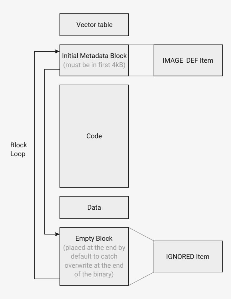
The diagram illustrates the structure of a binary image, showing a sequence of blocks and a loop mechanism. At the top is a 'Vector table' box. Below it is the 'Initial Metadata Block (must be in first 4kB)', which is linked to an 'IMAGE_DEF Item'. This is followed by a large 'Code' block, then a 'Data' block. At the bottom is an 'Empty Block (placed at the end by default to catch overwrite at the end of the binary)', which is linked to an 'IGNORED Item'. A 'Block Loop' is indicated by a vertical line on the left with arrows pointing to the 'Initial Metadata Block' and the 'Empty Block', showing a loop from the end back to the beginning.
The first block must be within the first 4 kB of the image, and is an IMAGE_DEF block describing the image. This block is linking to an empty block at the end of the image, that is included in the block loop to help detect partially written binaries. If the end of the image is missing or overwritten, then the block loop not be properly closed and will be considered invalid.
picotool can be used to sign a binary, in which case it modifies the image as follows:
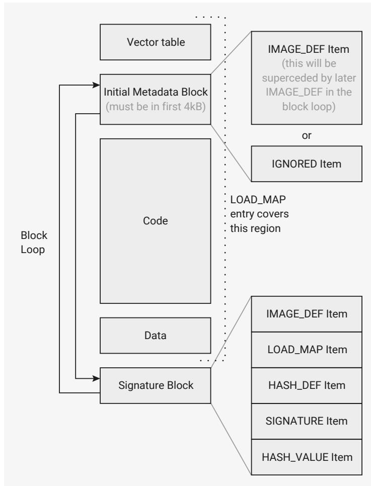
The diagram illustrates the structure of a block loop in memory. The block loop consists of the following components in sequence:
- Vector table
- Initial Metadata Block (must be in first 4kB)
- Code
- Data
- Signature Block
Annotations and links:
- The Initial Metadata Block is linked to an IMAGE_DEF Item (this will be superseded by later IMAGE_DEF in the block loop) or an IGNORED Item .
- The Signature Block is linked to a stack of items: IMAGE_DEF Item , LOAD_MAP Item , HASH_DEF Item , SIGNATURE Item , and HASH_VALUE Item .
- A LOAD_MAP entry covers the region of the Code and Data blocks.
Note that the marker block at the end of the image has been replaced with a new IMAGE_DEF block including the first block's information along with additional new information. The new information includes the signature (or hash value if hashing only), along with a LOAD_MAP entry indicating the regions of the image that are signed or hashed.
At runtime, the bootrom will pick the last valid IMAGE_DEF in the block loop as the one to boot.
Signing requires a SHA-256 hash of the data specified in the LOAD_MAP , along with the words of the block specified by the HASH_VALUE Item (which must include the first word of the SIGNATURE Item). This hash is then signed with an ECDSA secp256k1 private key, to produce the 64 byte signature stored in the SIGNATURE Item.
For secure boot, it is recommended to use packaged SRAM binaries instead of flash binaries, as the signature check is only performed during boot, so a malicious actor with physical access could replace the data on the external flash after the signature check to run unsigned code.
To sign and/or hash a binary in the SDK, you can add the following functions to your CMakeLists.txt file:
pico_sign_binary(target_name /path/to/keyfile.pem)
pico_hash_binary(target_name)
This will invoke the picotool seal command to sign and/or hash your binary when you call pico_add_extra_outputs . You can manually invoke picotool seal to sign and/or hash a binary using:
$ picotool seal --sign --hash unsigned.elf signed.elf private.pem
5.10.3. Packaged binaries
A packaged binary is an SRAM/XIP RAM-only binary that has been post-processed for storage in flash. To create a packaged SRAM binary, you can take a binary compiled to run in SRAM (
no_flash
binary in the SDK) and add a relative
LOAD_MAP
Item into the
IMAGE_DEF
block, with the runtime address(es) in SRAM. The subsequent binary can then be run normally from RAM, or stored in flash to be loaded into RAM by the bootrom. This
LOAD_MAP
item will be added to all binaries when using
picotool seal
.
To package binaries in the SDK, add the following to your CMakeLists.txt file. This will target the UF2 file to the start of flash when dragged and dropped, and will invoke
picotool seal
to add an appropriate
LOAD_MAP
.
pico_package_uf2_output(target_name 0x10000000)
Alternatively, you can use an absolute
LOAD_MAP
, with the
storage_address
in flash and the
runtime_address
in SRAM. However, these binaries can only run after storing in flash and can't be booted directly in SRAM for debugging.
For example, if you have a binary compiled to run at
0x20000000
of length
0x8000
, and a metadata block at the end of the binary containing the
LOAD_MAP
as the second Item (after the
IMAGE_DEF
, which means the
LOAD_MAP
is 8 bytes into the block), then the relative
LOAD_MAP
would be:
| Word | Bytes | Value |
|---|---|---|
| 0 | 1 | 0x06 (
size_flag
== 0,
item_type
==
PICOBIN_BLOCK_ITEM_LOAD_MAP
) |
| 2 | 0x04 (Block size in words) | |
| 1 | 0x01 ( absolute == 0, num_entries == 1) | |
| 1-3 | Load Map Entry 0 | |
| 4 | -0x8008 = 0xFFFF7FF8 ( storage_start_address_rel ) | |
| 4 | 0x20000000 ( runtime_start_address ) | |
| 4 | 0x8000 (size in bytes) | |
The absolute
LOAD_MAP
would be:
| Word | Bytes | Value |
|---|---|---|
| 0 | 1 | 0x06 (
size_flag
== 0,
item_type
==
PICOBIN_BLOCK_ITEM_LOAD_MAP
) |
| 2 | 0x04 (Block size in words) | |
| 1 | 0x81 ( absolute == 1, num_entries == 1) | |
| 1-3 | Load Map Entry 0 | |
| 4 | 0x10000000 ( storage_start_address ) | |
| 4 | 0x20000000 ( runtime_start_address ) | |
| 4 | 0x20008000 ( runtime_end_address ) | |
5.10.4. A/B booting
This is a common boot scenario, to be able to update the software without overwriting it. A simple partition layout would be:
Partition 0
  Accepts UF2 Families: rp2350-arm-s, rp2350-riscv
Partition 1
  Accepts UF2 Families: rp2350-arm-s, rp2350-riscv
  Link Type: "A"
  Link Value: 0
This is a partition table with 2 partitions, where partition 0 is the A partition of partition 1 (which is thus the B partition).
i NOTE
To avoid confusion, it is a recommended best practice to have the same permissions for both partitions, and for both partitions to accept the same UF2 families. The bootrom will only look at the UF2 families from the A partition when deciding if a given A/B pair accepts a particular family, and will not allow download to partition A even if it is writable if partition B isn't.
When dragging a UF2 to the device, it will target whichever partition is not currently booting. The bootrom will then perform a FLASH_UPDATE boot into the new binary (see Section 5.1.16 )
i NOTE
When starting with blank A/B partitions, the first download actually goes into partition B.
To create the partition table above with
picotool partition create
, the following json could be used:
{
  "version": [1, 0],
  "unpartitioned": {
    "families": ["absolute"],
    "permissions": {
      "secure": "rw",
      "nonsecure": "rw",
      "bootloader": "rw"
    }
  },
  "partitions": [
    {
      "name": "Example A",
      "id": 0,
      "size": "2044K",
      "families": ["rp2350-arm-s", "rp2350-riscv"],
      "permissions": {
        "secure": "rw",
        "nonsecure": "rw",
        "bootloader": "rw"
      }
    },
    {
      "name": "Example B",
      "id": 1,
      "size": "2044K",
      "families": ["rp2350-arm-s", "rp2350-riscv"],
      "permissions": {
        "secure": "rw",
        "nonsecure": "rw",
        "bootloader": "rw"
      }
    },
    {
      "link": ["a", 0]
    }
  ]
}
    }
  ]
}
This can then be installed onto the device using
picotool load
, or UF2 drag and drop if you output the partition table as a UF2 file.
5.10.5. A/B booting with owned partitions
The concept of owned partitions applies when:
- • you require separate data partitions (which generally won't contain a block loop ), but
- • you would like these to be associated with a specific boot partition in an A/B pair
An example partition table for this scenario would be:
Partition 0
  Accepts Families: rp2350-arm-s, rp2350-riscv
Partition 1
  Accepts Families: rp2350-arm-s, rp2350-riscv
  Link Type: "A"
  Link Value: 0
Partition 2
  Accepts Families: data
  Link Type: "Owner"
  Link Value: 0
  ignored_during_arm_boot: true
  ignored_during_riscv_boot: true
Partition 3
  Accepts Families: data
  Link Type: "A"
  Link Value: 2
  ignored_during_arm_boot: true
  ignored_during_riscv_boot: true
This is a partition table with 4 partitions. As before, partition 0 is the A partition of partition 1 (which is thus a B partition). Additionally, partition 2 is the A partition of partition 3 (which is thus a B partition). Finally, partition 0 is the "owner" partition of partition 2.
As a result partitions 2 and 3 "belong to" partitions 0 and 1.
When downloading a UF2 into an owned partition, the bootloader will select which partition out of 2/3 it goes to target based on which partition out of 0/1 is currently booting. For example, if partition 1 is currently booting (due to having a higher version than partition 0), then any UF2 downloads with the data family ID will target partition 3.
 TIP
TIP
There is a flag in each partition that you can use to swap the "affinity", for example, to have the data family ID target partition 2 instead of partition 3 in the scenario above.
NOTEOnly the
get_uf2_target_partition()
bootrom function considers owner partitions. The
pick_ab_partition()
function always pick solely based on the A/B partition it is passed, in other words if passed partition 2, it would not look at partitions 0 and 1.
To create this partition table using
picotool partition create
, the following JSON could be used:
{
  "version": [1, 0],
  "unpartitioned": {
    "families": ["absolute"],
    "permissions": {
      "secure": "rw",
      "nonsecure": "rw",
      "bootloader": "rw"
    }
  },
  "partitions": [
    {
      "name": "Example A",
      "id": 0,
      "size": 128k,
      "families": ["rp2350-arm-s", "rp2350-riscv"],
      "permissions": {
        "secure": "rw",
        "nonsecure": "rw",
        "bootloader": "rw"
      }
    },
    {
      "name": "Example B",
      "id": 1,
      "size": 128k,
      "families": ["rp2350-arm-s", "rp2350-riscv"],
      "permissions": {
        "secure": "rw",
        "nonsecure": "rw",
        "bootloader": "rw"
      }
    },
    {
      "link": ["a", 0]
    },
    {
      "name": "Example a",
      "id": 2,
      "size": 20k,
      "families": ["data"],
      "permissions": {
        "secure": "rw",
        "nonsecure": "rw",
        "bootloader": "rw"
      }
    },
    {
      "link": ["owner", 0],
      "ignored_during_arm_boot": true,
      "ignored_during_riscv_boot": true
    },
    {
      "name": "Example b",
      "id": 3,
      "size": 20k,
      "families": ["data"],
    }
  ]
}
    "permissions": {
        "secure": "rw",
        "nonsecure": "rw",
        "bootloader": "rw"
    },
    "link": ["a", 2],
    "ignored_during_arm_boot": true,
    "ignored_during_riscv_boot": true
}
]
}
This can then be installed onto the device using
picotool load
, or UF2 drag and drop if you output the partition table as a UF2 file.
5.10.6. Custom bootloader
In this scenario, a bootloader is run before booting into an image. This could perform additional validation, or set up peripherals for use by the image. For this to work, the block loop must contain both an
IMAGE_DEF
for the bootloader and a
PARTITION_TABLE
to define the flash layout.
In this example, we want to have A / B versions of the bootloader, so we use both slot 0 and slot 1. See Section 5.1.15 for more details of this, as you may well need to increase the size of slot 0 in order to fit the bootloader.
⚠ WARNING
Making a slot size change is not reversible, so feel free to leave out slot 1 if you try this in practice.
An example flash layout might resemble the following:
Slot 0 (0x00000000-0x00008000)
  Bootloader Image 0
  Partition Table 0
Slot 1 (0x00008000-0x00010000)
  Bootloader Image 1
  Partition Table 1
Partition 0 (0x00010000-0x00020000)
  Binary A
Partition 1 (0x00020000-0x00030000)
  Link Type: "A"
  Link Value: 0
  Binary B
The block loop with both
IMAGE_DEF
and
PARTITION_TABLE
might look like this (after signing in this case):
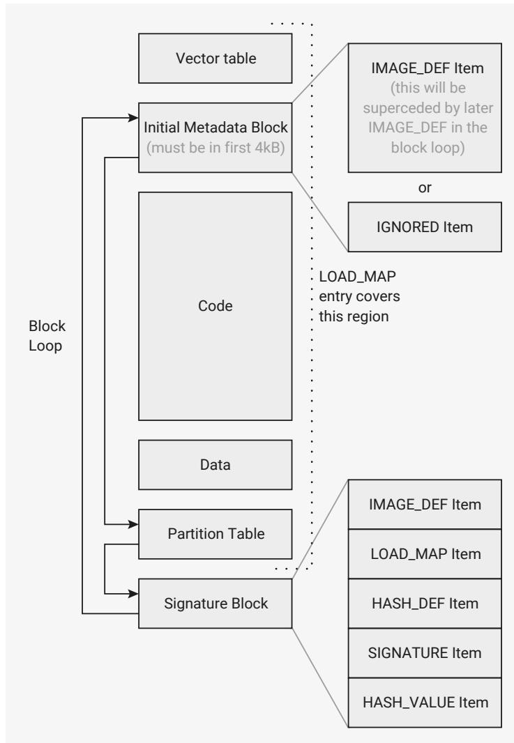
Note the 3 blocks in the block loop:
- 1. Original block in first 4 kB (contents doesn't matter, as it will be superseded by the later
IMAGE_DEF) - 2.
PARTITION_TABLEat end of binary - 3. Signed
IMAGE_DEF
i NOTE
It is possible to sign both the
PARTITION_TABLE
and the
IMAGE_DEF
separately, however for the fastest boot speed, the bootrom also allows you to use a "covering"
LOAD_MAP
in the
IMAGE_DEF
. As long as the
LOAD_MAP
defined area to be hashed/signed includes the entirety of the
PARTITION_TABLE
block, the "covering" signature is used to validate the
PARTITION_TABLE
too.
For the bootloader to find and launch a new image, it may wish to utilise various bootrom methods:
- •
get_partition_table_info()to get the full partition information. - • or
get_partition_table_info()withSINGLE_PARTITION, the chosen partition number, andPARTITION_LOCATION_AND_FLAGS, to get the address of a single partition
uint32_t partition_info[3];
get_partition_table_info(partition_info, 3, PT_INFO_PARTITION_LOCATION_AND_FLAGS
    | PT_INFO_SINGLE_PARTITION | (boot_partition << 24));
uint16_t first_sector_number = (partition_info[1]
    & PICOBIN_PARTITION_LOCATION_FIRST_SECTOR_BITS)
    >> PICOBIN_PARTITION_LOCATION_FIRST_SECTOR_LSB;
uint16_t last_sector_number = (partition_info[1]
    & PICOBIN_PARTITION_LOCATION_LAST_SECTOR_BITS)
    >> PICOBIN_PARTITION_LOCATION_LAST_SECTOR_LSB;
uint32_t data_start_addr = first_sector_number * 0x1000;
uint32_t data_end_addr = (last_sector_number + 1) * 0x1000;
uint32_t data_size = data_end_addr - data_start_addr;- •
get_sys_info()withBOOT_INFO, to get theflash_update_boot_window_baseif any:
uint32_t sys_info[5];
get_sys_info(sys_info, 5*4, SYS_INFO_BOOT_INFO);
uint32_t flash_update_boot_window_base = sys_info[3];
- •
pick_ab_partition()to pick the boot partition between A/B partitions if desired:
uint8_t boot_partition = pick_ab_partition(workarea, 0xC00, 0,
flash_update_boot_window_base);- • or
get_b_partition()to find the other partition directly. - •
chain_image()withdata_start_addranddata_size, to boot a chosen image:
// note a negative 3rd parameter indicates to chain_image that the image is being chained as
// part of a "flash update" boot, so TBYB and/or version downgrade may be in play
chain_image( workarea,
    0xC00,
    (XIP_BASE + data_start_addr) * (info.boot_type == BOOT_TYPE_FLASH_UPDATE ? -1 :
1),
    data_size
);
NOTE
The
workarea
used must not overlap the image being chained into, so beware SRAM or packaged binaries. If the binary overlaps the
workarea
, the results are undefined, but hardly likely to be good.
5.10.7. OTP bootloader
This is similar to the custom bootloader scenario, but it will be stored in the OTP and will run in SRAM.
One possible use case could place decryption code into OTP which decrypts an executable image from a flash partition into RAM.
The entire bootloader will need to fit in the OTP rows from
0x0C0
to
0xF48
to avoid interfering with other reserved OTP functionality, giving a maximum size of 7440 bytes (2 bytes per ECC row). If some boot keys and OTP keys are unused, this region can extend slightly on either end.
The OTP bootloader itself should be stored in ECC format, starting from the row set in OTPBOOT_SRC with size set in OTPBOOT_LEN . When booting, it will be loaded into the address specified in OTPBOOT_DST0 and OTPBOOT_DST1 , which must be in the main SRAM. The bootloader must fulfil the same criteria as a standard image: it must include an IMAGE_DEF , which must be signed if secure boot is enabled.
Once the OTP bootloader has been written to OTP, and the OTPBOOT_SRC , OTPBOOT_LEN , OTPBOOT_DST0 and OTPBOOT_DST1 set, OTP booting can be enabled by setting BOOT_FLAGS0.ENABLE_OTP_BOOT . If the OTP image fails the bootrom's launch checks, then, by default, boot continues along the normal flash boot path. You can prevent this by setting BOOT_FLAGS0.DISABLE_FLASH_BOOT .
⚠ WARNING
Take extreme care when writing an OTP bootloader. Once the ECC rows are written, they cannot be modified.
5.10.8. Rollback versions and bootloaders
⚠ WARNING
Ignoring the advice in this section could render your device unable to boot.
For bootloaders that need to chain into executable images with rollback versions on a secured RP2350, you must use separate OTP rows for:
- • The bootloader rollback version
- • The chained executable image's rollback version
Otherwise, bumping the version of the chained executable image renders the OTP bootloader and your device unable to boot.
You must also make sure that both the bootloader and the executable image have non-zero rollback versions, as the OTP flags relating to requiring rollback versions are global. Failure to do so will render your device unable to boot.
We recommend using the DEFAULT_BOOT_VERSION0 and DEFAULT_BOOT_VERSION1 rows for the binary's rollback version, and selecting some other unused rows in the OTP for the bootloader's rollback version.